

Page 1

Supplied By www.heating spares.co Tel. 0161 620 6677
AquaFlow
Single coil water cyliner
Installation
& Servicing
Instructions
THESE INSTRUCTIONS
TO BE RETAINED
BY USER
Vokèra is a licensed member of the Benchmark scheme
which aims to improve the standards of installation and
commissioning of domestic hot water systems in the UK.
Page 2
Supplied By www.heating spares.co Tel. 0161 620 6677
PLEASE LEAVE THIS MANUAL WITH THE UNIT AFTER INSTALLATION
00
Aquaflow
Single coil water cylinder
INSTALLATION MANUAL
This manual gives detailed advice for installation and should be read carefully
prior to fitting any unvented unit. This Vokera Aquaflow cylinder must be installed
by a competent person and be installed in compliance with the Vokera Aquaflow
Installation and Maintenance Instructions, all current legislation, codes of practice
and regulations governing the installation of unvented hot water cylinders in force
at the date of installation.
Components supplied with the unit for site fitting
(See also page 2 for component list)
* Multibloc valve, includes pressure reducing valve, line strainer, balanced cold water take off, (for
shower or bidet only) check and expansion valve.
* Tundish.
* 1/2"F x 15 x 15 tee piece.
* Flexible hose.
* 3/4" x 22 mm Elbow / Drain Cock
* Commissioning valve, 1/2" BSP male.
• Motorized valve.
• Expansion vessel
Components factory fitted
* Immersion heater(s).
* Thermostats / thermal cut-out.
* Temperature and press
ure relief valve.
Manual Handling Operations Regulations 1992 defines manual
handling as: "any transporting or supporting of a load (including the
lifting, putting down, pushing, pulling, carrying or moving thereof) by
hand or bodily force" The Regulations set no specific requirements
such as weight limits. However common sense still has to be used
based on an ergonomic approach for each individual
DIMENSION AND WEIGHTS TABLE 1
PRODUCT REF. 120 150 200 250
HEIGHT 720 900 1150 1600
DIAMETER 580 580 580 580
WEIGHT EMPTY 34 40 48 64
MAX WEIGHT FULL 132 163 215 303
Health and Safety
-
Installation details
The Vokera unvented unit is designed for use with supply pressure up to 16 bar. For pressures
over 16 bar an additional pressure reducing valve must be fitted in the supply pipe to the unit. Wall
mounting brackets are available for Vokera Aquaflow unvented units 120-200 litres capacity.
-1-
Page 3
Supplied By www.heating spares.co Tel. 0161 620 6677
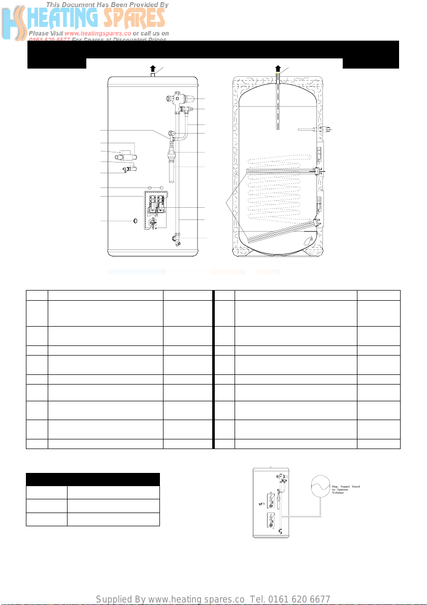
General Layout Fig: 1
INDIRECT
2
RESET
1
1
2
3
4
1
4
2
RESET
5
1
1
1
1
9
3
4
16
1
8
1
2
4
15
1
222
1
33113
RESET
RESET
4
4
2
2
1
2
10
5
6
17
7
7a
8
13
KEY Part No KEY Part No
1 Flow BSPF * 10 Flexible Hose 202108
2 Return BSPF * 11 Secondary Return ½”BSPF
3 Pressure Reducing Valve
510503 12 Commisioning Valve / Fitting
Includes Item 4
4 Check and Expansion Valve 510505 13 Elbow / Drain Cock 250445
5 Temperature and Pressure
550803 14 Cable Entry
Relief Valve
6 Tundish 219002 15 Electrical Box
7 Immersion Heater 71255 16 Tee Piece 250006
7A Thermostat Immersion Heater
Thermostat Cylinder
80400
80511
8 Cold Feed Tube
(Not Supplied See Table 2)
9 Hot Water Outlet 22mm
Fit ½"Fx½"Mx15mm Tee piece
supplied)
(½" MI Drain Cock)
17 Discharge Pipe (Not supplied)
18 Motorised Valve Not Factory Fitted)
9
(Not
250440
92000
Series Length of tube (ø22) mm
120 480 mm
150 585 mm
200 760 mm
-2-
TABLE 2
Page 4

Supplied By www.heating spares.co Tel. 0161 620 6677
COLD WATER SUPPLY
1. To obtain the best performance from your Aquaflow unvented system it is advisable to feed
the unit with an uninterrupted supply.
2. Locate the water heater in a suitable posit
supply, discharge fittings and pipework. Also take into account access to the immersion
heaters and the commissioning valve.
3. Fit the combined male elbow / drain cock to cold
compression fitting is vertical.
4. Fit the commission
5. Fit the female outlet of the tee piece to the temperature and pressure relief valve (5) with
horizontal connection facing right at approx. 45°.
6. Fit the tundish (6) to the tee piece using a short length of 15 mm copper tube.
7. Fit the length of copper tube 22mm specified
8. Fit the pressure reducing valve (3) to the top of the copper tube (see
black knob is facing right.
9. Connect
of the tee piece (see 5 above). Discard compression nut & ring.
10. If
type only, ascending spray
cap from the pressure reducing valve (3) and connect to the shower or bidet cold supply.
(Major shower manufacturers advise fitting a mini expansion vessel in the balanced cold supply
pipework to accomodate thermal expansion and prevent tightening of shower controls)
the balanced cold connection to feed bath taps can reduce the flow available to the
unvented cylinder.
11. Before connecting the cold supply, flush the cold supply pipework of all flux and debris.
12. Connect the cold supply to the pressure reduction valve (Multibloc) (3).
the flexible hose to the 1/2" outlet of the expan
a balanced mains pressure cold water supply is required to a shower or bidet (over rim
ing valve (12) to the commissioning fitting .
type requires type AA,AB or AD air gap), remove the blanking
ion to facilitate the installation of
supply point (13), so that the
in Table 2 to the cold feed elbow (see 3 above).
sion valve (4) and the horizontal outlet
the cold water
7 above), so
the
that the
Using
Hot water supply
13. Connect the hot water supply pipe to the outlet (9). Ensure connection is water tight.
Secondary return
14. A secondary return facility is provided on all units. Fit a ½” F x ½” M x 15mm tee piece
between the commissioning valve (12) and the commissioning fitting. See also figure 4 on
page 16.
Discharge pipe
15. Connect the discharge pipe from the tundish (6)This must have a continuous fall and be
fitted in accordance with The Building Regulations (see pages 5 and 12).
Primary flow & return and motorised valve
16. The boiler primary flow and return connections should be made to the unit. The motorised
valve must be fitted into the primary flow. The primary flow and return fittings are 3/4" BSP
female.
17. For electrical connection of the motorised valve and immersion heater, please read Electrical
Installation Instructions. (Pages 7 – 11)
-3-
Page 5
Supplied By www.heating spares.co Tel. 0161 620 6677
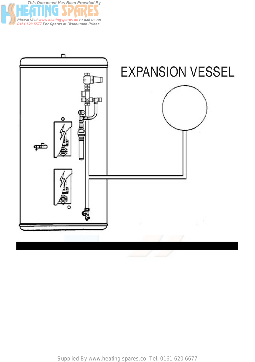
Expansion Vessel
18. Connect the expansion vessel (supplied) to the cylinder as shown in the diagram below. The
vessel should be charged/pressurised to the same pressure as the PRV (Pressure Reducing
Valve).
COMMISSIONING
Filling up
1. Close all hot water taps.
2. Open the commissioning valve (12).
3. Open the cold water supply valve.
4. When water flows from the commissioning valve (12), close the va
5. Allow system to stabilize for five mi
6. Open each hot water tap in turn to expel air from the system pipe work.
7. Check for
8. Manually operate Temperature and Pressure Relief Valve (5) to ensure free water flow through
discharge pipe.(Turn knob to left.)
leaks.
nutes.
-4-
lve.
Page 6
Supplied By www.heating spares.co Tel. 0161 620 6677
Draining
Switch off the electrical power off (Important to avoid damage to element). Isolate boiler from
Aquaflow unit. Turn off the cold water supply valve. Open hot water tap. Open drain (13). The unit
will drain.
SAFETY AND MAINTAINANCE
Safety Cut-out
1. The safety cut-out operates if:
a. Wiring is incorrect.
b. The immersion heater thermostat or cylinder thermostat fails.
c. Thermostat is set too high.
2. Remember
electrical supply to the unit prior to removal of the electrical box lid.
3. Reduce thermostat setting and press the reset button.
the lid to the electrical box is replaced correctly and the retaining screw is fitted.
4. If still out of operation,
before resetting the safety cut-out or altering the thermostat setting, iso
After adjustments are completed,
contact installer.
late
ensure
Cold or tepid water discharge from tundish
1. Turn off the electrical supply to the immersion heaters.
2. Turn off cold water supply valve.
3. Open a hot tap.
4. Drain water f
5. Turn the knob on the Temperature and P
position until water flow stops from the commissioning va
6. Close commissioning
7. Close all hot taps.
8. Open cold water supply valve.
9. Turn on electrical supply to the immersion heaters.
rom commissioning valve (12) until water flow stops.
ressure Relief Valve (5) to the left and hold in this
lve.
valve.
Hot water discharge from tundish
This indicates a malfunction of a thermal cut-out, operating thermostat or the combined temperature
and pressure relief valve. Turn off the electrical supply to the immersion heater and also isolate an
indirect unit from the boiler. Contact the installer or competent engineer.
INSTALLATION AND SERVICING INSTRUCTIONS
Cold water inlet control (Multibloc) See Page 2 Items 3 - 4
This combination consists of a pressure reducing valve with integral strainer, check valve and
expansion valve with stainless steel seat. The pressure settings are set and locked in the factory
and are shown on the top of each valve. For optimum performance the following installation
instructions should be complied with.
-5-
Page 7

Supplied By www.heating spares.co Tel. 0161 620 6677
Installation
1. Cold water supply to be 22 mm nominal size.
2. Flush supply pipework before connection to remove all flux and debris prior to fitting the inlet
controls. Failure to do this may result in irreparable damage to the controls and will invalidate
the warranty.
3. The "MULTIBLOC" can be fitted in any orientation to suit the installation as long as it is fitted in
the correct flow direction. Check the flow arrows on the side of the body.
4. The expansion valve should be e
deposited
flow arrows.
5. The black plast
monitoring to be carried out, should the system develop a fault. It is recommended that these be
accessible (the pressure reducing valve has two - only one need be accessible).
6. Expansion relief drain p
tundish and the pipework must have a continuous fall.
7. The pressure reducing valve has two outlets, the
supply, to a shower or a bidet (over rim type only, ascending spray type requires type
AA,AB or AD air gap)
the balanced cold supply pipework to accomodate thermal expansion and prevent tightening of
shower controls)
flow available to the unvented cylinder. The balanced cold supply is blanked off.
NOTE: If the unit has been commissioned and is to be unused for more than 8 weeks it is
advisable to turn off the cold supply and draw off approximately 5 litre of water through a hot
tap. NB The cold supply must be opened prior to use.
The Benchmark Log Book enclosed with the cylinder should be completed after
commissioning the syste
on the seat and cause fouling of the seat when the valve operates. Check direction of
ic plugs in the body are pressure gauge connections to enab
ipework must be connected to a safe visible discharge point via
(Major shower manufacturers advise fitting a mini expansion vessel i n
Using the balanced cold connection to feed bath taps can reduce the
ither horizontal or upright - if fitted inverted, debris may be
second one is for a balanced
m and handed to the cust
omer for future reference.
le pressure
cold water
a
MAINTENANCE
Under normal circumstances the "MULTIBLOC" combination control valve should not require any
maintenance. However, annual inspection and / or cleaning of the integral line strainer, pressure
reducing valve, cartridge, expansion relief valve cartridge and seating may be necessary depending
on local water conditions.
Pressure reducing valve
1. Isolate cold water supply.
2. Unscrew the retaining nut of the valve.
The complete operating mechanism,
including the
strainer can be removed.
3. Clean the filter mesh and the cartridge
under running water.
4. Replace cartridge ensuring that strainer
correctly located
-6-
and reassemble the unit.
is
Page 8

Supplied By www.heating spares.co Tel. 0161 620 6677
Pressure Reducing Valve cartridge and
strainer Part No. 510 501 2.1 Bar.
Expansion relief cartridge
1. Isolate cold water supply.
2. Unscrew blue expansion relief
headwork from valve body.
Pressure reducing valve
Cartridge and strainer
Part No. 510 501
Spare Parts
Expansion valve
(Cartridge)
Part No.
8.0 Bar 214009
6.0 Bar 214005
4.0 Bar 214046
Expansion valve
Part No. 510 505
8.0Bar
n valve seat face and seating - do not
3. Clea
scratch or damag
t in reverse order. Do not overtighten.
4. Refi
Expansion valve cartridge and seat Part No.
214009 8.0 Bar. Complete Expansion Valve
Part No. 510 505 8.0 Bar.
e either seal face or seating.
Tundish
Install the Tundish in a vertical position within a maximum of 500 mm from the Temperature and
Pressure Relief Valve drain connection. Ensure the expansion relief pipework discharges through
the tundish. Tundish pipework must be 22 mm with a minimum vertical length of 300 mm below
tundish. Maximum permitted length of 22 mm pipework is 9 m. Each bend or elbow is equivalent to
0.8 m of pipework.
All pipework must have continous fall and discharge in a safe, visible position. If any doubt, refer to
Building Regulation G3.
ELECTRICAL INSTALLATION
Immersion heaters
All units are fitted with one immersion heater which is located behind the electrical box.
Indirect Units
Motorised valve
To comply with regulations governing the installation of indirect unvented cylinders, a motorised
valve must be fitted in the primary flow. Your Aquaflow unit has been supplied with a two port
motorised valve, whi
motorised valve will also control the temperature of the domestic stored water via the cylinder
thermostat, which is located in the electrical box. The unit should be installed on an "S" or "Y" plan
ch will act as a positive energy cut-out should the safety cut-out operate. The
-7-
Page 9

Supplied By www.heating spares.co Tel. 0161 620 6677
system. Please follow the instructions carefully. All electrical connections must conform to
current IEE wiring regulations. The working thermostat which controls the temperature of the
domestic hot water (see fig. 2/2A) is adjustable between 45°C - 75°C. A safety cut out is also
incorporated within the thermostat and will operate at 85°C ± 3°C. Should the safety cut out be
brought into operation, the motorised valve will operate and close down the primary flow to the
cylinder. To reset the safety cut-out and the motorised valve the reset button must be pressed in
(see fig. 2/2A).If using a 6-wire 28mm or 1” BSP V4043H on either circuit the white wire is not
needed and must be made electrically safe.
Vokera can not be responsible if alternative wiring plans are used.
Important: Before resetting the
safety cut-out or altering the
thermostat setting isolate
electrical supply to the unit before removal of the lid.
’S’ Plan systems
Refer to the wiring diagrams contained within the boiler installation instructions for the wirng of ’S’Plan systems. Connect the cylinder thermostat as shown in the diagram below
-8-
Page 10

Supplied By www.heating spares.co Tel. 0161 620 6677
S Plan System Schematic
Y Plan Wiring Layout
Refer to the wiring diagrams contained within the boiler installation instructions for the wirng of ’Y’Plan systems. Connect the cylinder thermostat as shown in the diagram below
NOTE
A 10 way junction box must be used on the Y plan system.
.
-9-
Page 11

Supplied By www.heating spares.co Tel. 0161 620 6677
Y Plan System Schematic
AQUAFLOW FAULT FINDING GUIDE
FAULT POSSIBLE CAUSE REMEDY
No water flow from hot taps 1. Mains supply off. 1. Check and open stopcock.
-10-
Page 12

Supplied By www.heating spares.co Tel. 0161 620 6677
2. Strainer blocked.
3. Cold water inlet Pressure
Reducing Valve incorrectly
fitted.
Water from hot taps is cold. 1. Immersion heaters not
switched on.
2. Immersion heater thermal cutout has operated.
3. Programmer set to central
heating or not switched on.
4. Boiler not working.
5. Cylinder thermal cut-out has
operated.
6. Motorised valve not operating
correctly.
Intermittent water discharge. 1. Reduced expansion capacity.
2. Thermal control failure.
(Note Water will be hot).
Continuous water discharge. 1. Cold water inlet Pressure
Reducing Valve not
working.
2. Temperature and pressure
relief valve faulty.
3. Expansion relief valve not
working correctly.
NOTE: Disconnect electrical supply before removing any electrical equipment covers.
2. Turn off water supply. Remove
strainer and clean. (See Pressure
Reducing Valve page 6 Installation
Manual)
3. Check and refit as required.(see item
3 page 5 of installation manual)
1. Check and switch on.
2. Check and reset button. (See
thermostat diagram page
9 and safety cut-out on page 4 of
Installation manual).
3. Check and set to hot water.
4. Check boiler operation. If fault
suspected consult installer or boiler
manufacturer.
5. As at No. 2.
6. Check wiring and / or plumbing
connections to motorized valve. (See
pages 8 or 10 of the installation
manual).
1. Recharge expansion vessel to correct
charge (same as pressure reducing
valve).
2. Switch off power to immersion
heater(s) and boiler supply to the unit.
When discharge has stopped, check
thermal controls, replace if faulty.
Contact a competent person.
1. Check pressure from valve if greater
than 2.1 bar replace. (See page 6 of
installation manual)
2. As No. 2 of above.
3. Check and replace if faulty. (See
page 6 of installation manual).
-11-
Page 13

Supplied By www.heating spares.co Tel. 0161 620 6677
AQUAFLOW FAULT FINDING GUIDE
-12-
Page 14

Supplied By www.heating spares.co Tel. 0161 620 6677
-13-
Page 15

Supplied By www.heating spares.co Tel. 0161 620 6677
-14-
Page 16

Supplied By www.heating spares.co Tel. 0161 620 6677
Notes:
-15-
Page 17

Supplied By www.heating spares.co Tel. 0161 620 6677
ALTERNATIVE DISCHARGE
Downward discharges at low level, i.e. up to 100 mm above external surfaces su ch as car parks, hard st andings, grassed areas
etc. are acceptable provid ing that where ch ildren may play or ot herwise come into contact with discharges, a wire cage or similar
guard is positioned to prevent cont act, whilst maintaining visibility.
Discharge at high level, i.e. into a metal hopper and meta l down pipe
FIGURE 3
with the end of
not) or onto a roof capab le of withstanding high temperatur e
that would collect such discharges (tundish visible).
Where a single pipe serves a number of discharges, such as in
blocks of fl
6 systems so that any installation discharging can be traced
reasonably easily. The sing le common discharge pipe should be at
least one pipe size larger than the largest individual discharge pipe to
be connected. For further information contact your Building Control
Office or The British Board o f Agrément.
the discharge pipe clearly visible (tundish visible or
discharges of water and 3 m from any plastics guttering system
ats, the number
served should be limited to not more than
SECONDARY RETURN
FIGURE 4
1 Secondary Return use ½”Fx½”Mx15mm Tee (not supplied)
2 Commisioning Valve
3 Non Return Valve
4 Circulation Pump
5 Secondary Return Line
6 Balanced cold supply for showers or bidet only.
All replacement parts must be supplied by Vokera.
To obtain the address of a local stockist
Vokera Ltd. www.vokera.co.uk.
Catherine House
Boundary Way
Hernel Hempstead
Herts HP2 7RP E-mail: enquiries@vokera.co.uk
Phone: (0870) 333 0220
Fax: (01442) 281 460 A Riello Group Company.
-16-
contact:
Page 18

Supplied By www.heating spares.co Tel. 0161 620 6677
Registered address:
Unit 7 Riverside Industrial Estate
enquiries@vokera.co.uk
www.vokera.co.uk
Vokèra Ltd
Borderlake House
London Colney
Herts AL2 1HG
www.vokera.ie
Sales, General Enquires
T 0844 391 099
F 0844 391 0998
Vokèra Ireland
West Court, Callan
Co Kilkenny
T 056 7755057
F 056 7755060
Vokèra Limited reserve the right to change
specification without prior notice
Consumers statutory rights are not affected.
A Riello Group Company.
Company Reg No: 1047779
 Loading...