


High-performance Universal Joint Shafts
including ATEX certification
Series: S, R, CH, E
Instruction manual (Translation) G853 en 07/2013, Version 1

J.M. Voith SE & Co. KG/VTA | Instruction Manual
High
Instruction manual (Translation)
Publisher
Document number
Date of issue
Copyright
If you have questions regarding the product, please contact us
specifying the serial number and parts list number:
J.M. Voith SE & Co. KG/VTA
Universal Joint Shafts
Alexanderstr. 2
89522 Heidenheim, Germany
Additional contact information:
Telephone +
Fax
E-Mail
Web
49 7321 37-8283
+49 7321 37-7106
UJShafts@Voith.com
www.voith.com
J. M. Voith SE & Co. KG/VTA
Universal Joint Shafts
Alexanderstr. 2
89522 Heidenheim, Germany
E-Mail: UJShafts@Voith.com
G853 en 07/2013 Version 1
July 16, 2013
© 2013, J. M. Voith SE & Co. KG/VTA
This documentation including all of its parts is protected by
copyright. Any use or change outside of the narrow boundaries of
copyright law is not permitted without the agreement of J.M.
Voith SE & Co. KG/VTA and is punishable by law.
This applies especially to copying, translations, microfilming, and
the saving and processing on electronic systems.
2
G853 en 07/2013, Version1
-performance universal joint shaft

J. M. Voith SE & Co. KG/VTA | Instruction Manual
High
Instruction manual (Translation)
Table of contents
Contents
1 About this instruction manual .....................................................................................7
1.1 Target groups ................................................................................................................ 7
1.2 Product observation ..................................................................................................... 7
1.3 Other applicable documents ....................................................................................... 8
1.4 Additional documents .................................................................................................. 9
1.5 Symbols and markings..................................
.............................................................10
1.6 Warning ........................................................................................................................11
1.6.1 Levels of danger ...........................................................................................................11
1.6.2 Safety symbols ..............................................................................................................12
2 Basic Safety Information ........................................................................................... 13
2.1 Product safety .............................................................................................................13
2.2 Proper use ...................................................................................................................13
2.3 Remaining risks ..........................................................................................................14
2.4 Safety information for the operator ..........................................................................15
2.5 Safety information for the personnel ........................................................................17
2.6 Personal protective equipment .................................................................................21
2.7 Spare parts ..................................................................................................................21
3 High-performance Universal Joint Shafts ..............
................................................. 22
3.1 Structure ......................................................................................................................22
3.2 Application ..................................................................................................................25
3.3 Series ...........................................................................................................................26
3.3.1 Type designations .........................................................................................................26
3.3.2 S Series ........................................................................................................................27
3.3.3 R Series ........................................................................................................................27
3.3.4 CH Series ......................................................................................................................28
3.3.5 E Series ........................................................................................................................28
4 Packaging, transport ................................................................................................. 29
4.1 Packaging ....................................................................................................................29
G853 en 07/2013, Version1
4.2 Unpacking the universal joint shaft and checking the delivery .............................29
4.3 Lifting, transporting, setting down the universal join
-performance universal joint shaft
t shaft ..................................30
3

Table of contents
High
Instruction m
J.M. Voith SE & Co. KG/VTA | Instruction Manual
5 Storage and preservation ......................................................................................... 33
5.1 Storing the universal joint shaft ................................................................................33
5.2 Preserving the universal joint shaft ..........................................................................34
6 Installation .................................................................................................................. 35
6.1 Additional regulations for flange bolted connections ............................................35
6.1.1 Requirements of connecting flange and bolted connections .........................................35
6.1.2 Checking bolted connections and tightened parts .......
.................................................41
6.2 Installing the universal joint shaft .............................................................................42
6.2.1 Removing preservation .................................................................................................44
6.2.2 Transport universal joint shaft to the installation location .............................................44
6.2.3 Cleaning the universal joint shaft and connecting flange .............................................45
6.2.4 Checking, aligning, and fastening connecting flange ...................................................45
6.2.5 Checking the differential angle of the front faces of the connecting flange (with Z
arrangement) ................................................................................................................46
6.2.6 Checking the differential angle of the front faces of the connecting flange (with
W arrangement) ............................................................................................................47
6.2.7 Bolting together the universal joint shaft and the connecting flange ............................47
6.2.8 Final work ......................................................................................................................48
6.3 Additional regulations for Hirth serration ................................................................49
6.4 Additional regulations for use in paper machines ..................................................50
7 Commissioning and operation ................................................................................. 51
7.1 Commissioning the universal joint shaft ...............
..................................................51
7.2 Operating the universal joint shaft ...........................................................................52
8 Eliminating errors ...................................................................................................... 53
9 Maintenance ............................................................................................................... 55
9.1 General notes about the maintenance and inspection of universal joint shafts .56
9.2 Intervals for maintenance and inspections ..............................................................57
9.3 Inspections ..................................................................................................................58
9.3.1 Checking axial clearance of the journal cross set ........................................................58
9.3.2 Checking deflection play of the center part...................................................................59
9.4 Lubrication ..................................................................................................................61
9.4.1 Lubricants .....................................................................................................................61
9.4.2 Lubricating the universal joint shaft .................
.............................................................61
9.5 Main overhaul ..............................................................................................................64
anual (Translation) G853 en 07/2013, Version1
-performance universal joint shaft
4

J.M. Voith SE & Co. KG/VTA | Instruction Manual
High
Instruction manual (Translation)
Table of contents
9.6 Life span of ATEX universal joint shafts ..................................................................64
10 Removal ...................................................................................................................... 65
11 Repair .......................................................................................................................... 67
12 Disposal ...................................................................................................................... 67
13 Declaration of incorporation ........................
............................................................. 68
14 Declaration of conformity ......................................................................................... 69
15 Index ............................................................................................................................ 70
G853 en 07/2013, Version1
-performance universal joint shaft
5

Table of contents
High
Instruction m
List of figures
Table index
J.M. Voith SE Co. KG/VTA| Instruction Manual
Fig. 3.1: Structure of the universal joint shaft (example of type
RT) ............................................................................ 22
Fig. 3.2: Nameplate of an ATEX-certified universal joint shaft 23
Fig. 3.3: Schematic structure of temperature monitoring ....... 24
Fig. 3.4: Z arrangement .......................................................... 25
Fig. 3.5: W arrangement ......................................................... 25
Fig. 4.1: Attaching the universal joint shaft ............................. 32
Fig. 6.1: Dimensions of the connecting flange and bolted
connections ............................................................... 36
Fig. 6.2: Dimensions of a stud screw ..........................
............ 41
Fig. 6.3: Universal joint shaft .................................................. 44
Fig. 6.4: Checking the difference in joint angle between the
faces of the connecting flanges ................................ 46
Fig. 6.5: Permissible differential angle (with Z arrangement) . 46
Fig. 6.6: Seals for Hirth serration ............................................ 49
Fig. 6.7: Checking radial offset and flange distance (with use in
paper machines) ....................................................... 50
Fig. 9.1: Checking axial clearance of the journal cross set on
two levels .................................................................. 58
Fig. 9.2: Checking deflection play of the center part .............. 59
Fig. 9.3: Reading off deflection dimension ............................. 60
Fig. 9.4: Lubrication points of the universal joint shaft ........... 62
Tab. 1.1: Target groups ............................................................. 7
Tab. 1.2: Other applicable documents ....................................... 9
Tab. 1.3: Symbols and markings ............................................. 10
Tab. 1.4: Meaning of the danger levels ................................... 11
Tab. 1.5: Meaning of the safety symbols .......................
.......... 12
Tab. 2.1: Personal protective equipment ................................. 21
Tab. 6.1: Dimensions of the connecting flange and bolted
connections (key) ....................................................... 37
Tab. 6.2: Dimensions of the connecting flange and bolted
connections ............................................................... 40
Tab. 6.3: Permissible differential angle (with Z arrangement) . 46
Tab. 6.4: Permissible differential angle (with W arrangement) 47
Tab. 6.5: Permissible radial offset and flange distance (for use
in paper machines) ................................................... 50
Tab. 8.1: Eliminating errors ...................................................... 54
Tab. 9.1: Intervals for maintenance work and inspections ...... 58
Tab. 9.2: Checking axial clearance of the journal cross set .... 59
Tab. 9.3: Permissible deflection ratio....................................... 60
Tab. 9.4: Permissible lubricant quantity for the re-lubrication of
standard center parts. ............................................... 64
anual (Translation) G853 en 07/2013, Version1
-performance universal joint shaft
6

J.M. Voith SE & Co. KG/VTA | Instruction Manual
High
Instruction manual (Translation)
Target group
Task
About this instruction manual
1 About this instruction manual
Before you use the universal joint shaft, you must read this
instruction manually carefully and understand it.
This instruction manual is part of the product and familiarizes you
with the basic work on the universal joint shaft – from installation to
disposal.
It contains information about the safe and proper use of the
universal joint shaft.
1.1 Target groups
Operator Keep this instruction manual accessible to personnel at all
times.
Make sure that employees read and heed the instruction
manual and the other applicable documents, especially the
basic safety instructions and warnings.
Specialized personnel, service
engineer
1.2 Product observation
Heed additional system-related details and regulations.
Read, heed, and follow this instruction manual and the other
applicable documents, especially the basic safety instructions
and warnings.
Tab. 1.1: Target groups
We are under legal obligation to observe our products, even after
ipment.
sh
Therefore, please inform us about anything that might be of
interest, e.g.:
− Change in operating data
− Experience gained with the universal joint shaft
− Recurring problems
− Damage to the universal joint shaft
− Problems with the instruction manual
G853 en 07/2013, Version1
-performance universal joint shaft
7

About this instruction manual
High
Instruction manual (Translation)
Document
Information
Source
1.3 Other applicable documents
Documents for all designs
J.M. Voith SE & Co. KG/VTA| Instruction Manual
System documentation • System-specific information
about the removal and
installation of the universal joint
shaft.
Dimensional drawing of the
universal joint shaft
• Dimensions of the connection
flange.
• Tightening torques of the
bolted connections of the
flange connections.
• Weight of the universal joint
shaft.
• Shortest and maximum
permissible length of the
universal joint shaft.
Delivery note • Weight of the universal joint
shaft
Repair instructions for the
respective designs and sizes
For the manufacturer's authorized
service personnel:
• Information about repair of the
universal joint shaft
Operator
J.M. Voith SE & Co. KG/VTA
J.M. Voith SE & Co. KG/VTA
J.M. Voith SE & Co. KG/VTA
Balancing instruction For the manufacturer's authorized
service personnel:
• Information about the
balancing of the universal joint
shaft
Documents for special designs
Mounting and dismounting
instructions for split flange yokes
For designs with split flange yokes:
• Information about installing and
removing the universal joint
shaft
Mounting and dismounting
instructions for tripod center parts
For designs withtripod center parts:
• Information about installing and
removing the universal joint
shaft
Mounting and dismounting
instructions for spring-mounted
center parts
For designs with spring-mounted
center part:
• Information about installing and
removing the universal joint
shaft
J.M. Voith SE & Co. KG/VTA
J.M. Voith SE & Co. KG/VTA
J.M. Voith SE & Co. KG/VTA
G853 en 07/2013, Version1
-performance universal joint shaft
8

J.M. Voith SE & Co. KG | Instruction Manual
High
Instruction manual (Translation)
About this instruction manual
Mounting and dismounting
instructions for hydraulicallymovable center parts
Mounting and dismounting
instructions for deflection brakes
Mounting and dismounting
instructions for shaft angle
limiters
Mounting and dismounting
instructions for quick-release
couplings
For designs with hydraulic center
part:
• Information about installing and
removing the universal joint
shaft
For designs with deflection brake:
• Information about installing and
removing the universal joint
shaft
For designs with shaft angle
limitation:
• Information about installing and
removing the universal joint
shaft
For designs with quick-release
coupling:
• Information about installing and
removing the universal joint
shaft
Tab. 1.2: Other applicable documents
J.M. Voith SE & Co. KG/VTA
J.M. Voith SE & Co. KG/VTA
J.M. Voith SE & Co. KG/VTA
J.M. Voith SE & Co. KG/VTA
1.4 Additional documents
For additional information about the universal joint shafts, please
see the following documents:
• High-performance universal joint shafts catalogue
• General delivery conditions
• Hirth serrations
Order from: UJShafts@Voith.com
G853 en 07/2013, Version1
-performance universal joint shaft
9
About this instruction manual
High
Instruction manual (Translation)
Symbol
Meani
ng
1.5 Symbols and markings
Symbols and markings are used in this instruction manual in order
to allow you quick access to information.
J.M. Voith SE & Co. KG /VTA| Instruction Manual
Note about the effective use of the universal joint shaft
and this instruction manual
Note for ATEX certified universal joint shafts
1.
Action with several steps, whose sequence is relevant
2.
3.
Action with one step
–or–
Action with several steps, whose sequence is not
relevant
Prerequisite
•
List (first level)
−
List (second level)
Cross-reference to additional information
Tab. 1.3: Symbols and markings
G853 en 07/2013, Version1
-performance universal joint shaft
10
J.M. Voith SE & Co. KG/VTA | Instruction Manual
High
Instruction manual (Translation)
Level of danger
Likelihood of occurrence
Consequences if not heeded
DANGER
WARNING
CAUTION
1.6 Warning
For your safety, warnings are used in this instruction manual. The
warnings are next to the appropriate action instruction.
Depending on the likelihood of occurrence and consequences if
the instructions are not heeded, various danger levels are used.
The warnings are indicated with safety symbols, which depict the
type of danger visually.
1.6.1 Levels of danger
Imminent danger Death, severe bodily harm
Possible imminent danger Death, severe bodily harm
About this instruction manual
Possible imminent danger Slight bodily harm
Tab. 1.4: Meaning of the danger levels
G853 en 07/2013, Version1
-performance universal joint shaft
11
About this instruction manual
High
Instruction manual (Translation)
Safety symbols
Warning about
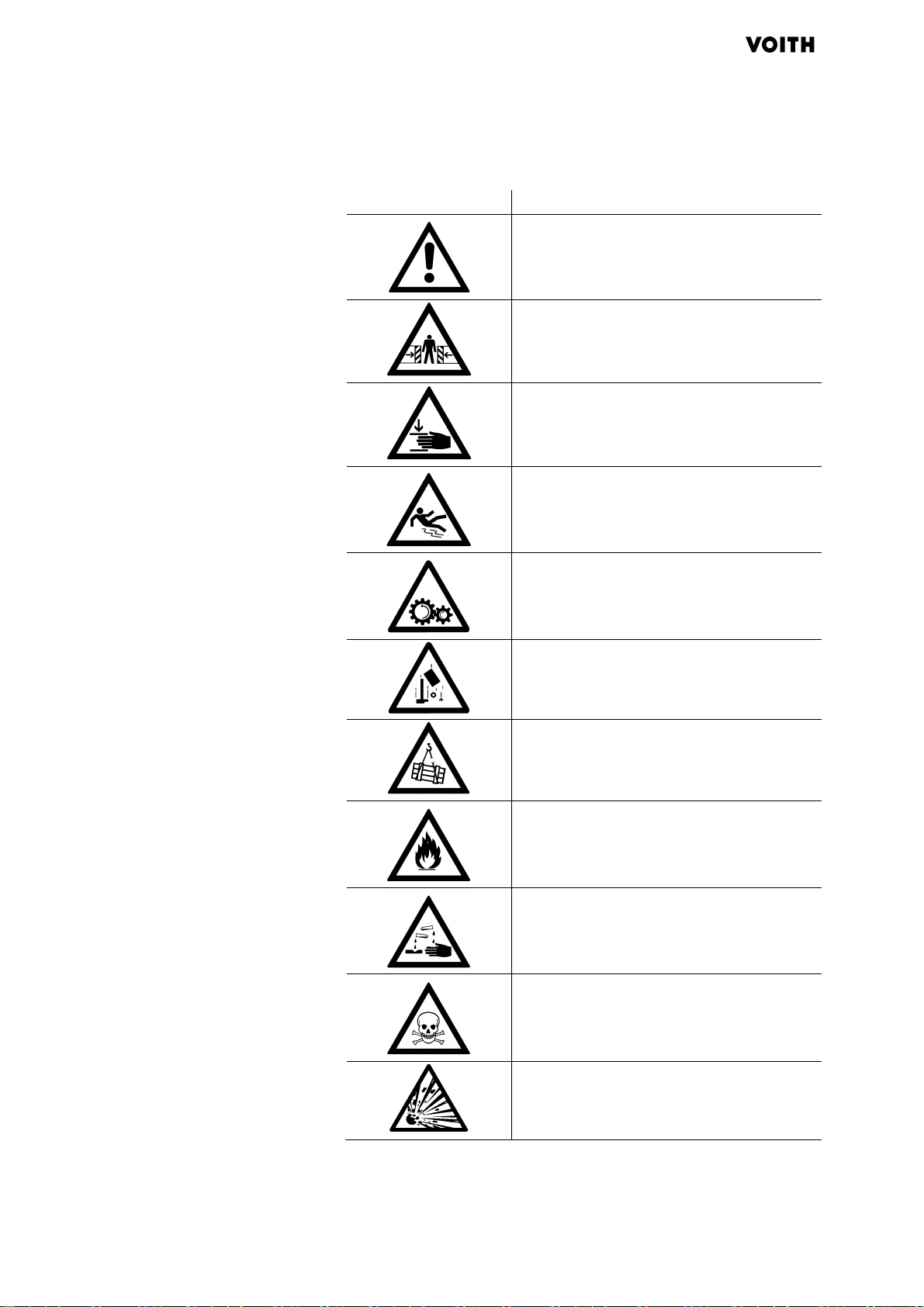
1.6.2 Safety symbols
J.M. Voith SE & Co. KG/VTA | Instruction Manual
General dangers
The type of danger is described in more
detail in the warning.
ushing
Cr
Hand injuries
Slipping
Rotating parts
Falling parts
Suspended loads
Flammable materials
Acidic materials
Poisonous materials
12
nger of explosion
Da
Tab. 1.5: Meaning of the safety symbols
G853 en 07/2013, Version1
-performance universal joint shaft

J.M. Voith SE & Co. KG/VTA | Instruction Manual
High
Instruction manual (Translation)
Foreseeable misuse
2 Basic Safety Information
Please heed the following safety information before engaging
in any activities.
2.1 Product safety
The universal joint shaft has been developed and built according to
he state of technology as well as the applicable safety regulations
t
at the time it was put on the market.
Nevertheless, its use can result in danger to life and limb of the
user or damage to the universal joint shaft itself and other property.
Only install the universal joint shaft if it is in proper condition
and only for the designated use, in a safety-conscious
manner that complies with the instruction manual.
Basic Safety Information
2.2 Proper use
Immediately correct (or have corrected) any defects that
adversely affect safety.
Universal joint shafts transmit torques between defined drive and
machine components. Therefore, the universal joint shaft is
intended for installation in the specific machine/system for which it
was selected.
Any other use, especially installation in other machines, is not
proper and forbidden.
Voith universal joint shafts are not approved for use in the food
industry.
In liquid media, universal joint shafts may only be used with written
permission of the manufacturer.
The universal joint shaft type we make and size can only be
regarded as recommendations.
Any improper use or activities on the universal joint shafts not
described in this instruction manual are impermissible misuse
outside of the legal liability limits of the manufacturer.
G853 en 07/2013, Version1
-performance universal joint shaft
Heed the following measures to avoid misuse:
nly operate the universal joint shaft within the specified
O
speed and torque range.
13

Basic Safety Information
High
Instruction manual (Translation)
J.M. Voith SE & Co. KG/VTA | Instruction Manual
Universal joint shafts are resiliently-flexible bodies that are
designed for bending vibrations and bending-critical speeds.
Therefore, for safety reasons, the maximum operating speed
must be significantly below the critical-bending speed 1st and
2nd order (see universal joint catalog G830).
For sufficient balance and security for the universal joint
shaft, it must be ensured that the operating speed does not
exceed the maximum permissible value depending on the
shaft angle (see universal joint catalog G830) and that the
driving and driven system parts are aligned with one another
(plan and concentric run-out see page 40)
Do not exceed permissible shaft angles of the universal joint
shaft.
Adhere to the lengths and temperatures specified for the
selection of the universal joint shaft.
For universal joint shafts with length compensation, make
sure that the maximum permissible movement path is not
exceeded.
2.3 Remaining risks
A local heating of the universal joint shaft, e.g. due to the
burning off of old color remnants is not permissible in order to
change the run-out properties.
Protect components coated with Rilsan against too-high
temperatures, chemical solvents, steam, and mechanical
damage.
Attaching parts to the universal joint shaft by welding or other
connection types is not permissible.
Adhere to the manufacturer's specifications with respect to
operation, maintenance, and repairs.
Have work on universal joint shafts done by the manufacturer
or by service technicians authorized by the manufacturer.
Do not make any unauthorized modifications or changes.
In areas subject to explosion (atmosphere), only use ATEXcertified universal joint shafts. Here, heed certification ( Chapter
3.1, page 22).
Before beginning construction and planning, the remaining risks of the
niversal joint shaft were analyzed and evaluated.
u
G853 en 07/2013, Version1
Remaining risks that could not be avoided during the entire life cycle
of the universal joint shafts are:
-performance universal joint shaft
14
J.M. Voith SE & Co. KG/VTA | Instruction Manual
High
Instruction manual (Translation)
Safety
-
conscious working
• Risk of death and injury due to
− Misuse
− Improper handling
− Improper transport
− Missing protection systems
− Defective or damaged mechanical parts
• Environmental hazard, e.g. due to
− Improper handling of preserving agents and lubricants
• Property damage to the universal joint shaft due to
− Improper handling
− Hazardous environmental influences, application
− Operating specifications not adhered to
− Unsuitable operating materials (e.g. bearing grease)
• Property damage to other assets due to improper handling
Basic Safety Information
conditions
• Performance or functional limitations due to
− Improper handling
− Improper maintenance or repair
− Subsequent damage due to overload
Avoid existing remaining risks with the practical imp
heeding of the following specifications:
• Basic safety instructions and warnings in this instruction manual
• Work instructions from the operator
• Technical data for the system ( system documentation)
2.4 Safety information for the operator
The operator must take appropriate safety precautions in
order to prevent the endangering of people and materials due
to rotating universal joint shafts and their parts.
For the operation of the universal joint shaft within a machine,
the EU machine directive must be heeded.
Ensure adherence and monitoring:
lementation and
G853 en 07/2013, Version1
-performance universal joint shaft
− Of proper use
− Of laws and regulations for accident prevention and
environmental protection
− Of safety regulations for the handling of hazardous
materials
− Of applicable standards and guidelines for the country of
operation
15

Basic Safety Information
High
Instruction manual (Translation)
Organizational measures
Selection and qualification of
J.M. Voith SE & Co. KG/VTA | Instruction Manual
Make protective equipment available ( Chapter 2.6, page
21).
For telescopic lengths without profile guard: provide guard in
the system.
Keep this instruction manual and all applicable documents
accessible to personnel at all times.
Specify responsibilities of the personnel clearly and monitor
adherence.
staff
All activities on the universal joint shaft may only
be performed by
authorized personnel.
Ensure that the staff members
− are at least 18 years old.
− have read and understood the "Basic safety information"
chapter.
− can apply and implement the contents of the "Basic safety
instructions" chapter.
− have the bodily and mental abilities to perform their
responsibilities, tasks, and activities on the universal joint
shaft.
− are trained according to their responsibilities, tasks, and
activities on the universal joint shaft.
− have understood and can practically implement the
technical documentation with respect to their
responsibilities, tasks, and activities on the universal joint
shaft.
− is familiar with and can apply the components of the
system and their function.
16
− is familiar according to his responsibilities with the
instructions for cleaning, preserving, lubricating, and using
hazardous materials and taking first aid measures in case
of accidents.
G853 en 07/2013, Version1
-performance universal joint shaft

J.M. Voith SE & Co. KG/VTA | Instruction Manual
High
Instruction manual (Translation)
Warranty
Safety
-
conscious wo
rking
The warranty is voided in case of any change to the universal
joint shaft without our written permission.
During the warranty, obtain the manufacturer's permission
before making repairs to the universal joint shaft.
Only use original parts or parts approved by the
manufacturer.
2.5 Safety information for the personnel
The consumption of alcohol, drugs, medications or other mind-
ltering substances is forbidden.
a
Protect universal joint shaft against unauthorized operation.
Adhere to applicable accident prevention regulations.
If necessary or required by regulations, wear personal
protective equipment ( Chapter 2.6, page 21).
Basic Safety Information
Keep unauthorized personnel out of the danger area of the
universal joint shaft.
Keep safety and notice signs on the universal joint shaft in
easily-legible condition, e.g. lubrication points.
Follow the supervisor or safety officer's safety and work
instructions.
Only linger in the workplaces provided in the danger area
( system documentation).
Do not make any constructional changes to the universal joint
haft.
s
Handle hazardous materials according to the safety data
sheets. Heed safety measures and wear personal protective
equipment.
G853 en 07/2013, Version1
-performance universal joint shaft
17

Basic Safety Information
High
Instruction manual (Translation)
Lifting, transport, setting down
Pr
eservation
installation
J.M. Voith SE & Co. KG /VTA| Instruction Manual
Depending on the design, universal joint shafts can weigh up to 80
tons.
Heed weight ( Delivery note/Dimensional drawing of the
universal joint shaft).
Only lift and transport universal joint shafts with sufficiently-
dimensioned transport equipment ( Fig. 4.1, page 32).
Heed common attachment regulations.
Do not load profile guard.
Heed the center of gravity (hoist axis).
Only store universal joint shafts
− on floors with sufficient load capacity
− on suitable bases
Secure universal joint shaft against rolling away.
Only transport universal joint shaft in areas not subject to explosion
(atmosphere).
Unsecured universal joints can tip during lifting, tr
ansport, setting
down.
Secure universal joints against tipping, e.g. with a suitable
rope or wedge.
Never reach between the universal joint, even if there is a
deflection guard present.
For telescopic lengths: an unsecured telescoping part
can be
pulled apart when lifting, transporting or setting down.
Secure telescoping part against being pulled apart, e.g. with
a suitable rope.
Cleansers and anti-corrosion agents are usually flammable in their
liquid form.
Ensure sufficient ventilation.
Prevent direct bodily contact and inhalation.
Heed the manufacturer's safety data sheets.
18
Heed additional regulations for flange bolted connections
( Chapter 6.1, page 35).
Heed safety instructions for lifting, transport, setting down.
Secure drive against starting up.
G853 en 07/2013, Version1
-performance universal joint shaft
J.M. Voith SE & Co. KG/VTA | Instruction Manual
High
Instruction manual (Translation)
Commissioning and operation
Keep personnel who are not participating away, e.g. using
supervisory personnel, enclosures, fences.
Only install universal joint shaft in areas not subject to explosion
(atmosphere).
For specially-designed universal joint shafts, improper installation
and removal can cause severe injuries or even death.
Heed and if necessary order additional documentation
( Chapter 1.3, page 8).
Only put a completely functional and safe universal joint
shaft/system into operation.
Before commissioning, remove deflection and transport
braces.
Before commissioning, check tightening torques and null
markings.
Basic Safety Information
Only operate universal joint shaft with appropriate guards
( system documentation).
For telescopic lengths: protect gearing of the telescopic parts
against dirt and foreign bodies.
In case of changed operating state and faults, take the
universal joint shaft out of commission immediately. Report
changed operating states and faults to the responsible
office/person immediately.
Do not perform cleaning work when operation is ongoing.
If it is not possible to prevent people from lingering in the
danger radius of the universal joint shaft while it is in
operation, special safety measures must be taken in case of
a universal joint shaft break.
If there can be blockages or collisions with resulting personal
injury as a result of a universal joint break in the case of
mobile drives, appropriate arresting devices must be
provided for the universal joint shafts.
In case of ATEX-certified universal joint shafts, it must be ensured
that
G853 en 07/2013, Version1
-performance universal joint shaft
The surface temperature in the field of joint bearings not
exceed 140°C.
Voith recommends at both joints, to attach a temperature
monitoring in the field of the joint bearings.
19
Basic Safety Information
High
Instruction manual (Translation)
Maintenance work and
Repair
Decommissioning
Removal
Disposal
J.M. Voith SE & Co. KG/VTA | Instruction Manual
inspections
The operator's service personnel may only perform the maintenance
work and inspections described in this instruction manual. Other
maintenance work (especially overhauls) may only be performed by
the manufacturer's service personnel or personnel authorized by the
manufacturer.
Observe specified intervals ( Chapter 9.2, page 57).
Do not perform any maintenance work or inspections during
ongoing operation.
Before maintenance and inspection work, secure the drive
against starting up.
Do not remove any safety equipment as long as the universal
joint shaft/system is not standing still and secured against
starting up again.
When the universal joint shaft is standing still, do not load it
with high lifting or attachment forces and do not place any
objects on the universal joint shaft or hang or attach anything
to it.
Before reattaching the universal joint shaft/system, reattach
all safety equipment.
The universal joint shaft must be checked regularly for
changed running noises and vibrations.
Repairs may only be made by the manufacturer's servic
e
personnel or personnel authorized by the manufacturer.
Only make repairs after consultation with the manufacturer.
Do not make any repairs when operation is ongoing.
Only repair universal joint shaft in areas not subject to explosion
(atmosphere).
See system documentation
See repair instructions/system documentation
ly remove universal joint shaft in areas not subject to explosion
On
(atmosphere).
Dispose of packaging material according to the applicable
regulations in the place of use.
Dispose of operating and hazardous materials separately
according to the locally-applicable regulations. Heed the
manufacturer's safety data sheets.
G853 en 07/2013, Version1
20
-performance universal joint shaft
J.M. Voith SE & Co. KG/VTA | Instruction Manual
High
Instruction manual (Translation)
Activity
Protective equipment
2.6 Personal protective equipment
Heed additional notices in the system documentation.
Heed additional operator-side regulations.
In order to prevent injuries, wear personal protective
equipment according to the following table:
Re-installation • Safety helmet
Basic Safety Information
• Safety shoes with slip-proof, oil-resistant
soles
• Protective gloves
• Fall protection
• Safety glasses
Commissioning
and operation
• Closely-fitting clothing
• Ear protection
• Safety shoes with slip-proof, oil-resistant
soles
• Safety glasses
Transport • Safety helmet
• Safety shoes with slip-proof, oil-resistant
soles
• Safety glasses
Preservation • Safety glasses
• Protective gloves
Maintenance • Safety helmet
• Protective gloves
• Safety shoes with slip-proof, oil-resistant
soles
• Fall protection
• Safety glasses
Tab. 2.1: Personal protective equipment
2.7 Spare parts
G853 en 07/2013, Version1
-performance universal joint shaft
Spare parts must meet the technical specifications of the
manufacturer. Same is guaranteed if original parts are used, as
these are subject to a regular quality control. Spare parts from
other suppliers may, in some cases, change the characteristics of
the machine and result in substantial defects, for which Voith
cannot assume any responsibility.
21
High-performance Universal Joint Shafts
High
Instruction manual (Translation)
Link head
Journal cross set
Flange yoke
Telescopic length with
J.M. Voith SE & Co. KG/VTA | Instruction Manual
3 High-performance Universal Joint Shafts
3.1 Structure
standard center part
Fig. 3.1: Structure of the universal joint shaft (example of type RT)
The link head consists of:
• an integral flange yoke
–or–
a semi-integral flange yoke
A journal cross set constits of:
• a journal cross
• four bearing units
The flange yokes depend on the universal joint shaft type
( Chapter 3.3, page 26).
Depending on the size, the telescopic length is eithe
r equipped
with an involute profile or a diameter-centered SAE profile with
length compensation.
The involute profile can optionally be provided with a lowmaintenance Rilsan® plastic coating.
G853 en 07/2013, Version1
22
-performance universal joint shaft

J.M. Voith SE & Co. KG/VTA | Instruction Manual
High
Instruction manual (Translation)
Telescopic length with
Fixed length universal joint
ATEX
-
certified universal joint
High-performance Universal Joint Shafts
tripod center part
shafts
shaft
The tripod shaft consists of two standard joints and one special
center part for length compensation.
At the free end of the guide shaft, three bolts offset by 120° with
roller bearings are arranged radially.
Accordingly, the guide hub has three grooves for accommodating
the roller bearings.
The fixed center part has a fixed length.
In contrast to standard universal joint shafts, ATEX-certified
universal joint shafts have:
A nameplate that clearly identifies the ATEX-certified
universal joint shaft.
G853 en 07/2013, Version1
-performance universal joint shaft
Fig. 3.2: Nameplate of an ATEX-certified universal joint shaft
− Pos. 1: Manufacturer's name
− Pos. 2: Serial number
− Pos. 3: ATEX identification
− Pos. 4: Year of manufacture
− Pos. 5: Designation according to the type designation
− Pos. 6: Date for next primary examination
23

High-performance Universal Joint Shafts
High
Instruction manual (Translation)
EX identifier
Equipment group
Equipment category
Type of ignition protection
Temperature range
For ATEX-certified universal joint shafts, the surface temperature
in the field of joint bearings should not exceed 140°C.
Voith recommends at both joints to attach a temperature
J.M. Voith SE & Co. KG/VTA | Instruction Manual
The ATEX identifier shown in Pos. 3 of the nameplate is
composed as follows, in accordance with DIN 13463-1:
II 2GD c T3
monitoring in the field of joint bearings (Fig. 3.3, page 24).
24
Fig. 3.3: Schematic structure of temperature monitoring
The temperature monitoring is not included in the Voith scope
of delivery and must be provided by the operator.
G853 en 07/2013, Version1
-performance universal joint shaft

J.M. Voith SE & Co. KG/VTA | Instruction Manual
High
Instruction manual (Translation)
Z arrangement
W arrangement
3.2 Application
The universal joint transfers torque from axes tilted toward one
another at a shaft angle β.
Universal joint shafts with two universal joints transfer torques
between a drive motor and a machine. Here, only a Z or W
arrangement is permitted, for which the angles β1 and β2 must be
equal (Fig. 3.4, page 25 and Fig. 3.5, page 25).
High-performance Universal Joint Shafts
Fig. 3.4: Z arrangement
1 Input side/flange G1 Universal joint 1
2 Center part G2 Universal joint 2
3 Output side/flange b1 Shaft angle (G1)
b2 Shaft angle (G2)
Fig. 3.5: W arrangement
1 Input side/flange G1 Universal joint 1
2 Center part G2 Universal joint 2
3 Output side/flange b1 Shaft angle (G1)
b2 Shaft angle (G2)
G853 en 07/2013, Version1
-performance universal joint shaft
25

High-performance Universal Joint Shafts
High
Instruction manual (Translation)
Series
3.3 Series
For detailed information about the respective series:
3.3.1 Type designations
The design of standard universal joint shafts can be read off using
he type designation. The design of special joint shafts must be
t
taken from the dimensional drawing.
Example R T 250.8 S 285/ S 315 R 2560
S,R,CH,E
Center-section design
T,TL,TK,TR,F,GK,FZ,Z
J.M. Voith SE & Co. KG/VTA | Instruction Manual
See catalogs for High-performance universal joints (G830)
from Voith Turbo GmbH & Co. KG.
Size. Bearing type
Flange design (S,K,Q,H)
S: friction flange
K: flange with split sleeve
Q: flange with face key
H: flange with Hirth connections
Flange size
input side/output side
Profile coating
S: Steel (Standard)
R: Rilsan®
P: PTFE
Length l
min
or l
z min
in mm
G853 en 07/2013, Version1
-performance universal joint shaft
26

J.M. Voith SE & Co. KG/VTA | Instruction Manual
High
Instruction manual (Translation)
Type
Description
Type
Description
3.3.2 S Series
Size: 58–225
Torque transmission: 0.25 - 35 kNm
Flange design: standard design with friction fit
Area of application: marine drives, pumps, locomotives, motor
cars, paper machines, general mechanical engineering
ST Telescopic length with standard center part
STK 1–4 Telescopic length with shortened center part
SF Fixed length universal joint shaft
SGK Joint coupling; short, separable fixed length universal
High-performance Universal Joint Shafts
joint shaft
3.3.3 R Series
SFZ
Intermediate shaft with a joint head and bearing
SZ Intermediate shaft with dual bearings
Size: 198–550
Torque transmission: 32 - 1000 kNm
Flange design: standard design of the sizes 198 - 390 with friction
fit, optionally with face-key or Hirth serration, standard design of
the sizes 440 - 550 with face-key, optionally with Hirth serration.
Area of application: general mechanical engineering, railway
drives, rolling mills, conveyor systems, paper machines, marine
drives
RT Telescopic length with standard center part
RTL Telescopic length with extended center part
-performance universal joint shaft
RTK 1–2 Telescopic length with shortened center part
RF Fixed length universal joint shaft
RGK Joint coupling; short, separable fixed length universal
joint shaft
RFZ Intermediate shaft with a joint head and bearing
RZ Intermediate shaft with dual bearings
G853 en 07/2013, Version1
27

High-performance Universal Joint Shafts
High
Instruction manual (Translation)
Type
Description
Type
Description
3.3.4 CH Series
Size: 350–1460
Torque transmission: 260 - 19440 kNm
Flange design: Hirth serration or face-key
Area of application: rolling mill main drives, heavy machinery,
heavily-loaded drives in mechanical engineering
CHT Telescopic length with standard center part
CHF Fixed length universal joint shaft
CHGK Joint coupling; short, separable fixed length universal
3.3.5 E Series
J.M. Voith SE & Co. KG/VTA | Instruction Manual
joint shaft
Size: 590–1220
Torque transmission: 1600 - 14000 kNm
Flange design: 2-part flange yoke with coupling splines
arranged on an axis of symmetry, Hirth
serration on the flange
Area of application: rolling mill drives, heavy machinery
ET Telescopic length with standard center part
EF Fixed length universal joint shaft
EGK Joint coupling; short, separable fixed length universal
joint shaft
G853 en 07/2013, Version1
-performance universal joint shaft
28

J.M. Voith SE & Co. KG/VTA | Instruction Manual
High
Instruction manual (Translation)
Europe
Sea freight
4 Packaging, transport
Universal joint shafts are ready to install on delivery.
4.1 Packaging
table wood packaging/wood frame
• S
• Secured with appropriate shims
• Stable wood packaging
• Secured with appropriate shims
• Sealed with permanent plastic film
• Addition of drying agents
Packaging, transport
4.2 Unpacking the universal joint shaft and checking the delivery
If the load capacity of the fork lift is at least 125% of the weight of
the universal joint shaft:
Transport packaged universal joint shaft to the installation
location with a fork lift. Heed weight (Delivery
note/dimensional drawing of the universal joint shaft).
1. Check delivery immediately upon receipt:
− Packaging for transport damage
− Universal joint shaft for damage
− Delivery for completeness, that is, compare delivery to
order
2. Report transport damage to delivery service and document,
e.g. with photos.
3. Report complaints to the manufacturer.
4. Dispose of packaging material according to the applicable
regulations in the place of use.
-performance universal joint shaft
G853 en 07/2013, Version1
29

Packaging, transport
High
Instruction manual (Translation)
Transport with a fork lift
Transport with truck/crane
J.M. Voith SE & Co. KG/VTA | Instruction Manual
4.3 Lifting, transporting, setting down the universal joint shaft
Access to the installation location is possible freely and without
hindrances
Heed the load capacity of the lifting devices, the load lifting
and transport equipment: min. 125% of the weight of the
universal joint shaft ( Delivery note/ dimensional drawing of
the universal joint shaft).
Only transport universal joint shaft in areas not subject to explosion
(atmosphere).
If the load capacity of the fork lift is at least 125% of the weight of
the universal joint shaft:
Transport universal joint shaft to the installation location with
a fork lift. Heed weight ( Delivery note/ dimensional drawing
of the universal joint shaft).
DANGER
Severe to deadly injuries due to swinging or rolling universal
joint shaft!
Place universal joint shaft securely on the forks of the fork lift.
Secure universal joint shaft against rolling off the forks.
DANGER
Severe to deadly injuries due to swinging or falling universal
joint shaft!
Heed common attachment regulations.
Only lift universal joint shafts at the prescribed attachment
points ( Fig. 4.1, page 32).
Do not attach universal joint shaft in marked area
( Fig. 4.1, page 32).
Only use sufficiently dimensioned and tested lifting appliance.
30
Secure danger zone under the universal joint shaft against
entry.
Wear safety helmet, safety shoes, gloves, safety glasses, and
fall protection.
G853 en 07/2013, Version1
-performance universal joint shaft

J.M. Voith SE & Co. KG/VTA | Instruction Manual
High
Instruction manual (Translation)
DANGER
In case of telescopic lengths: Severe to deadly injuries due to
falling parts!
Secure telescoping part against being pulled apart, e.g. with a
suitable rope.
DANGER
Severe crushing or crushing of limbs due to tipping universal
joint!
Secure universal joints against tipping, e.g. with a suitable
rope or wedge.
Never reach between the universal joint, even if there is a
deflection guard present
Packaging, transport
DANGER
Severe to deadly injuries due to rolling universal joint shaft!
Only set universal joint shaft down on suitable bases.
Secure universal joint shaft against rolling away.
DANGER
In case of ATEX-certified universal joint shafts: severe to
deadly injuries due to spark formation in case of:
• Equipotential bonding
• Impact-like touching of adjacent metal parts
Only transport universal joint shaft in areas not subject to
explosion (atmosphere).
G853 en 07/2013, Version1
-performance universal joint shaft
31

Packaging, transport
High
Instruction manual (Translation)
J.M. Voith SE & Co. KG/VTA | Instruction Manual
Fig. 4.1: Attaching the universal joint shaft
Universal joint shafts are, as much as possible, balanced at the
factory.
Protect universal joint shaft against damage.
Transport universal joint shaft without impact.
Do not attach universal joint shaft in marked area
(Fig. 4.1, page 32).
Heed the center of gravity (hoist axis).
Transport universal joint shaft as horizontally as possible.
In case of vertical transport of the universal joint shaft, secure
the universal joint shaft from separating with suitable
restraints.
For attaching, use plastic fiber ropes if possible in order not
to damage the universal joint shaft. Heed sufficient edge
protection.
Only set universal joint shaft down on a suitable base and
secure it against rolling away.
Universal joint shafts are delivered balanced and lubricated
so they are ready for installation and operation and.
To guarantee that the system documentation, the delivered
universal joint shaft must not be changed.
G853 en 07/2013, Version1
-performance universal joint shaft
32

J.M. Voith SE & Co. KG/VTA | Instruction Manual
High
Instruction manual (Translation)
5 Storage and preservation
You can store universal joint shafts for up to 3 months after
delivery without re-coating the preservation.
5.1 Storing the universal joint shaft
If not otherwise specified, the packaging is design for a storage
ime of max. 4 weeks.
t
In case of longer-term storage, heed the following:
Heed ambient conditions of the storage room:
− dry
Storage and preservation
− frost-free
− relative humidity max. 70%
− even temperature
In case of horizontal storage: place universal joint shaft on
suitable underlay (e.g. of wood) to prevent rolling away.
In case of vertical storage: place universal joint shaft in a
suitable frame (e.g. of wood) to prevent tipping over.
Check bare metal parts for corrosion every 6 weeks. If
necessary, treat parts with anticorrosion agent, e.g. oil or
wax.
Lubricate universal joints at least once a year. Move the
universal joints back and forth on both directions in order to
distribute the grease ( Chapter 9.4, page 61).
Put telescopic section into shortest length at least once a
year and move back and forth in order to distribute the
grease ( Chapter 9.4, page 61).
After a storage period of 18 months before installation, have
the universal joint shafts examined by authorized service
personnel since the seals are subject to aging.
G853 en 07/2013, Version1
-performance universal joint shaft
33

Storage and preservation
High
Instruction manual (Translation)
5.2 Preserving the universal joint shaft
DANGER
Anticorrosion agents can contain acidic materials and
additives!
Wear safety glasses and suitable protective gloves.
Heed the manufacturer's safety data sheets.
DANGER
There is a danger of fire due to use/processing of flammable
cleaning/anticorrosion agents!
Ensure sufficient ventilation.
J.M. Voith SE & Co. KG/VTA | Instruction Manual
Prevent direct bodily contact and inhalation.
Heed the manufacturer's safety data sheets.
For telescopic lengths: push telescopic part entirely together.
Treat all bare metal parts with anticorrosion agent, e.g. oil or
wax.
G853 en 07/2013, Version1
-performance universal joint shaft
34

J.M. Voith SE & Co. KG/VTA | Instruction Manual
High
Instruction manual (Translation)
Design of connecting flange
Material
Dimensions
of the connecting
6 Installation
6.1 Additional regulations for flange bolted connections
6.1.1 Requirements of connecting flange and bolted connections
For fixed length universal joint shaft or joint coupling:
A connecting flange can move lengthwise through a floating
bearing in order to be able to push the universal joint shaft
over the centering collar and compensate for possible length
changes (e.g. due to heat elongation).
The use of universal joint shafts with length compensation
assumes that the connecting flange sits firmly on the shaft of
the connecting units.
Installation
flanges and bolted
connections
Select material that permits the use of bolts of the property
lass 10.9 ( Fig. 6.1, page 36, Pos. m).
c
With the use of materials with lower property class values, the
torques that can be transmitted by the flange connection and thus
also the universal joint shaft are reduced.
With use of materials with lower property class values:
reduce prescribed tightening torque of the bolts accordingly
( Tab. 6.2, page 40, area A, column 5)
The dimensions of the connecting flange ( F
Tab. 6.2, page 40) correspond to those of the universal joint shaft.
Exception:
Execute locating diameter c with clearance: fit H7/h6
( Tab. 6.2, page 40, area A, column 11).
For universal joint shafts with rota > 550 mm: dimensions of
the connecting flange and bolted connections as well as
tightening torques see dimensional drawing of the universal
joint shaft.
ig. 6.1, page 36 and
G853 en 07/2013, Version1
-performance universal joint shaft
The relief diameter fg on the universal joint shaft flange is not
suitable for locking hexagon head bolts or nuts.
A relief diameter fa on the connection flange is suitable for
protection against twisting.
35

Installation
High
Instruction manual (Translation)
Pos.
Description
Additional information (
Tab.
6.2, page
40)
Hex. nut in accordance with
J.M. Voith SE & Co. KG | Instruction Manual/VTA
Fig. 6.1: Dimensions of the connecting flange and bolted connections
Ø a Flange diameter Dimensions ( "Dimensions of the connecting flange" area)
Ø b Bolt circle diameter
Ø c Locating diameter
Ø fa Flange diameter, bolt side
Ø fg Flange diameter, nut side
g Flange thickness
mmin Minimum distance • Length of the hexagon head bolt m including the height of the
bolt head
• Dimensions of the hexagon head bolt m ( area A, column 4)
m Hexagon head bolt in
accordance with ISO 4014 -
10.9
• Number per connecting flange for universal joint shaft flange:
− Standard design ( area A, column 1)
− with face-key ( area A, column 2)
− with Hirth serrations ( area A, column 3)
DIN 985
• Dimensions ( area A, column 4)
• Tightening torque for a coefficient of friction µ = 0.12 and 90
% utilization of the bolt yield point ( area A, column 5)
n Hexagon head bolt in
accordance with ISO 4014 -
8.8
Hex. nut in accordance with
• Number per connecting flange ( area B, column 6)
• Dimensions ( area B, column 7)
• Tightening torque for a coefficient of friction µ = 0.12 and 90
% utilization of the bolt yield point ( area B, column 5)
DIN 985
o Split sleeve Dimensions ( area B, column 8)
p Washer Dimensions ( area B, column 9)
t Deep centering Dimensions ( "Dimensions of the connecting flange" area)
36
G853 en 07/2013, Version1
-performance universal joint shaft

J.M. Voith SE & Co. KG/VTA | Instruction Manual
High
Instruction manual (Translation)
Pos.
Description
Additional information (
Tab.
6.2, page
40)
v Length from the bearing
surface of the nut to the end
of the bolt
x face-key width
ya face-key depth
Z1 Axial run-out Permissible values for deviation in axial runout Z1 and
Z2 Radial run-out
concentricity Z2 at operating speeds < 1,500 min-1
rpm ( column 10)
Halve values at higher speeds up to 3000 min-1.
Tab. 6.1: Dimensions of the connecting flange and bolted connections (key)
Installation
G853 en 07/2013, Version1
-performance universal joint shaft
37

38
High
Instruction manual (Translation)
Installation
A ( Fig. 6.1)
Column
a
2
1
-
-
-
3
-
Size
[mm]
Types: ST/STK 1-4/ SF/ SGK/ SFZ/ SZ
058.1
065.1
075.1
090.2
100.2
120.2
120.5
150.2
58
4
65
75
90
100
120
120
150
4
6
4
6
8
8
8
M5 x 16
M6 x 20
M6 x 25
M8 x 25
M8 x 25
M10 x 30
M10 x 30
M12 x 40
4
m
2
2
c
11
c
[mm]
30
35
42
47
57
75
75
90
B ( Fig. 6.1)
5
MA
[Nm]
6
z
7
n
8
o
9
p
5
MA
[Nm]
7
13
13
31
31
63
63
109
Dimensions of the connecting flanges
b±0.1
[mm]
47
52
62
74.5
84
101.5
101.5
130
f
a-0.3
[mm]
38.5
41.5
51.5
61
70.5
84
84
110.3
fg
[mm]
g
[mm]
3.5
4
5.5
6
7
8
9
10
t
[mm]
1.2
1.5
2.3
2.3
2.3
2.3
2.3
2.3
-0.15
-0.25
-0.2
-0.2
-0.2
-0.2
-0.2
-0.2
v
[mm]
9
12
14
13
11
14
13
20
X P9
[mm]
Y
[mm]
Z1,Z
10
0.5
+
Z1,Z
a
[mm]
0.05
0.05
0.05
0.05
0.05
0.05
0.05
0.05
-performance universal joint shaft
150.3
150.5
180.5
225.7
150
150
180
225
8
8
8
8
G853 en 07/2013, Version1
M12 x 40
M12 x 40
M14 x 45
M16 x 55
109
109
175
265
4
M12 x 60
21 x 28
13
80
130
130
155.5
196
110.3
110.3
132.5
171
15
9
12
12
14
15
2.3
2.3
2.3
4
-0.2
-0.2
-0.2
-0.2
18
18
21
25
0.05
0.05
0.05
0.06
90
90
110
140
J.M. Voith SE & Co. KG/VTA | Instruction
Manual

High
-performance universal joint shaft
Instruction manual (Translation)
Types: RT/ RTL/ RTK 1
Types: RT/ RTL/ RTK 1
G853 en 07/2013, Version1
Column
J.M. Voith SE & Co. KG/VTA | Instruction Manual
A ( Fig. 6.1)
6
3
2
1
-
4
5
B ( Fig. 6.1)
7
8
9
5
Dimensions of the connecting flanges
Z1,Z
10
c
2
11
Size
225
250
285
315
350
390
435
225
250
a
[mm]
225
250
285
315
350
390
435
225
250
-
8
8
8
8
10
10
10
-
-
m
MA
z
n
o
[Nm]
-2/ RF/ RGK/ RFZ/ RZ (design with friction flange)
M16 x 55
M18 x60
M20 x70
M22 x75
M22 x80
M24 x100
M27 x120
265
365
515
695
695
890
1310
-2/ RF/ RGK/ RFZ/ RZ design with split sleeves)
4
4
M12 x 60
M14 x 70
21 x 28
25 x 32
p
13
15
MA
[Nm]
80
1
28
b±0.1
[mm]
196
218
245
280
310
345
385
196
218
f
a-0.3
[mm]
171
190
214
247
277
308
342
171
190
fg
[mm]
159
176
199
231
261
290
320
159
176
g
[mm]
15
18
20
22
25
32
40
15
18
t
[mm]
4
-0.2
5
-0.2
6
-0.5
6
-0.5
7
-0.5
7
-0.5
8
-0.5
4
-0.2
5
-0.2
v
[mm]
25
24
30
31
30
36
40
15
24
X P9
[mm]
+0.5
Y
a
[mm]
Z1,Z
[mm]
0.06
0.06
0.06
0.06
0.06
0.06
0.06
0.06
0.06
2
c
[mm]
140
140
175
175
220
250
280
140
140
39
285
315
350
390
435
285
315
350
390
435
M16 x 75
4
M16 x 80
4
M18 x 90
4
M18 x 110
4
M20 x 110
4
28 x 36
30 x 40
32 x 45
32 x 60
35 x 60
17
17
19
19
21
195
195
270
270
380
245
280
310
345
385
214
247
277
308
342
199
231
261
290
320
20
22
25
32
40
-0.5
-0.5
-0.5
-0.5
-0.5
30
31
30
36
40
6
6
7
7
8
0.06
0.06
0.06
0.06
0.06
175
175
220
250
280
Installation

40
High
Instruction manual (Translation)
[mm]
Z
Z
[mm]
Y
X P9
[mm]
[mm]
[mm]
[mm]
[mm]
[mm]
c
A ( Fig. 6.1)
B ( Fig. 6.1)
Dimensions of the connecting flanges
1,Z2
Installation
lumn
a
3
2
1
-
-
-
-
4
m
5
MA
6
z
7
n
8
o
Size
Types: RT/ RTL/ RTK 1-2/ RF/ RGK/ RFZ/ RZ (design with cross-key)
265
365
515
695
695
890
225
250
285
Tab. 6.2: Dimensions of the connecting flange and bolted connections
315
350
390
440
480
550
225
250
285
315
350
390
435
480
550
8
8
8
10
10
10
10
10
10
M16 x 65
M18 x 75
M20 x 80
M22 x 95
Types: RT/ RTL/ RTK 1-2/ RF/ RGK/ RFZ/ RZ (design with Hirth serration)
208
250
225
250
4
4
M16 x 65
M18 x 75
270
372
9
p
5
MA
[mm]
196
218
245
280
310
345
385
425
492
196
218
f
a-0.3
171
190
214
247
277
308
342
377
444
171
190
1,Z2
11
c
105
105
125
130
155
170
190
205
250
180
200
J.M. Voith SE & Co. KG/VTA | Instruction Manual
10
+0.5
a
[
mm]
9.5
13
15.5
15.5
16.5
18.5
20.5
23
23
0.06
0.06
0.06
0.06
0.06
0.06
0.1
0.1
0.1
18
20
32
40
40
40
50
70
80
90
100
v
g
fg
159
176
199
231
261
290
320
350
420
159
175
20
25
27
32
35
40
42
47
50
20
25
t
-0.2
-0.2
-0.5
-0.5
-0.5
-0.5
-0.5
-0.5
-0.5
25
25
26
31
30
40
38
46
40
4
5
6
7
7
7
9
25
25
-performance universal joint shaft
285
315
350
390
440
480
550
285
315
350
390
435
480
550
G853 en 07/2013, Version1
4
4
6
6
6
8
8
M20 x 80
M22 x 95
526
710
710
906
225
199
245
280
310
345
385
425
492
214
247
277
308
342
377
444
230
261
290
322
350
420
27
32
35
40
42
47
50
26
31
30
40
36
36
40
21
23
24
25
28
31
32
250
280
315
345
370
440

J.M. Voith SE & Co. KG/VTA | Instruction Manual
High
Instruction manual (Translation)
Checking bolts
Checking threads
Checking washers
Checking tightened parts
Check
ing stud screws
6.1.2 Checking bolted connections and tightened parts
Ensure that bearing surfaces and threads of the bolts are in
perfect condition, that is,
− edges are burr-free
− no impact points (plastically deformed) present
− surface black anhealed, oiled, yet free from scale
For completely-rolled threads: do not re-cut thread for
asons of endurance strength.
re
Check threads of the bolts and nuts for accumulations or
soiling, e.g. rust, paint or hardened oil.
In case of accumulations or soiling: clean bolts and nuts and
lightly oiled with thin machine oil (12–38 mm2/s at 50 °C, ISO
VG 15 to ISO VG 46).
Installation
If you are using washers:
Make sure that the hardness of the washers is appropriate for
the property class of the bolts, e.g. washers HV 300
according to ISO 7089.
Ensure that the bearing surfaces are in good condition, that
is,
− edges burr-free
− no impact points present
Ensure that part joints and bearing surfaces of the bolts and
ts are even, at right angles, parallel, burr-free and that nuts
nu
are mounted so that the designation is visible and in case of
self-locking nuts, not visible.
Fig. 6.2: Dimensions of a stud screw
G853 en 07/2013, Version1
-performance universal joint shaft
To order stud screws, the measurement d and the
measurement l must be measured and specified with the
order.
41

Installation
High
Instruction manual (Translation)
6.2 Installing the universal joint shaft
The following instructions describe the installation of a universal
joint shaft with standard flange.
Heed additional regulations:
− for Hirth serration ( Chapter 6.3, page 49)
− for use in paper machines ( Chapter 6.4, page 50)
Only install universal joint shaft in areas not subject to explosion
(atmosphere).
DANGER
For specially-designed universal joint shafts, improper
installation and removal can cause severe injuries or even
death.
J.M. Voith SE & Co. KG/VTA | Instruction Manual
Heed and if necessary request additional documentation
( Chapter 1.3, page 8).
DANGER
Severe to deadly injuries due to rotating parts!
Secure drive against starting up.
Keep personnel who are not participating away, e.g. using
supervisory personnel, enclosures, fences.
DANGER
Severe to deadly injuries due to swinging or falling universal
joint shaft!
Heed common attachment regulations.
Only lift universal joint shaft at the prescribed attachment
points ( Fig. 4.1, page 32).
Do not attach universal joint shaft in marked area
( Fig. 4.1, page 32).
Only use sufficiently dimensioned and tested lifting appliance.
Secure danger zone under the universal joint shaft against
entry.
G853 en 07/2013, Version1
Wear safety helmet, safety shoes, gloves, safety glasses, and
fall protection.
-performance universal joint shaft
42

J.M. Voith SE & Co. KG/VTA | Instruction Manual
High
Instruction manual (Translation)
DANGER
In case of telescopic lengths: Severe to deadly injuries due to
falling parts!
Secure telescoping part against being pulled apart, e.g. with a
suitable rope.
DANGER
In case of ATEX-certified universal joint shafts: severe to
deadly injuries due to spark formation in case of:
• Equipotential bonding
• Impact-like touching of adjacent metal parts
• Slipping screw drivers
• Hammer blows
Only install universal joint shaft in areas not subject to
explosion (atmosphere).
Installation
DANGER
Severe crushing or crushing of limbs due to tipping universal
joint!
Secure universal joints against tipping, e.g. with a suitable
rope or wedge.
Never reach between the universal joint, even if there is a
deflection guard present.
DANGER
Severe to deadly injuries due to rolling universal joint shaft!
Only set universal joint shaft down on suitable bases.
Secure universal joint shaft against rolling away.
G853 en 07/2013, Version1
-performance universal joint shaft
43

Installation
High
Instruction manual (Translation)
6.2.1 Removing preservation
J.M. Voith SE & Co. KG/VTA | Instruction Manual
DANGER
Cleaning agents can contain acidic materials and additives!
Wear safety glasses and suitable protective gloves.
Heed the manufacturer's safety data sheets.
DANGER
There is a danger of fire due to use/processing of flammable
cleaning/anticorrosion agents!
Ensure sufficient ventilation.
Prevent direct bodily contact and inhalation.
Heed the manufacturer's safety data sheets.
Remove the anticorrosion agent with cleaning agents.
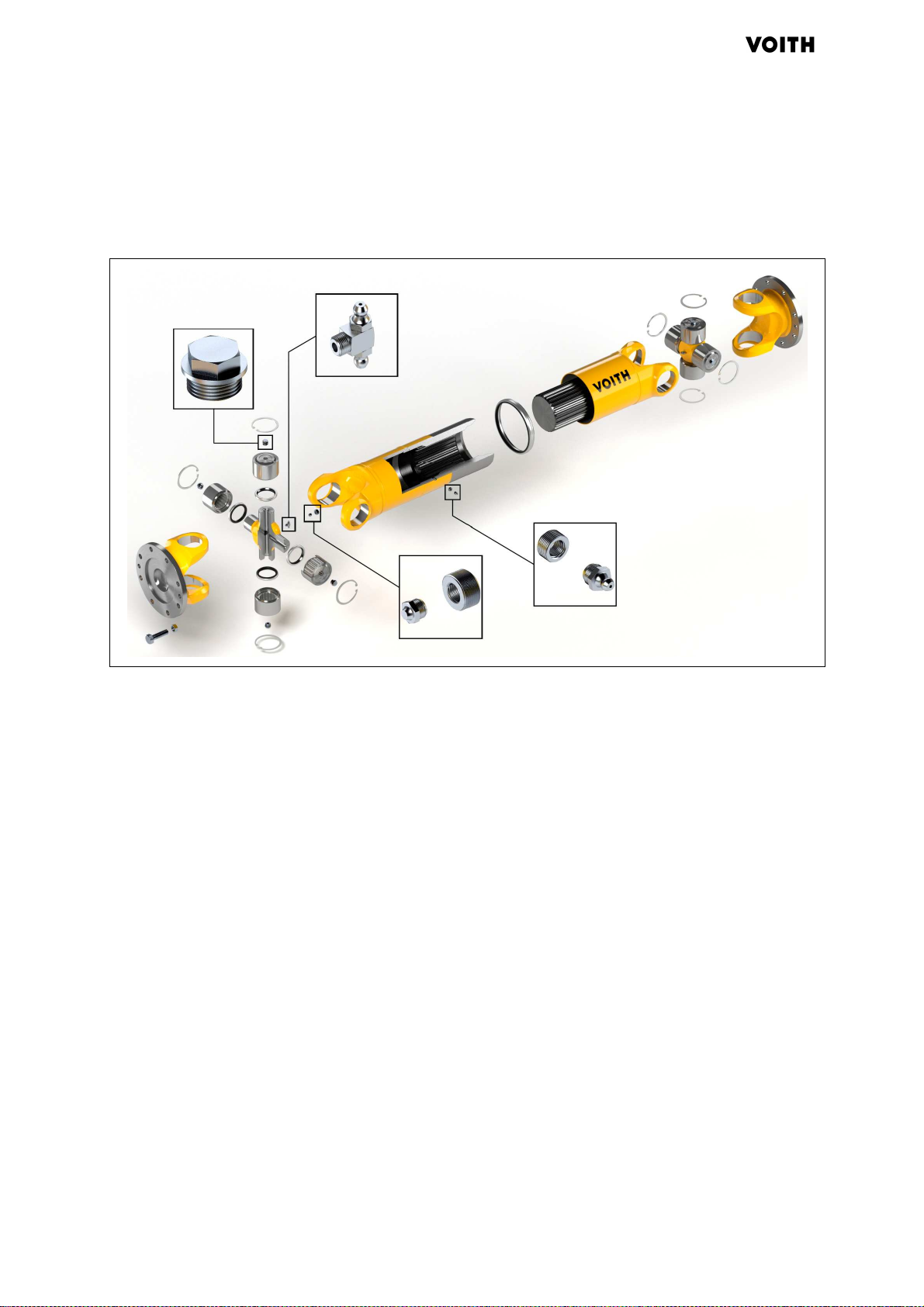
6.2.2 Transport universal joint shaft to the installation location
Fig. 6.3: Universal joint shaft
1 Screw 4 Grease/lubricating nipple N Zero marking, e.g. arrow
2 Connecting flange
(output, input side)
5 For telescopic lengths:
profile guard
Z1 Axial run-out
Z2 Radial run-out
3 Flange yoke 6 Screw plug
G853 en 07/2013, Version1
-performance universal joint shaft
44

J.M. Voith SE & Co. KG/VTA | Instruction Manual
High
Instruction manual (Translation)
For universal joint shafts with sliding part
Do not load profile guard (5).
1. Transport universal joint shaft to the installation location
( Chapter 4.3, page 30).
2. Remove transport braces.
3. Seal threaded holes of the transport braces with plugs.
Installation
6.2.3 Cleaning the universal joint shaft and connecting fla
For the cleaning of the universal joint shaft:
− Do not use any aggressive cleaning agents
− Do not clean seal elements and grease/lubricating nipple
with a high-pressure or steam cleaner.
1. Clean universal joint shafts and connecting flanges, that is,
centering and plane surfaces must be free of dirt, grease,
preserving agent, paint, and burrs.
2. Clean grease/lubricating nipples (4).
6.2.4 Checking, aligning, and fastening connecting flange
Do not use pry bars to turn the universal joint shaft in the joint
since otherwise bearing seals and the grease/lubricating
nipple could be damaged.
The universal joint shaft must be arranged so that the key
profile is protected against dirt and humidity. If possible,
installation should be so that the opening of the profile guard
(seal) points downward.
nge
If two or more universal joint shafts are arranged next to one
another, it is recommended that you install them turned by
90° to one another. Thus the mass acceleration torques
caused by the cardan error of the universal joint shaft center
part toward the outside are negated at least somewhat.
1. Check the connecting flange for roundness and true axial run
out ( Tab. 6.1, page 37).
2. Align and fasten the connecting flange to the universal joint
shaft according to the installation situation ( system
documentation).
G853 en 07/2013, Version1
-performance universal joint shaft
45

Installation
High
Instruction manual (Translation)
Speed [min
-
1
] Max. differential angle [°]
Speed [min
]
J.M. Voith SE & Co. KG/VTA | Instruction Manual
6.2.5 Checking the differential angle of the front faces of the connecting flange (with Z
arrangement)
0.5°
0.5°
Fig. 6.4: Checking the difference in joint angle between the faces of the
connecting flanges
1. Checking the difference in joint angle between the faces of the
connecting flanges:
< 1500 0.5
> 1500 Fig. 6.5, page 46
Tab. 6.3: Permissible differential angle (with Z arrangement)
2. In case of deviation: Realign connecting flange
0.5
0.4
0.3
0.2
0.1
Differential angle [°]
0
0 500 1000 1500 2000 2500 3000
Fig. 6.5: Permissible differential angle (with Z arrangement)
-1
G853 en 07/2013, Version1
46
-performance universal joint shaft

J.M. Voith SE & Co. KG/VTA | Instruction Manual
High
Instruction manual (Translation)
Speed [min
-
1
] Max. differential angle [°]
Installation
6.2.6 Checking the differential angle of the front faces of the connecting flange (with W
arrangement)
1. Checking the difference in joint angle between the faces of the
connecting flanges:
< 1500 0.5
> 1500 on request
Tab. 6.4: Permissible differential angle (with W arrangement)
2. In case of deviation: Align connecting flange with alignment
tips.
6.2.7 Bolting together the universal joint shaft and the connecting flange
Check that the contact surface of the bolts and nuts are bare
metal, clean, flat, burr-free, and at a right angle to the hole.
During assembly of the universal joint shaft, make sure that
the zero markings (N) are on a single plane
(Fig. 6.5, page 44).
With several moving parts, make sure that the components
are machted marked, so they cannot be confused.
Balancing weights may not be removed or shifted.
DANGER
While working on the universal joint shaft of vehicles, severe
injuries can result if the vehicle starts to move!
Secure vehicle against starting up/moving.
Standard designs of the universal joint shaft flange are selfcentering thanks to advance and rebound.
Begin installation with the input side connecting flange.
G853 en 07/2013, Version1
-performance universal joint shaft
If as a result of inexact position of the holes there are difficulties
during installation:
Do not re-bore holes or enlarge them in order to prevent an
impermissibly high area pressure and thus a possible failure
of the connection.
Replace flawed part.
47

Installation
High
Instruction manual (Translation)
Threaded connection
Blind hole connection
J.M. Voith SE & Co. KG/VTA | Instruction Manual
If you are using liquid locking agents such as "Loctite" or
"Omnifit": heed deviating tightening torques
( Manufacturer's instructions).
Do not use any lubricants that contain MoS2, e. g. Molykote
Tighten bolts in a diagonally opposite sequence.
The use of used nuts or bolts is not permitted.
To avoid cold welding and guarantee the testability of
the bolted
connection, heed the following:
When using the nut make sure that the surface with the
property class and company mark is visible. For self-locking
nuts, by contrast, the company mark may not be visible.
For a threaded connection:
1. Align the universal joint shaft with respect to the connecting
flange and slide onto the spigot.
2. If the bolt head has a stop or is flush with the fastening: if
necessary, tighten the bolt with screwdriver up to a snug
torque (approx. 0.3 MA) ( Tab. 6.1, page 37).
3. Tighten the bolts using a calibrated torque wrench, quickly and
without interruptions,to a tightening torque of MA.
For a blind hole connection:
crew stud bolts into blind hole (if using self-locking nuts
1. S
secure the male thread of the studs e.g. with Loctite 242.
Follow the special instructions of the manufacturer for blind
holes).
6.2.8 Final work
48
2. Align the universal joint shaft with respect to the connecting
flange and slide onto the spigot.
3. Thread on the nuts and using a calibrated torque wrench,
quickly and without interruptions to a tightening torque of MA.
Lubricate universal joint shaft (Chapter 9.4, page 61).
G853 en 07/2013, Version1
-performance universal joint shaft

J.M. Voith SE & Co. KG/VTA | Instruction Manual
High
Instruction manual (Translation)
6.3 Additional regulations for Hirth serration
For divided flange yokes:
Heed additional documentation (Mounting and dismounting
instructions for divided flange yokes).
Installation
Fig. 6.6: Seals for Hirth serration
1 O-seal (2x) 3 O-seal (optional)
2 Protective ring 4 Screw
5 Nut
1. If present: attach O-seal (3).
2. Attach O-seals (1).
3. Paint Hirth serration thinly with anti-seize (heed here that the
threaded and blind holes are free of anti-seize, otherwise the
friction value in the threads can be reduced by the anti-seize).
4. Heat up protective ring (2) to max. 80 °C and push onto
universal joint over Hirth serration.
If necessary: use hydraulic wrench.
. Tighten bolted connection with calibrated torque wrench cross-
5
wise in stages of 40%, 70%, and 100% of the prescribed
tightening torque:
G853 en 07/2013, Version1
− for Rota < 550 mm ( Tab. 6.1, page 37)
− for Rota > 550 mm (D
imensional drawing of the
universal joint shaft)
-performance universal joint shaft
49

Installation
High
Instruction manual (Translation)
Type
Universal joint shaft
∆ r
J.M. Voith SE & Co. KG /VTA| Instruction Manual
6.4 Additional regulations for use in paper machines
∆ a
Fig. 6.7: Checking radial offset and flange distance (with use in paper
machines)
∆ r Radial offset ∆ a Flange distance
Adhere to permissible radial offset and flange distance for
alignment of the input and output shafts when installing the
universal joint shafts:
length l
r
∆
[mm]
a
∆
[mm]
[mm]
Standard < 800 ± 2 ± 2
Standard 800–1500 ± 3 ± 3
Standard 1500–2500 ± 4 ± 4
Standard > 2500 ± 5 ± 5
Tab. 6.5: Permissible radial offset and flange distance (for use in paper
machines)
Only use the bolts that are screwed into the associated
flange yoke.
50
G853 en 07/2013, Version1
-performance universal joint shaft

J.M. Voith SE & Co. KG/VTA | Instruction Manual
High
Instruction manual (Translation)
7 Commissioning and operation
7.1 Commissioning the universal joint shaft
Check position of the individual parts to one another: the zero
marking (N) must be in a single plane.
Tighten the bolts (1) with tightening torque MA ( Tab. 6.1,
page 37).
In areas subject to explosion (atmosphere), only use ATEXcertified universal joint shafts. Here, heed certification ( Chapter
3.1, page 22).
In case of ATEX-certified universal joint shafts, it must be ensured
that
Commissioning and operation
The surface temperature in the field of joint bearings not
exceed 140°C.
Voith recommends at both joints, to attach a temperature
monitoring in the field of the joint bearings. ( Chapter 3.1,
page 22).
DANGER
Severe to deadly injuries due to rotating parts!
Attach guards ( system documentation).
Lubricate telescopic center section of universal joint shafts
that were stored for a longer time before commissioning in
the shortest operating position (Chapter 9.4, page 61).
Before commissioning, check whether all attached transport
braces have been removed.
G853 en 07/2013, Version1
-performance universal joint shaft
51

Commissioning and operation
High
Instruction manual (Translation)
7.2 Operating the universal joint shaft
Universal joint shaft checked ( Chapter7.1, page 51)
Guards attached ( system documentation)
DANGER
Severe to deadly injuries due to rotating parts!
Keep personnel who are not participating away, e.g. using
supervisory personnel, enclosures, fences.
Do not remove any safety equipment as long as the universal
joint shaft/system is not standing still and secured against
starting up again.
Before restarting the universal joint shaft/system, reattach all
safety equipment.
J.M. Voith SE & Co. KG /VTA| Instruction Manual
Perform regular visual inspections, e.g. for damage,
conspicuity.
Monitor operating noises for change. Report changes to the
responsible office/person.
DANGER
In case of ATEX-certified universal joint shafts: severe to
deadly injuries due to overheating universal joint shaft in
case of:
• Vibrating or oscillating universal joint shaft
• Exceeding of the life span
• Overload of the universal joint shaft
Avoid vibrations and oscillations during operation
Heed life span of the universal joint shaft
( Chapter 9.6, page 64)
Only operate the universal joint shaft within the specified
speed and torque range.
( Dimensional drawing of the system documentation)
Adhere to specific shaft angle.
( Dimensional drawing of the system documentation)
G853 en 07/2013, Version1
-performance universal joint shaft
52

J.M. Voith SE & Co. KG/VTA | Instruction Manual
High
Instruction manual (Translation)
8 Eliminating errors
The operator's service personnel may only perform the work for
eliminating errors described in this instruction manual.
Additional measures to eliminate errors may only be performed by the
manufacturer's service personnel or by service personnel authorized
by the manufacturer.
DANGER
Severe to deadly injuries due to rotating parts!
Secure drive against starting up.
Keep personnel who are not participating away, e.g. using
supervisory personnel, enclosures, fences.
Do not remove any safety equipment as long as the universal
joint shaft/system is not standing still and secured against
starting up again.
Eliminating errors
Before reastarting the universal joint shaft/system, reattach all
safety equipment.
DANGER
While working on the universal joint shaft of vehicles, severe
injuries can result if the vehicle starts to move!
Secure vehicle against starting up/moving.
G853 en 07/2013, Version1
-performance universal joint shaft
53

Eliminating errors
High
Instruction manual (Translation)
Error
Cause
Action
in the area around
J.M. Voith SE & Co. KG/VTA | Instruction Manual
The errors refer to increased values as compared to normal
operation.
Strong vibrations Insufficient roundness
and true axial run out
of the connecting
flange
Worn telescopic part Checking deflection play of the center part
Loose bolted
connections or
connecting flange
Imbalance Remove universal joint shaft ( Repair
Remove universal joint shaft (Repair instructions/system
documentation).
Check the connecting flange for roundness and axial run
out (Tab. 6.1, page 37).
If necessary, realign connecting flange.
( Chapter9.3.2, page 59).
Remove universal joint shaft ( Repair
instructions/system documentation).
Check connection, universal joint shaft flange, and
centering for damage (Chapter 6.2.7, page 47).
Replace bolts.
instructions/system documentation).
Check connection, universal joint shaft flange, and
centering for damage and run-out
(Chapter 6.2.7, page 47).
High temperature
the universal
joints
Damaged journal
cross set
Insufficient lubrication
Tab. 8.1: Eliminating errors
Only have universal joint shafts balanced by the
manufacturer's service personnel or by service personnel
authorized by the manufacturer.
Remove universal joint shaft ( Repair
instructions/system documentation).
Replace journal cross set ( Repair instructions).
Insofar as provided: Only have universal joint shaft
balanced by the manufacturer's service personnel or by
service personnel authorized by the manufacturer.
Lubricate universal joint shaft (Chapter 9.4, page 61).
G853 en 07/2013, Version1
54
-performance universal joint shaft

J.M. Voith SE & Co. KG/VTA | Instruction Manual
High
Instruction manual (Translation)
9 Maintenance
The operator's service personnel may only perform the maintenance
work and inspections described in this instruction manual. Other
maintenance work (especially overhauls) may only be performed by
the manufacturer's service personnel or personnel authorized by the
manufacturer.
DANGER
Severe to deadly injuries due to rotating parts!
Secure drive against starting up.
Keep personnel who are not participating away, e.g. using
supervisory personnel, enclosures, fences.
Do not remove any safety equipment as long as the universal
joint shaft/system is not standing still and secured against
starting up again.
Maintenance
Before restarting the universal joint shaft/system, reattach all
safety equipment.
DANGER
While working on the universal joint shaft of vehicles, severe
injuries can result if the vehicle starts to move!
Secure vehicle against starting up/moving.
WARNING
Injuries due to sharp-edged, falling, swinging, rolling parts!
Wear safety helmet, safety shoes, safety glasses, gloves, and
fall protection.
G853 en 07/2013, Version1
-performance universal joint shaft
55

Maintenance
High
Instruction manual (Translation)
J.M. Voith SE & Co. KG/VTA| Instruction Manual .
9.1 General notes about the maintenance and inspection of universal joint
shafts
The user or operator must heed the legal safety regulations
and take suitable preventative measures before starting
maintenance work.
The universal joint shafts may not be separated at the key
profile and exchanged for one another since the balancing
quality will be impermissibly compromised.
Flange bolted connections must be checked for tightness and
if necessary re-tightened to the prescribed torque.
To prevent impairment the balancing quality as well as a
source of ignition, dirt accumulations must be removed
periodically.
If universal joint shafts are cleaned with a high-pressure
device, seal elements may not be cleaned with the direct
stream. A re-lubrication after cleaning is recommended.
Universal joint shafts will be delivered painted on request. For
re-working of the painting, we recommend our standards.
Please contact us about this.
During color spraying of the universal joint shaft, attention
must be paid that the area where the profile or the seal
slides, is protected against color application. The same
applies for the grease/lubrication nipple, the ventilation
valves, the contact surfaces of the bolted connections, the
flange and the centering surfaces.
G853 en 07/2013, Version1
-performance universal joint shaft
56

J.M. Voith SE & Co. KG/VTA | Instruction Manual
High
Instruction manual (Translation)
Maintenance work or inspection
telescopic part
telescopic part
Lubrication intervals
9.2 Intervals for maintenance and inspections
The following intervals are guide values.
Adapt intervals to the respective operating conditions.
Agree on longer intervals with the manufacturer.
Before longer downtimes, lubricate all lubrication points.
For 3-shift operation or in case of heavy loading of the seals,
lubricate monthly. This may be necessary in roller mills due
to the special operating conditions (e.g. water, steam,
cinders, dust).
In case of use in paper machines with permanent operation,
lubricate the universal joint shafts every two months.
Interval
Maintenance
One-time after
1 Lubricate universal joints ( Chapter 9.4.2, page 61).
installation
After every 200
operating hours
1 Lubricate universal joints ( Chapter 9.4.2, page 61).
2 Perform visual inspection, e.g. for damage, noteworthy changes, and
especially the sealing seat of the lubrication nipple. Replace in case of
leaks.
3 Check bolted connections and connecting flange for tightness.
Re-tighten bolted connections if necessary ( Tab. 6.1, page 37).
4 For universal joint shafts with center part: lubricate
( Chapter 9.4.2, page 61).
5 Check maximum service life of ATEX-certified universal joint shafts (
Chapter 9.6, page 64).
Every 6 months 1 Check bolted connections and connecting flange for tightness.
Re-tighten bolted connections if necessary ( Tab. 6.1, page 37).
2 Perform visual inspection, e.g. for damage, noteworthy changes, and
especially the sealing seat of the lubrication nipple. Replace in case of
leaks.
Checking axial clearance of the journal cross set
( Chapter 9.3.1, page 58).
Annually 1 Check date for the next main overhaul of ATEX-certified universal joint
G853 en 07/2013, Version1
-performance universal joint shaft
Checking deflection play of the center part ( Chapter 9.3.2, page 59).
3 For universal joint shafts with center part: lubricate
( Chapter 9.4.2, page 61).
shafts ( Chapter 3.1, page 22)
2 Recommendation: lubricate length compensation with Rilsan coating
once a year for safety ( Chapter 9.4.2, page 61).
57

Maintenance
High
Instruction manual (Translation)
J.M. Voith SE & Co. KG/VTA | Instruction Manual
After several years,
depending on load
In case of unusual
running noises:
1
Have main overhaul done by the manufacturer.
If necessary, order new universal joint shaft.
1 Perform visual inspection, e.g. for damage, noteworthy changes
Checking axial clearance of the journal cross set
( Chapter 9.3.1, page 58).
Checking deflection play of the center part ( Chapter 9.3.2, page 59).
Determine cause, e.g. insufficient connection or other sytsem parts are
touching the universal joint shaft, e.g. hoses or cables.
If possible, eliminate the cause or consult the manufacturer.
Tab. 9.1: Intervals for maintenance work and inspections
9.3 Inspections
9.3.1 Checking axial clearance of the journal cross set
The measured values specified in this section are examples.
Binding measured values for each universal joint shaft type:
see repair instructions.
Heed force for lifting the universal joint shaft:
max. 1.5 x weight of the universal joint shaft.
Fig. 9.1: Checking axial clearance of the journal cross set on two levels
G853 en 07/2013, Version1
1. On the first universal joint:
et holder on the flange of the flange yoke.
− S
-performance universal joint shaft
58

J.M. Voith SE & Co. KG/VTA | Instruction Manual
High
Instruction manual (Translation)
Speed [min
-
1
]
Max. axial clearance [mm]
− If possible, remove bearing cover and apply the dial gauge
− Lift the universal joint shaft with a crane and read the
2. Check measurement values:
< 500 0.20
500–1500 0.06
> 1500 0.03
Tab. 9.2: Checking axial clearance of the journal cross set
3. If exceeded:
Use thicker locking rings to reduce the axial clearance (order
repair instructions).
Maintenance
to the front face of the journal cross. Otherwise apply the
dial gauge to the bottom of the bearing.
measured value from the dial gauge.
Send universal joint shaft to manufacturer.
Insofar as provided: Only have universal joint shaft balanced
by the manufacturer's service personnel or by service
personnel authorized by the manufacturer.
9.3.2 Checking deflection play of the center part
Fig. 9.2: Checking deflection play of the center part
G853 en 07/2013, Version1
-performance universal joint shaft
1. Measure the length “a” of the spline profile on the top and mark
the middle.
2. Position the universal joint shaft precisely at the installation
length and put under neath.
59

Maintenance
High
Instruction manual (Translation)
Speed [min
-
1
] Max. deflection
ratio
c
J.M. Voith SE & Co. KG/VTA | Instruction Manual
Fig. 9.3: Reading off deflection dimension
3. Apply dial gauge and set scale to "0."
4. Measure distance b from the measurement point to the middle
of the key profile.
Heed force for lifting the universal joint shaft: max. 1.5 x
weight of the universal joint shaft.
5. Lift the universal joint shaft and read the measured value from
the dial gauge.
6. Calculate deflection ratio K:
K =
c
b
Example:
imension b = 300 mm Dimension c = 0.36 mm
D
deflection ratio 0,0012
K ==
mm 0,36
mm 300
< 500 0.004
> 500 0.003
Tab. 9.3: Permissible deflection ratio
If exceeded:
Send universal joint shaft to manufacturer.
G853 en 07/2013, Version1
-performance universal joint shaft
60

J.M. Voith SE & Co. KG/VTA | Instruction Manual
High
Instruction manual (Translation)
9.4 Lubrication
9.4.1 Lubricants
Suitable for the lubrication of the universal joint shaft are greases
that meet the requirements for the identification KP 2 K according
to DIN 51825, e.g. "Renolit PEP 1/2" from Fuchs. For our CH and
E series, we recommend Wear Care 500, which can also be mixed
with other greases.
For other greases: consult the manufacturer.
No lubricants with MOS2 additives may be used.
9.4.2 Lubricating the universal joint shaft
DANGER
Maintenance
Danger of slipping on escaped lubricants!
Wear safety shoes with slip-proof, oil-resistant soles, safety
glasses, safety helmet, and fall protection.
Remove escaped lubricants as soon as possible.
For center parts with (plastic-coated) Rilsan spline profile,
application related re-lubrication is required. Please contact
the manufacturer.
The ventilation valves may not be removed or replaced by
grease/lubricating nipples or other plugs.
Do not press in lubricant with hard knocks or too much
pressure (max. 15 bar) on the grease/lubricating nipple.
G853 en 07/2013, Version1
-performance universal joint shaft
61

Maintenance
High
Instruction manual (Translation)
J.M. Voith SE & Co. KG/VTA | Instruction Manual
Fig. 9.4: Lubrication points of the universal joint shaft
S1 Lubrication point (central on the journal cross)
S Lubrication point (for telescopic shafts)
S2 Lubrication point (for individual lubrication)
Re-lubricating the length compensation should, if possible,
always be done at the shortest operating position. If this is
not possible, the lubricant quantities specified in the following
table (Tab. 9.4, page 64) must be used. At least once a
year the universal joint shaft should be pushed slowly
together to the shortest operating length so that excess
grease can escape via the profile guard.
1. Put the universal joint shaft in the shortest oper
ating position.
2. Clean all lubrication points.
3. Lubricate bearings until the lubricant escapes from all seal lips
in order to ensure that
− the quantity of grease is sufficient
− any penetrated dirt is removed
− the seal lips are re-greased.
4. For telescopic lengths:
− If possible lubricate center part in the shortest operating
position until lubricant escapes via the seal of the profile
guard.
− If the center part cannot be put into the shortest operating
position, the lubricant quantity specified (Tab. 9.4, page
G853 en 07/2013, Version1
64), must be used for re-lubrication if nothing else is
specified on the dimensional drawing.
-performance universal joint shaft
62

J.M. Voith SE & Co. KG /VTA| Instruction Manual
High
Instruction manual (Translation)
Rota [mm]
Standard designs
Amount of grease [cm³]
198 RT 170
208 RT 40
250 RT 60
285 RT 80
Maintenance
RTL 40
RTK1 80
RTK2 50
RTL 70
RTK1 160
RTK2 110
RTL 80
RTK1 250
RTK2 150
315 RT 90
RTL 100
RTK1 210
RTK2 150
350 RT 140
RTL 180
RTK1 690
RTK2 480
390 RT 150
RTL 190
RTK1 950
RTK2 580
440 RT 220
RTL 280
RTK1 740
G853 en 07/2013, Version1
-performance universal joint shaft
RTK2 680
490 RT 340
RTL 430
RTK1 840
RTK2 770
550 RT 420
63

Maintenance
High
Instruction manual (Translation)
J.M. Voith SE & Co. KG /VTA| Instruction Manual
RTL 550
RTK1 1500
RTK2 1500
590 – 620 CHT / ET 590
650 – 680 CHT / ET 700
710 CHT / ET 960
740 – 800 CHT / ET 1100
830 – 860 CHT / ET 1500
890 – 920 CHT / ET 2000
950 – 1010 CHT / ET 2400
1040 – 1200 CHT / ET 3700
1220 – 1340 CHT / ET 4900
Tab. 9.4: Permissible lubricant quantity for the re-lubrication of standard
center parts.
The lubricant quantities, which is spefified in Tab. 9.4, page 64
relate to the center part and have to be divded by the number of
lubricant nipples.
9.5 Main overhaul
Performing of the main overhaul requires specialized knowledge.
We recommend having the manufacturer's specialized personnel
perform the main overhaul.
Please contact the manufacturer.
The screw plugs (6) are necessary for the overhaul of the universal
joint shaft.
Do not loosen the screw plugs (6) ( Fig. 6.3, page 44).
9.6 Life span of ATEX universal joint shafts
ATEX-certified universal joint shafts must be sent back for main
erhaul after expiration of the calculated life span ( see drawing
ov
in the system documentation), at the longest after 5 years. The date
for the next main overhaul is on the nameplate (Chapter 3.1, page
22).
G853 en 07/2013, Version1
-performance universal joint shaft
64

J.M. Voith SE & Co. KG/VTA | Instruction Manual
High
Instruction manual (Translation)
10 Removal
During removal of the universal joint shaft:
Heed additional documentation: (Chapter 1.3, page 8).
Prevent sliding apart of the telescopic length part.
Prevent a tipping over of the flange yoke when loosening the
flange connection.
Only remove universal joint shaft in areas not subject to explosion
(atmosphere).
DANGER
For specially-designed universal joint shafts, improper
installation and removal can cause severe injuries or even
death.
Removal
Heed and if necessary request additional documentation
( Chapter 1.3, page 8).
DANGER
Severe to deadly injuries due to rotating parts!
Secure drive against starting up.
Keep personnel who are not participating away, e.g. using
supervisory personnel, enclosures, fences.
DANGER
Severe to deadly injuries due to swinging or falling universal
joint shaft!
Heed common attachment regulations.
Only lift universal joint shaft at the prescribed attachment
points ( Fig. 4.1, page 32).
Do not attach universal joint shaft in marked area
( Fig. 4.1, page 32).
Only use sufficiently dimensioned and tested lifting appliance.
Secure danger zone under the universal joint shaft against
entry.
G853 en 07/2013, Version1
-performance universal joint shaft
Wear safety helmet, safety shoes, gloves, safety glasses, and
fall protection.
65

Removal
High
Instruction manual (Translation)
J.M. Voith SE & Co. KG/VTA | Instruction Manual
DANGER
In case of telescopic lengths: Severe to deadly injuries due to
falling parts!
Secure telescoping part against being pulled apart, e.g. with a
suitable rope.
DANGER
In case of ATEX-certified universal joint shafts: severe to
deadly injuries due to spark formation in case of:
• Equipotential bonding
• Impact-like touching of adjacent metal parts
• Slipping screw drivers
• Hammer blows
Only remove universal joint shaft in areas not subject to
explosion (atmosphere).
DANGER
Severe crushing or crushing of limbs due to tipping universal
joint!
Secure universal joints against tipping, e.g. with a suitable
rope or wedge.
Never reach between the universal joint, even if there is a
deflection guard present.
DANGER
Severe to deadly injuries due to rolling universal joint shaft!
Only set universal joint shaft down on suitable bases.
Secure universal joint shaft against rolling away.
G853 en 07/2013, Version1
-performance universal joint shaft
66

J.M. Voith SE & Co. KG/VTA | Instruction Manual
High
Instruction manual (Translation)
Damage
Damage diagnosis
Returning
11 Repair
Repairs may only be made by the manufacturer's service
personnel or personnel authorized by the manufacturer
Only repair universal joint shaft in areas not subject to explosion
(atmosphere).
DANGER
In case of ATEX-certified universal joint shafts: severe to
deadly injuries due to spark formation in case of:
• Equipotential bonding
• Impact-like touching of adjacent metal parts
• Slipping screw drivers
• Hammer blows
Repair
Only repair universal joint shaft in areas not subject to
explosion (atmosphere).
If there is damage, first determine the cause of the damage
and eliminate it.
To determine the cause of damage, consult service
personnel authorized by the manufacturer.
Exact damage diagnosis requires great experience. We
recommend that you send the universal joint shaft to the
manufacturer unassembled.
You will receive a damage report and a cost suggestion for a
repair. You decide whether the repair is worthwhile or whether the
universal joint shaft will be replaced. If desired, the manufacturer
will handle the disposal of the old universal joint shaft.
Prepare defective universal joint shafts for returning as follows:
Secure in a wooden crate with suitable blocking.
Include a report with details about cause of damage, if
known.
12 D
G853 en 07/2013, Version1
-performance universal joint shaft
isposal
Dispose of universal joint shaft in accordance with the locally-
applicable regulations or send the defective universal joint
shaft to the manufacturer.
Dispose of operating and hazardous materials separately
according to the locally-applicable regulations. Heed the
manufacturer's safety data sheets.
67

Declaration of incorporation
High
Instruction manual (Translation)
13 Declaration of incorporation
We,
J.M. Voith SE & Co. KG/VTA
Alexanderstraße 2
89510 Heidenheim
hereby declare that the
machine called: High-performance universal joint shaft
in the series S,R,CH,E
corresponds insofar as possible given the scope of delivery to the
essential health and safety requirements as per Annex I of
Directive 2006/42/EC (Machinery Directive).
Other directives and harmonized standards applied, particularly
DIN EN ISO 14121, DIN EN ISO 12100-1, DIN EN ISO 12100-2.
J.M. Voith SE & Co. KG /VTA| Instruction Manual
Moreover, we declare that relevant technical information for this
partly completed machinery has been issued as per Annex VII Part
B. We undertake to transmit in response to a reasoned request by
the national authorities, relevant technical information on the partly
completed machinery.
The method of transmission will be agreed with the national
authorities.
You may request the relevant technical information from the
person authorized for technical information at
J.M. Voith SE & Co. KG/VTA
Mrs. Gudrun Mißlbeck
Alexanderstraße 2
89510 Heidenheim
The partly completed machinery must not be put into service until the
final machinery into
which it is to be incorporated has been declared in conformity with the
provisions of Machinery Directive 2006/42/EC, where appropriate.
Making changes to the machinery, unless J.M. Voith SE & Co. KG/VTA
gave their
express written approval, is not permitted.
Heidenheim, July 15, 2013
Dr. Jerry Mackel
G853 en 07/2013, Version1
Manager of the product group
-performance universal joint shaft
68

J.M. Voith SE & Co. KG/VTA | Instruction Manual
High
Instruction manual (Translation)
14 Declaration of conformity
For ATEX certified universal joint shafts
We
hereby declare that the device,
caled: High-performance universal joint shaft
in the series S,R,CH,E in ATEX design
corresponds to the essential health and safety requirements as per
Annex II of
of the Council of the European Community.
Declaration of conformity
J.M. Voith SE & Co. KG/VTA
Alexanderstraße 2
89510 Heidenheim
Directive 94/9/EG
Other directives and harmonized standards applied, particularly
EN 13463-1: 2009 EN 13463-5: 2011
The labeling of the device includes the following information:
II 2GD c T3/T4
y Changes to the device, except with express written approval
B
from Voith Turbo this declaration loses its validity.
Heidenheim, July 15, 2013
G853 en 07/2013, Version1
Dr. Jerry Mackel
Manager of the product group
-performance universal joint shaft
69

Index
High
Instruction manual (Translation)
15 Index
J.M. Voith SE & Co. KG/VTA | Instruction Manual
B
Basic safety information 13
Bolts
Dimensions 36, 37
Property class 41
C
Checking
xial clearance 58
A
Deflection play 59
W arrangement 47
Z arrangement 46
Checking the delivery 29
Commissioning 51
Connecting flange
Dimensions 36
D
Damage 67
Damage diagnosis 67
Declaration of conformity 69
Declaration of incorporation 68
Disposal 67
Documents
additional 9
other applicable 8
F
Fixed length universal joint shaft
3
2
Flange yoke 22
H
Hirth serration
Additional regulations 49
I
Inspection
Axial clearance 58
Deflection play 59
Installation 35
flange bolted connections 35
Hirth serration 49
Paper machines 50
Involute profile 22
J
Joint shaft
orque transmission 27, 28
T
L
Link head 22
L
ubricants 61
Lubrication 61
Lubrication intervals 57
M
Main overhaul 64
aintenance 55
M
Intervals 57
Malfunctions
Remedy 53
Markings 10
O
Operation
Universal joint shafts 51
Other applicable documents 8
P
Packaging 29
Paper machines
Additional regulations 50
Personnel
Duties 17
Preservation 34
Product observation 7
Product safety 13
R
Repairs 67
S
Safety equipment
rsonal 21
Pe
Safety information
Commissioning and operation
19
Decommissioning 20
Disposal 20
Installation 18
Maintenance work and
inspections 20
Operator 15
Personnel 17
Preservation 18
Product safety 13
Proper use 13
Remaining risks 14
Removal 20
Repair 20
Transport 18
G853 en 07/2013, Version1
-performance universal joint shaft
70

J.M. Voith SE & Co. KG/VTA | Instruction Manual
High
Instruction manual (Translation)
Index
Safety instructions
Personal protective
equipment 21
Safety symbols 12
Series 26
Spare parts 21
Staff
Qualification 16
Storage 33
Symbols 10
T
Target groups 7
elescopic length 22, 23
T
Standard center part 22
Tripod center part 23
Threaded connections
Bolted connections 35
Connecting flange 35
Transport
Fork lift 30
Truck/crane 30
U
Universal joint shaft
Application 25
Installation 35
Lubrication 61
Maintenance 55
Preservation 34
Repair 67
Series 26
Storage 33
Structure 22
W arrangement 25
Z arrangement 25
Unpacking 29
Use
Improper 13
Misuse 13
Proper 13
W
W arrangement 25
Warning 11
Warnings
Danger levels 11
Safety symbols 12
Warranty 17
Z
Z arrangement 25
G853 en 07/2013, Version1
-performance universal joint shaft
71

High
Instruction manual (Translation)
J.M. Voith SE & Co. KG/VTA
Universal joint shafts
Alexanderstr. 2
89510 Heidenheim, Germany
Telephone +49 7321 37-8283
Fax +49 7321 37-7106
UJShafts@Voith.com
www.voith.com
J.M. Voith SE & Co. KG/VTA | Instruction Manual
G853 en 07/2013, Version1
Engineered reliability.
-performance universal joint shaft
 Loading...