

Page 1
VOI
A
NALOGUE
A
DAPTER
SPEED
V-6017
1 VOI
User Manual
SPEED
V-6017
Page 2

© 2007 Voispeed Ltd. – All rights reserved.
Total or partial reproduction of this document is prohibited without prior written consent of
the publisher. Such consent will only be granted in those instances when the source of
the document is clearly stated.
Revision: 1.0 Released on: 08/10/2007
Declaration of conformity can been found at this internet address:
http://www.voispeed.com/products/conformity/V-6017DDC.pdf
U
SER MANUAL
© VOI
SPEED LTD
.
2
Page 3

1 - Index
1 - Index .......................................................................................................................3
2 - Introduction............................................................................................................4
3 - Security information..............................................................................................4
3.1 - Product Disposal ................................................................................................ 5
3.2 - Product Warranty ............................................................................................... 5
4 - General Information ..............................................................................................7
4.1 - General specifications .......................................................................................7
4.2 - LEDs ....................................................................................................................7
4.3 - Main functionalities ............................................................................................ 8
4.4 - List of components in the package................................................................... 8
5 - Getting started .......................................................................................................8
5.1 - Mounting Instructions ........................................................................................ 8
5.2 - Requirements...................................................................................................... 9
5.3 - Installation........................................................................................................... 9
5.4 - Emergency Line................................................................................................ 10
6 - Manual Setting .....................................................................................................10
7 - Web Interface .......................................................................................................11
7.1 - Current Status................................................................................................... 12
7.2 - Basic Options ................................................................................................... 13
7.3 - Network ............................................................................................................. 13
Call 15
System .............................................................................................................................. 16
7.4 - Admin Options.................................................................................................. 16
Upgrade............................................................................................................................. 16
System .............................................................................................................................. 16
Reset default ..................................................................................................................... 17
7.5 - FXO Port............................................................................................................ 17
Account ............................................................................................................................. 17
SIP 18
Voice 20
PSTN & Dial ...................................................................................................................... 21
3
© VOI
SPEED LTD
.
VOI
SPEED
V-6017
Page 4
2 - Introduction
Welcome to VOIspeed V-6017 user manual. We would like to thank you for your
purchase and for having chosen one our products. This manual provides general
guidelines for a correct use of the product. In case you require further information on this
product or to receive technical assistance please visit our website:
www.voispeed.com.
3 - Security information
Please read the security rules below that you should follow when using this device.
Please comply with these guidelines to avoid taking unnecessary risks.
Use the device only in the standard working position.
Any installations or repairs on the product should be carried out only by
qualified and fully trained personnel.
Use only accessories that are fully approved by The Manufacturer. Do not
connect to any non compatible products.
The device is not waterproof. Avoid contact with liquids.
If you connect the device to other devices please read the user guide of the
new equipment first. Do not connect the device to any non compatible
products.
Avoid prolonged exposure to direct sunlight. Do not place the device near
sources of intense heat (e.g. radiators, fire, etc.) and near electronic
equipment producing strong magnetic fields (speakers, microwaves ovens,
etc.). Do not install the device in humid rooms and avoid contact with liquids.
Do not expose the device to aggressive gas and do not use it in too dusty
environments. Never use the device in presence of any explosive gas (e.g.
methane). Refrain from opening any parts of the product and do not touch the
plugs with metal or sharp objects.
Please make sure that the power supply complies with the voltage setting of
your equipment. If you have any doubts about the voltage setting, please call
the technical support. Do not remove any security devices. Always
disconnect the telephone from the power supply during storms. All
maintenance work should be carried out by qualified personnel.
We suggest cleaning the equipment only using a slightly dump cloth.
U
SER MANUAL
© VOI
SPEED LTD
.
4
Page 5

3.1 - Product Disposal
Our products are compliant with the European Directives
2002/95/CE, 2002/96/CE and 2003/108/CE regarding the limitation
of use of lead, mercury, cadmium, chromium (VI) as well as some
flame retardants and hazardous material within electric and
electronic equipment and disposal.
The sign above representing a crossed waste bin indicates that the product, once no
longer utilised, must be disposed of by separating it from any normal waste
must ensure that the product, once reached its end-life, is given to qualified organisations
responsible for the collection of electronic and electrical waste. The user may otherwise
choose to return the equipment to the manufacturer when purchasing a new equivalent
device. In this case the product returned must correspond to the one being purchased.
Suitable disposal of the equipment in accordance with relevant recycling guidelines helps
the environment and fosters sustainable development. Unlawful disposal of this
equipment is an offence and may lead to prosecution in accordance with the Country’s
laws in which the disposal takes place.
Correct disposal benefits us and the environment.
. The user
3.2 - Product Warranty
The Manufacturer (Harpax Srl.) warrants its products to be free from defects in material
and workmanship during the warranty period. The product is covered by warranty only if it
is used in compliance with the guidelines contained in this manual. This warranty will be
invalidated in case of manumission, wrong use of the product or accidental damage. This
product is compliant with CE regulations.
The warranty period starts from the date the product has been purchased (stated on the
invoice) and will last for twelve (12) months thereafter. If a product proves to be defective
in material or workmanship during the warranty period, The Manufacturer will, at its sole
discretion, repair or replace the product with a similar one (new or re-conditioned). The
replacement unit will be covered by a new warranty period that will last the remaining time
on the customer's original limited warranty. The old equipment substituted will
automatically become property of Harpax Srl.
In order to have access to the warranty the user must fill out the online form that can be
found on
customer support department on 01727 848186). The user must provide a valid invoice to
claim warranty on the product.
www.prontopbx.com or www.voispeedltd.com (please also contact the
5
© VOI
SPEED LTD
.
VOI
SPEED
V-6017
Page 6

Exclusions.
The warranty will be invalidated in the following cases:
• Damages to any parts that are meant to ware out with time. No support,
maintenance or replacement will be provided for these components.
• Damages resulting from using a wrong power supply.
• Damages resulting from misuse or actions that do not comply with the
guidelines of this manual.
• Damages resulting from lack of maintenance as advised by The Manufacturer.
• Damages resulting from installing or using the product without complying with
the relevant standards (legal, health and safety, technical, etc.) that are in place
in the Country where the product is utilised.
• Damages resulting from misuse, negligence, unauthorized product modification,
repair or attempted repair by anyone not authorized by The Manufacturer
(including the user) or failure to follow instructions supplied with the product.
• Damages caused during product transportation or delivery due to insufficient or
inappropriate packaging.
• Damages caused by accident, fire, water, any acts of nature, insufficient
ventilation or other causes that don not fall under the control of The
Manufacturer.
• Damages caused from any unintentional or deliberate human acts.
• Damages caused from manumission or in conjunction with warranty labels being
broken.
• Damages to Software or any Hardware component not supplied by The
Manufacturer with the product.
This warranty is only valid within the European Community.
U
SER MANUAL
© VOI
SPEED LTD
.
6
Page 7

4 - General Information
The V-6017 is a stand-alone analogue gateway that can be connected directly to your
local area network. It provides two RJ11 ports to connect one external PSTN analogue
line (FXO) and one emergency analogue telephone (FXS). Thanks to the V-6017,
VOIspeed PBX can route calls over an external PSTN line with no need for additional PCI
analogue cards. With the V-6017, the analogue line becomes completely transparent to
the PBX. The PSTN line can be accessed by the PBX either as a traditional SIP carrier or
as a normal extension. Furthermore, the V-6017 benefits from an additional analogue
port to make emergency calls in case of power supply outages. The V-6017 is also
provided of an additional switch port that is particularly useful in case of multiple V-6017
installations or it can be used to connect another network device to the LAN. The V-6017
is reliable and extremely easy to configure.
4.1 - General specifications
Power supply
IN 110-240V AC
OUT 9V DC 600 mA
PC 1 10/100Base T RJ-45
LAN 1 10/100Base T RJ-45
Ports
FXO 1 RJ11 for PSTN line
FXS 1 RJ11 for emergency phone
Power < 2.5 W
Operating temperature 0~400C
Operating humidity 10~95%
Dimensions 101mm*101mm*31mm
Weight 423g
4.2 - LEDs
There are four LEDs mounted on the V-6017. They display the status of the resources
connected to the device. The table below reports the colours associated to each resource
status:
POWER ON OFF Flashing Green
LAN Not Connected Connected Data flow
PC Not Connected Connected Data flow
FXO Not In Use - In Use
FXS Not In Use - In Use
7
© VOI
SPEED LTD
.
VOI
SPEED
V-6017
Page 8

4.3 - Main functionalities
• VoIP protocols: SIP 2.0 (RFC3261, RFC3262, RFC3264, RFC3265).
• SDP (RFC2337)
• DTMF standard: in Audio, RFC2833 and SIP info.
• Voice Codec: G.711 (A-law/U-law), G.729A/B, G.726-32, iLBC.
• 1 FXO port routing inbound and outbound calls over a traditional analogue
line (PSTN)
• 1 FXS port to connect an emergency phone to be used in case of power
outage.
• LED to display device status
• Stack mountable
• Internal switch (supporting DHCP and static IP address) connected to 2
RJ-45 ports 10/100BaseT.
• Network protocols: TCP/UDP/IP, HTTP, DHCP, FTP, DNS, ARP and ICMP.
• Standard encryption and authentication (DIGEST using MD5).
• The system can send event logs to an external Syslog server.
• Firmware upgrade through TFTP/FTP or HTTP.
• Date/time synchronisation using NTP server.
• Echo Canceller (G.168) and Jitter Buffer.
• Voice Activity Detection (VAD).
• Volume control over PSTN line.
• User defined setting of hang-up signalling.
• Caller-ID retention over PSTN.
4.4 - List of components in the package
• One V-6017 SIP adapter.
• One Ethernet UTP RJ45 CAT5 network cable, 1.5m length.
• One RJ-11 telephone cable, 2m length.
• Two supports for installation and stack configuration.
• One power supply 9V 600mA.
• User manual.
5 - Getting started
5.1 - Mounting Instructions
Together with the V-6017 you will find two plastic supports in the package. These are:
U
SER MANUAL
© VOI
SPEED LTD
.
8
Page 9
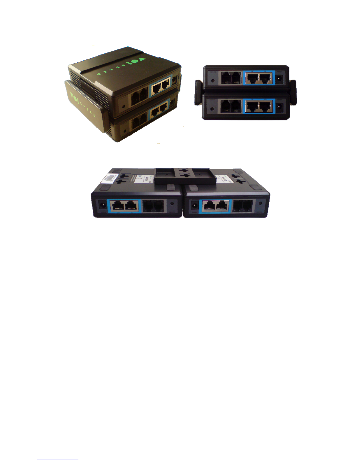
• Vertical mounting support:
• Wall mounting support:
These supports can also be used to connect the adapters in stack configuration, hence
saving space. In this case the adapters should be connected by plugging the LAN port of
one adapter into the PC port of the next one.
5.2 - Requirements
Before connecting the V-6017 adapter to the network, please make sure that both your
network and VOIspeed server are working correctly.
5.3 - Installation
Firstly, you will need to configure the network interface in order to configure the adpater
from web. As default, the adapter will query the DHCP server for a valid IP address as
soon as it is connected to the LAN. In order to find this address you need to use the vocal
menu (see also section 6 -Manual Setting).
In order to access the vocal menu’, you need to connect a telephone to the FXS port
(emergency port) and enter ‘***’. Use the button * to pass to the next item in the menu’. In
case there are problems with assigning an IP address or there is no DHCP server
connected to the network, the vocal message will provide a null IP address (i.e. 0.0.0.0).
In this instance the IP address will have to be configured manually following the steps
below:
- Enter 01 and then 9 to move to static mode.
- Enter 02 followed by the new IP address.
9
© VOI
SPEED LTD
.
VOI
SPEED
V-6017
Page 10

- Enter 03 followed by the mask net.
menu’
By entering the start key, the system will list all available options for that
By entering 01 the adapter will describe how the IP address is being
acquired: in static mode (entered during the setup phase) or in dynamic
mode (through a DHCP server). In order to change mode you need to
t the adapter once any changes have been
With this command the system will provide the IP address assigned to the
- Enter 04 followed by the gateway’s address.
- Enter 05 followed by the primary DNS server’s address.
Note:
IP addresses must be entered using 12 digits without dots. Example: to enter
192.168.0.15 you will need to enter 192168000015.
Once the IP address has been configured you can then enter the adapter’s web interface.
in order to simplify the configuration process we strongly recommend configuring
Note:
the web interface using a static IP address.
5.4 - Emergency Line
In addition to accessing the vocal menu’, the FXS port can be used to connect a
traditional analogue phone to be used as an emergency backup. The emergency phone
can be used in case of electric outage that would prevent the PBX from operating
correctly.
6 - Manual Setting
It is possible to setup the V-6017 adapter using an analogue telephone connected to the
FXS port. You will need to enter ‘***’ at the phone in order to access the configuration
menu followed by the desired option.
OPTION DESCRIPTION
#
Main Menu’
Here you can access all available options. Once entered any subyou can go back to the main menu’ by pressing the ‘#‘ key.
List of available options
*
menu’.
Network address static/dynamic
01
enter 9.
Note: you will need to restar
made.
IP address
02
adapter. This address can be easily changed by entering a new one.
U
SER MANUAL
© VOI
SPEED LTD
.
10
Page 11

03
sk assigned to the adapter. This
d by
be changed by
Provides the TFTP server’s IP address. The address can be changed by
entering a new one. The TFTP server is used to update the adapter’s
the option to reset the adapter. If
you enter 9 the adapter will reset without losing any previous setting. In
case you entered the adapter’s MAC address, the default setting will be
n be found in the label
underneath the adapter. You will need to apply the following coding in
Subnet Mask
The system will provide the subnet ma
parameter can be changed by entering a new one.
04
05
06
99
Gateway
Provides the IP address of the pre-defined gateway. It can be change
entering a new one.
DNS Server
Provides the DNS server’s IP address. This address can
entering a new one.
TFTP Server
internal firmware.
Reset
By entering 99 the system will give you
applied after reset.
Note: the MAC address is a 12 digit number that ca
order to decipher the number:
• A = 22
• B = 222
• C = 2222
• D = 33
• E = 333
• F = 3333
When entering a new IP address using any of the commands above, you will need to
enter a 12 digit number without dots. As an example, the number 192.168.1.10 will need
to be entered as ‘192168001010’. Similarly, to change the subnet mask into
‘255.255.255.0’ you will need to enter the option ‘03’ followed by ‘255255255000’.
7 - Web Interface
In order to access the web interface you will need to enter the string ‘http://’ followed by
the adapter’s IP address. It is important to note that the PC from which you intend to
access the web interface and the V-6017 adapter need to be connected to the same
11
© VOI
SPEED LTD
.
VOI
SPEED
V-6017
Page 12
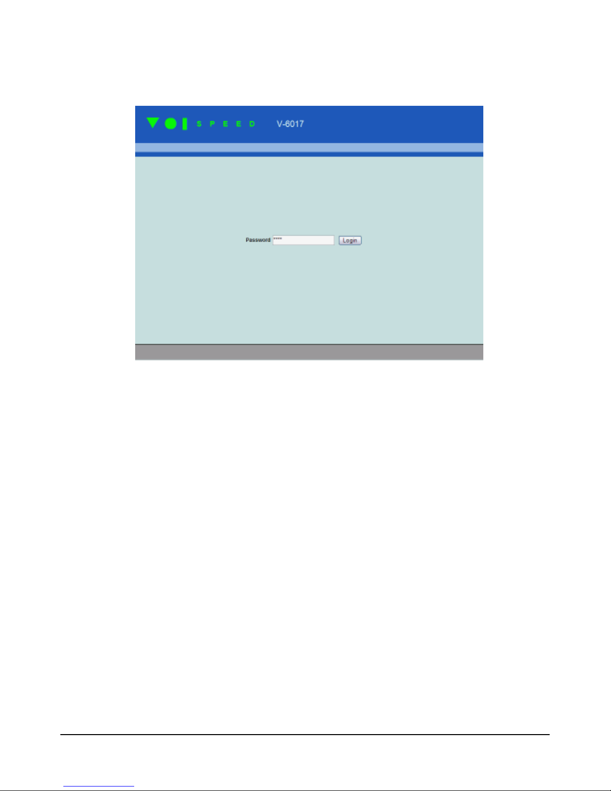
network. Please consult section 6 -Manual Setting in order to find out the adapter’s IP
address.
The default password to access the web interface is ‘voip’. We reccommend changing
this password at the first access.
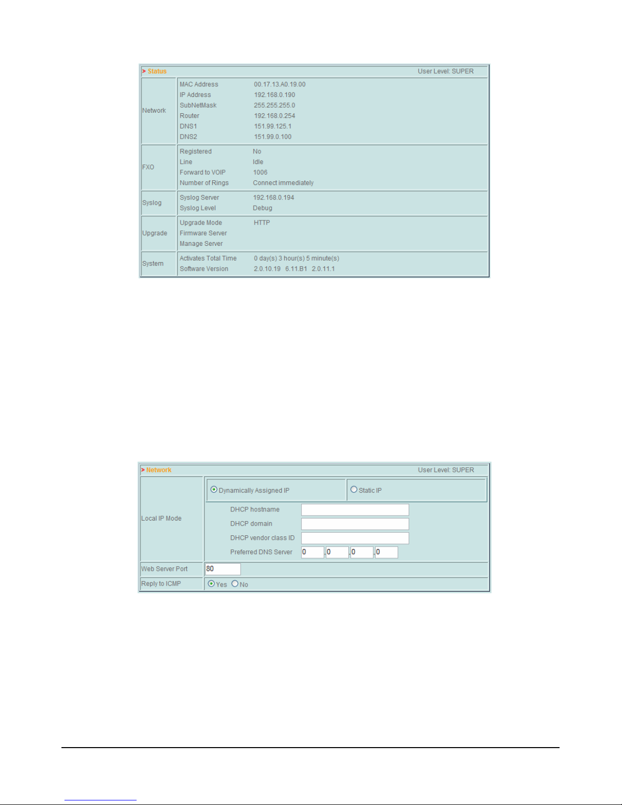
7.1 - Current Status
By pressing on current status the system will show a summary of the adapter’s settings.
Here you can also find the firmware’s version and when the adapter’s was restarted last.
U
SER MANUAL
© VOI
SPEED LTD
.
12
Page 13
7.2 - Basic Options
This option includes all main settings for the V-6017 including network and call interfaces.
7.3 - Network
In this section you can configure the LAN interface. This setting can be done
automatically by the DHCP server or entered manually. Browising the vocal menu
(section 6 -Manual Setting) you can determine the adapter’s IP address.
By selecting ‘Dynamically Assigned IP’ the LAN interface will be configured by the DHCP
server. You can also configure all the settings in order to increase the security of the
DHCP protocol. Please consult your network administrator for more information.
13
© VOI
SPEED LTD
.
VOI
SPEED
V-6017
Page 14

e a
network (it is usually
o IP
DHCP hostname Network name or DHCP server’s IP address.
Note: if this value is different from that negotiated with the DHCP
Here you can enter a different DNS server from that assigned by the
l in cases where ‘network
DHCP domain DCHP server’s domain.
DHCP vendor
DHCP server identifier.
class ID
server during setup, the adapter will refuse the connection.
Preferred DNS
DHCP server. The DNS server is usefu
server
names’ or URLs are entered in place of IP addresses.
: the adapter may not function properly and acquire the right IP address in case any
Note
of the above settings are not entered correctly.
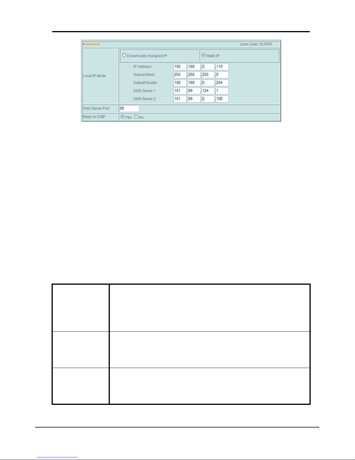
In case of absence of or problems with the DHCP server, it is possible to configure the
V-6017 adapter manually. In this case you will need to select a static IP address and
configure all the fields reported below (please contact your network administrator to
determine the right settings for your network). You can alternatively configure the adapter
manually (see section 5.3 - Installation).
IP Address
Enter a valid IP address to assign to the adapter. This needs to b
unique number not assigned to any other devices on the network.
Address mask identifying the Sub-
Subnet Mask
255.255.255.0)
Default Router Router IP address.
DNS server’s IP address for network name translation int
DNS Server
addresses.
U
SER MANUAL
© VOI
SPEED LTD
.
14
Page 15
etermine whether a call needs to be
directed to the emergency
the latter case you can also specify how long the phone
Here you can enter the PBX number you want the call to be
Any PBX’s extension number can be specified (i.e.
Here you can enter a sequence of numbers and simbols that, once
entered at the emergency phone, will give it access to the PSTN line
NOTE: we strongly suggest assigning a static IP address to the V-6017
Here you can also define other important settings:
• Web Server Port: is the port used by the adapter to display the web interface. You will
need to specify the port number only if this is different from 80:
http://_IPaddress_:_Port_/
in which ‘Port’ is the port value and ‘IPaddress’ is the adapter’s IP address.
• Reply to ICMP: determines whether the adapter must reply to ICMP queries (such as
the ‘ping’ command) or not.
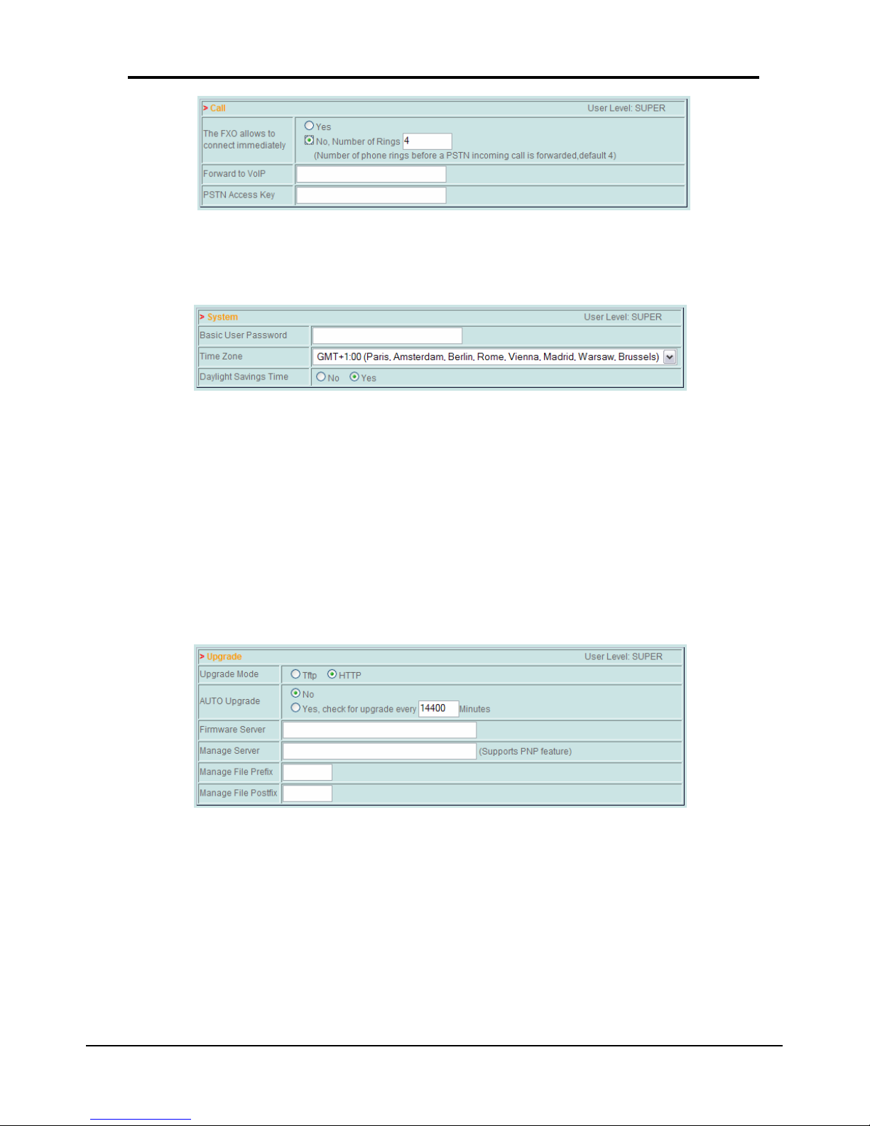
Call
This section includes settings relating to the PSTN analogue line.
With this option you can d
The FXO allows
transferred to the PBX or alternatively re-
to connect
phone. In
immediately
needs to ring before the call is transferred to the PBX.
Forward to VoIP
transferred to.
user, hunt group, IVR node, etc.).
PSTN Access
Key
(FXO line).
15
© VOI
SPEED LTD
.
VOI
SPEED
V-6017
Page 16
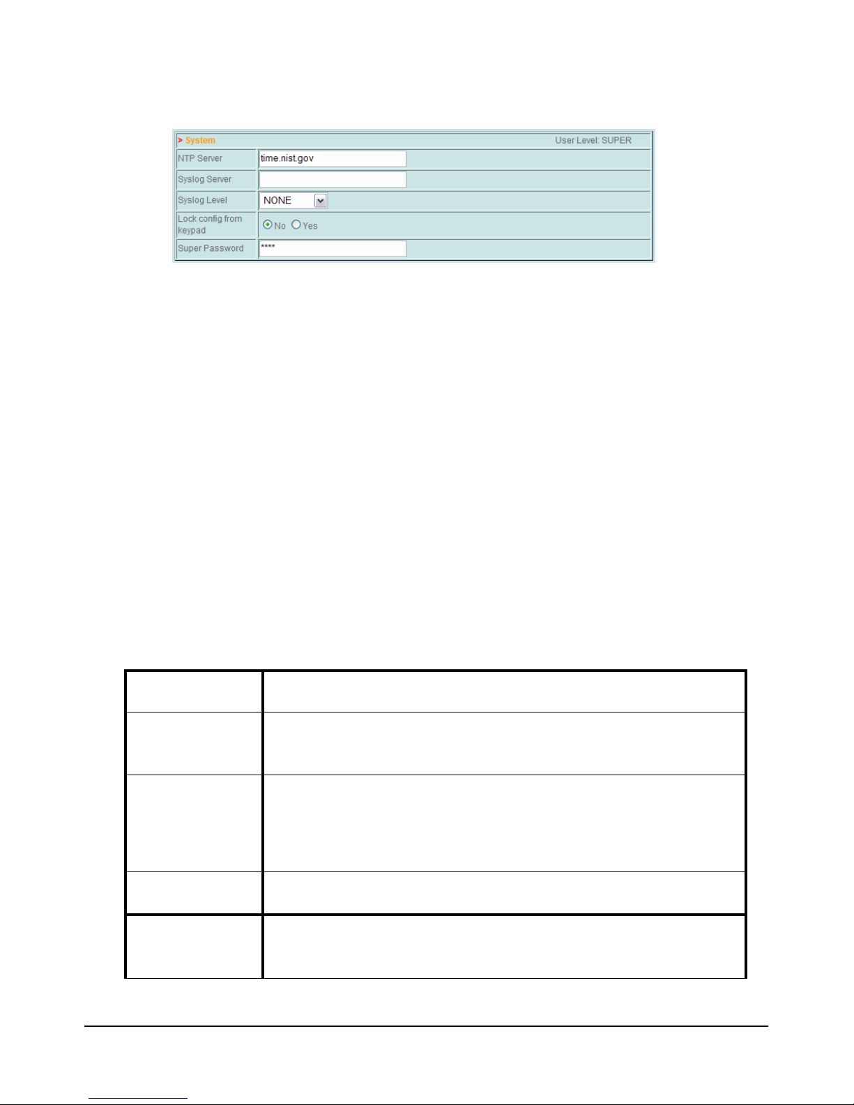
System
In this section you can find system time settings: Time Zone and Daylight Saving Time.
7.4 - Admin Options
This section lists all main functionalities set by the system administrator.
Upgrade
Here you can configure the adpater to automatically update its firmware using a remote
TFTP or HTTP server. You will need to select the updating mode and the server’s name
and IP address (Firmware Server).
By setting the auto-upgrade function the system will automatically check for new firmware
updates at regular intervals (default: 10 days). In ‘Manage Server’ you will need to enter
the server’s name and IP address.
System
In this section you can enter the settings for NTP and Syslog servers. You can also
change the web interface access password and enable or disable the possibility of
entering commands using the emergency phone connected to the FXS port (see section
5 -Getting started for more information).
U
SER MANUAL
© VOI
SPEED LTD
.
16
Page 17
Note: the extension number is used by some PBXs to carry out the
Reset default
Select Reset default in order to restore the manufacturer’s default settings (you will need
to press ‘reset’ to confirm). You can also reset the adapter by using the keypad of the
emergency phone (see section 5 - ).
7.5 - FXO Port
This section enables you to configure the settings of the FXO port connected to the
analogue PSTN line.
Account
In the account section you can setup how the PBX should make phone calls over the
PSTN network. You should select ‘Yes’ for SIP Registration if you want the PBX to
consider the adapter as a normal extension. In this case you should also enter the IP
address of the proxy and the server as well as all relevant details for the authentication
(see table below).
SIP Server Enter name and IP address of the server.
Outbound
Proxy
Here you can enter the Proxy server details if required.
Extension number to give to the adapter.
SIP User ID
registration.
Account ID Username for the extension.
Authentication
Password
17
Password used to authenticate the extension at the PBX.
© VOI
SPEED LTD
.
VOI
SPEED
V-6017
Page 18
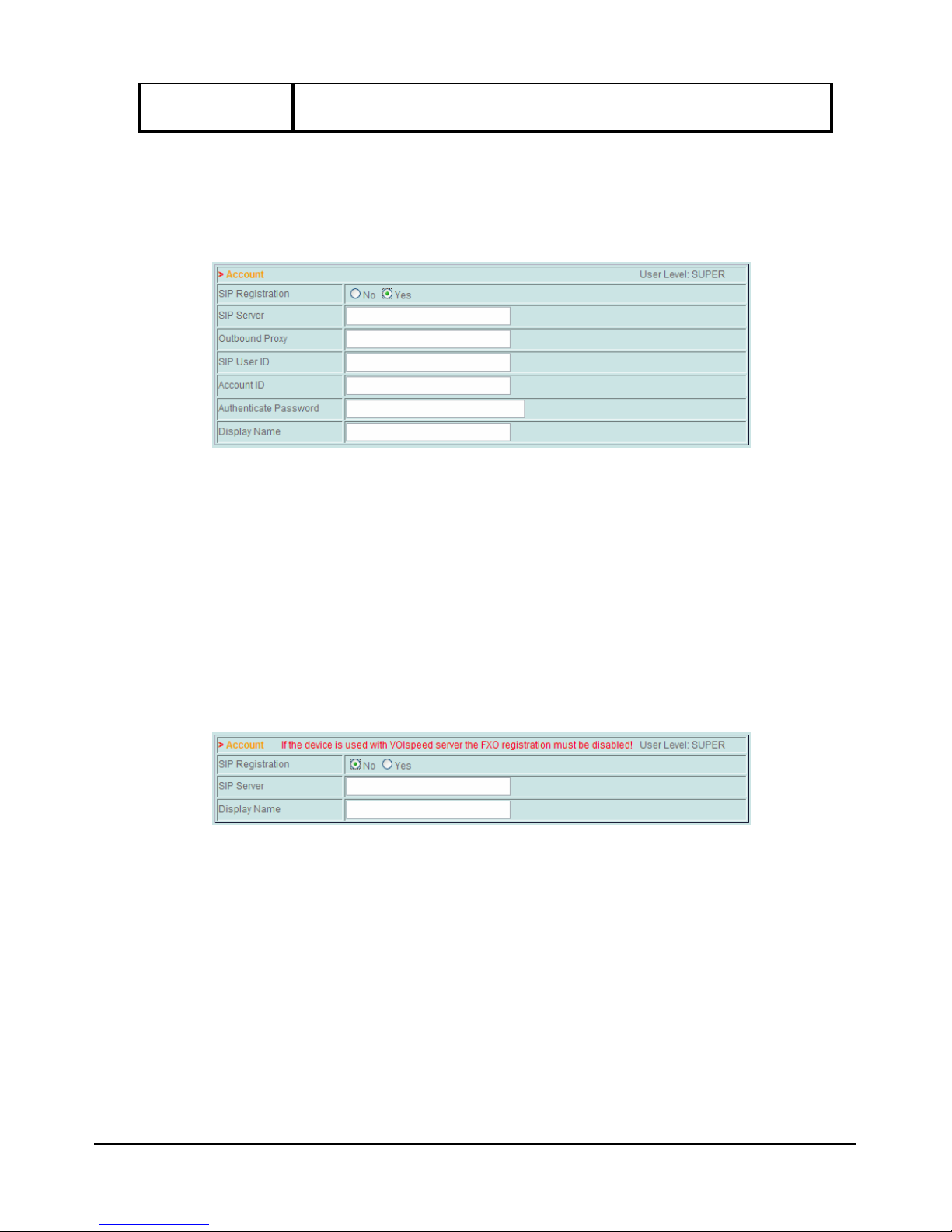
Display Name Name to be used in all outgoing calls.
In case the FXO is registered at the PBX as a traditional extension, the user will need to
dial the extension number first (associated to the FXO) followed by the destination
number in order to make a new phone call over PSTN.
You can alternatively configure the adapter to be considered by the PBX as a traditional
SIP carrier. In this case you should enter ‘No’ in SIP Registration together with the
server IP address. At the VOIspeed server PBX you should create a new SIP carrier
following these criteria:
- The Proxy IP address should be the socket number of the FXO Port: the
adapter’s IP address followed by semicolon (‘:’) and the FXO Port (as
defined in the SIP section). Default value for this port is 5062.
- Realm parameter should be set to ‘voispeed’.
- Select the ‘Always Registered’ option.
- Configure ‘Voice Coding’ and DTMF settings as required.
As before, Display Name field will be used to identify the PBX in all outgoing calls over
the PSTN line.
Note: if you have configured the FXO adapter as a PBX extension, the Caller ID for all
outgoing calls is the extension number associated to the adapter.
SIP
In this section you can define the settings in case the adapter should register itself with
the PBX server.
U
SER MANUAL
© VOI
SPEED LTD
.
18
Page 19
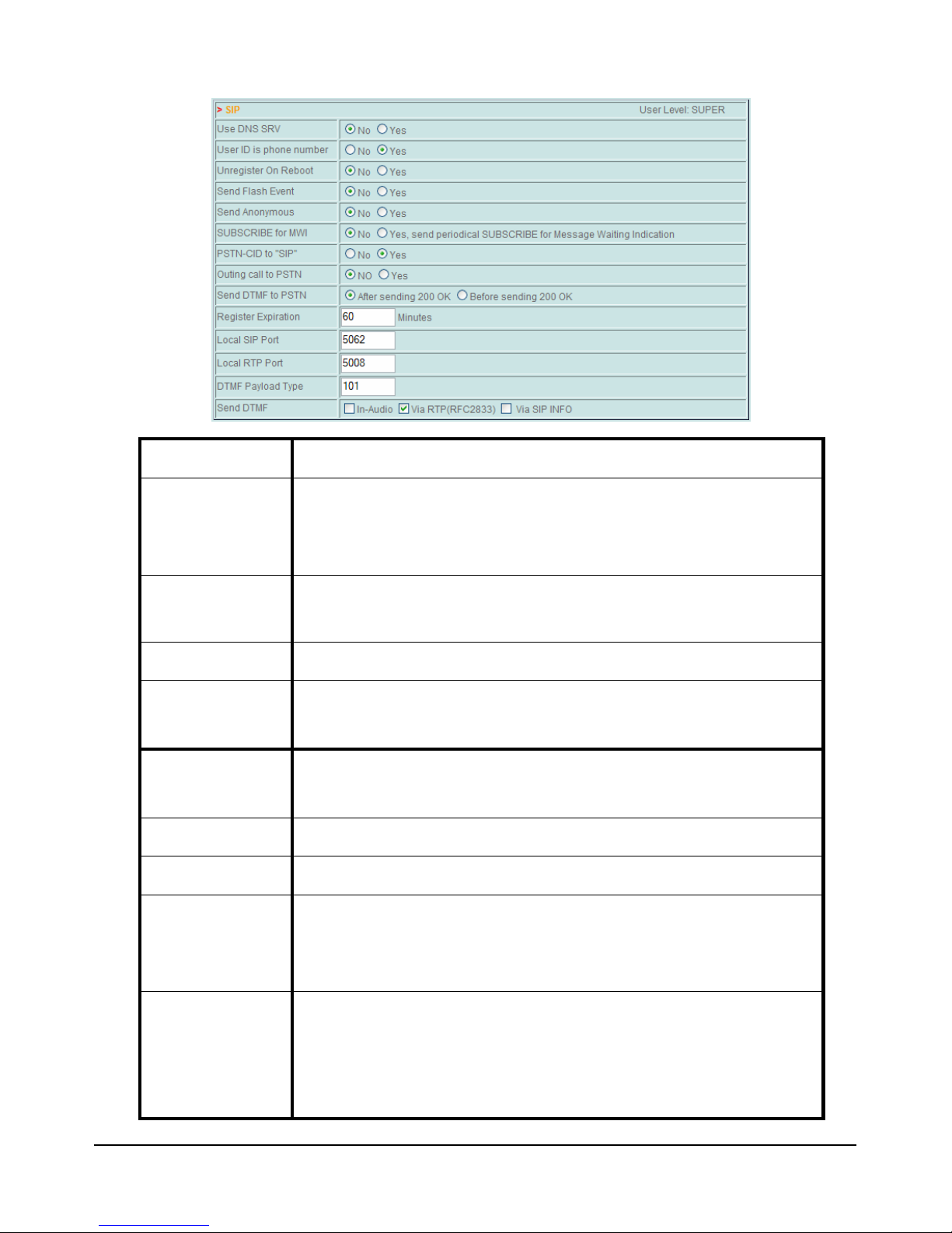
When enabled, the system uses the Account ID (as entered in the
Account section) as the extension number or as User ID for the
When enabled, the adapter sends an ‘Unregister’ message to the
When enabled, the adapter asks the PBX to signal the presence of
The adapter register iself on a regular basis. This setting determines
this parameter needs to be set to 101 when the adapter is
he audio
to send DTMF signals using the RFC 2833
Use DNS SRV Enables the DNS server for domain services.
User ID is phone
number
authentication.
Unregister On
Reboot
PBX before rebooting.
Send Anonymus When enabled, all outbound calls are anonimous.
SUBSCRIBE for
MWI
new voicemail messages.
Register
Expiration
the amount of time elapsing between two registrations.
Local SIP Port Local port used for SIP signalling with the PBX.
Local RTP Port Local port used to exchange voice packets.
Code to be included in the payload of DTMF packets.
DMTF Payload
Note:
Type
used with a VOIspeed PBX.
DTMF settings:
- Select ‘In Audio’ to send DTMF signals within t
Send DTMF
band.
- Select ‘Via RTP’
19
© VOI
SPEED LTD
.
VOI
SPEED
V-6017
Page 20

standard.
to send DTMF signals within SIP INFO
When the PBX begins routing an outgoing call over the PSTN
network, it sends a request signal to the FXO port. This port replies
message in case the outgoing call is allowed to go
the adapter
back to the PBX before sending the
DTMF signals (containing the destination number) over the PSTN
line. In this case you will be able to hear dialling tones on the phone.
is selected, the
adapter sends DTMF signalling before acknowledging the
transmission back to the PBX. This option enables the adapter to
s over the PSTN
he PSTN
- Select ‘Via SIP INFO’
messages (outdated).
The settings below should be considered only if the SIP adapter is being used as a SIP
carrier.
with a ‘200 OK’
ahead. By selecting the option ‘After sending 200 OK’
Send DTMF to
sends the acknowledgment
PSTN
Alternatively, when ‘Before sending 200 OK’
emulate a traditional SIP carrier.
Outing call to
PSTN
PSTN-CID to
"SIP”
When enabled, the PBX can perform outgoing call
line.
When enabled, the adapter detects the Caller ID sent over t
line and communicates it to the PBX server using the SIP standard.
Note: the first two options above should be disabled when the FXO adapter
registers on the PBX as a normal extension.
Note: the adapter requires the phone to ring twice in order to detect the Caller
ID when this information must be sent to the PBX. In such a case, the
emergency phone (when connected to the FXS port) rings twice.
Voice
In this section you can configure the codec settings.
U
SER MANUAL
© VOI
SPEED LTD
.
20
Page 21
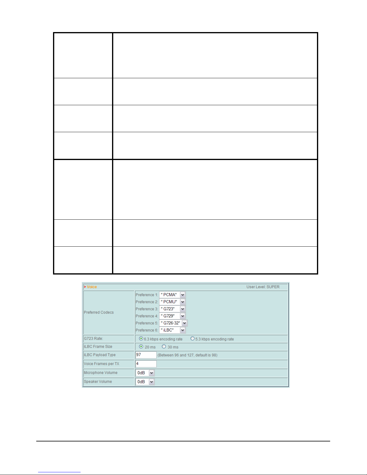
Preferred
Here you can list the audio codecs that the adapter should use
during a conversation. At the beginning of each call, the PBX goes
from
This parameter determines the compression level of the G723
iLBC Frame
iLBC Payload
Voice Frames
Number of frames sent in each audio packet. Each frame contains
Note: this parameter needs to be set to 4 when connecting the
th
Codecs
through this list selecting the best codec (for that call) starting
the one on the top (Preference 1).
G723 Rate
Size
Type
per TX
Microphone
Volume
Speaker
Volume
audio codec.
Determines the size of the iLBC frames.
iLBC Payload: possible values go from 96 to 127 (default: 98).
10 ms of audio signal.
adapter to a VOIspeed PBX. VOIspeed technology operates wi
40 ms audio frames.
Audio level on the analogue line.
Audio level on the PBX line.
PSTN & Dial
Here you can enter advanced settings for the PSTN line.
21
© VOI
SPEED LTD
.
VOI
SPEED
V-6017
Page 22
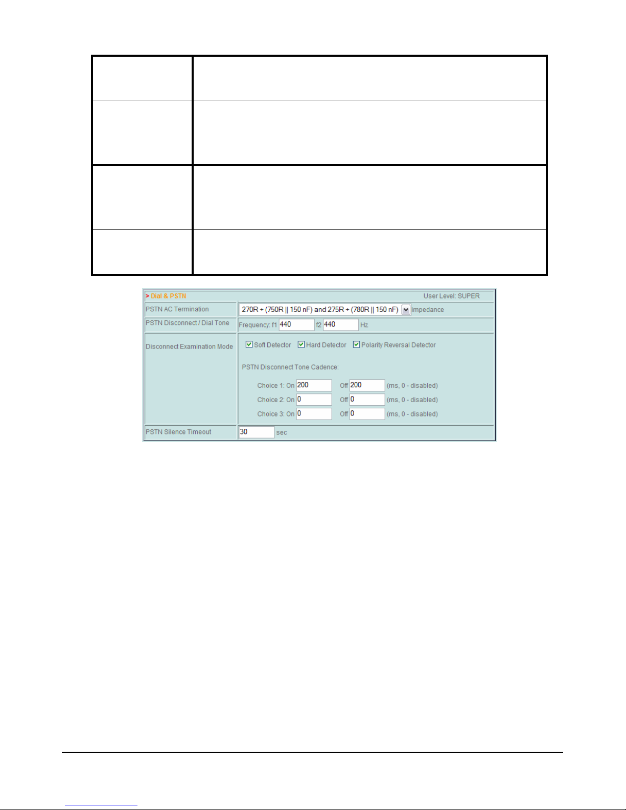
PSTN AC
connected to the FXO
Depending on the Country, audio signals over the PSTN line can be
Here you can configure how the adapter should detect the
These settings should not be
This setting determines the time the adapter should wait before
Determines the impedance on the PSTN line
Termination
PSTN
Disconnect / Dial
Tone
Disconnect
Examination
Mode
PSTN Silence
Timeout
port.
transmitted using either two frequencies (MF) or only one (SF).
Amongst these signals is the Disconnection Tone.
disconnection tone and its duration.
modified unless strictly necessary.
disconnecting the call in case no audio is detected on the line.
U
SER MANUAL
© VOI
SPEED LTD
.
22
 Loading...