

Voipac iMX6 OpenRex SBC Quick Manual
iMX6 OpenRex SBC
QUICK GUIDE

Last updated: June 26, 2017

About Voipac iMX6 OpenRex Single Board Computer (SBC) 4
Packing List 4
Connectors Locations 5
Connecting the Components and Cables 6
The First Steps 7
Controlling iMX6 OpenRex SBC Over Serial Line 7
Using External Monitor and USB Keyboard 8
Controlling iMX6 OpenRex SBC Over Ethernet (telnet, ssh, ftp, sftp) 8
MfgTool for Booting by USB OTG 10
MfgTool 10
SPI Bootloader 13
How to Flash SPI Bootloader (u-boot-imx6-openrex*.imx) 13
Creating Bootable microSD Card 16
USB Writer 16
Important and Usefull Information 19
Products` Life Cycle Phase 19
CE Compliance of Voipac Products 19
TECHNICAL SUPPORT 19
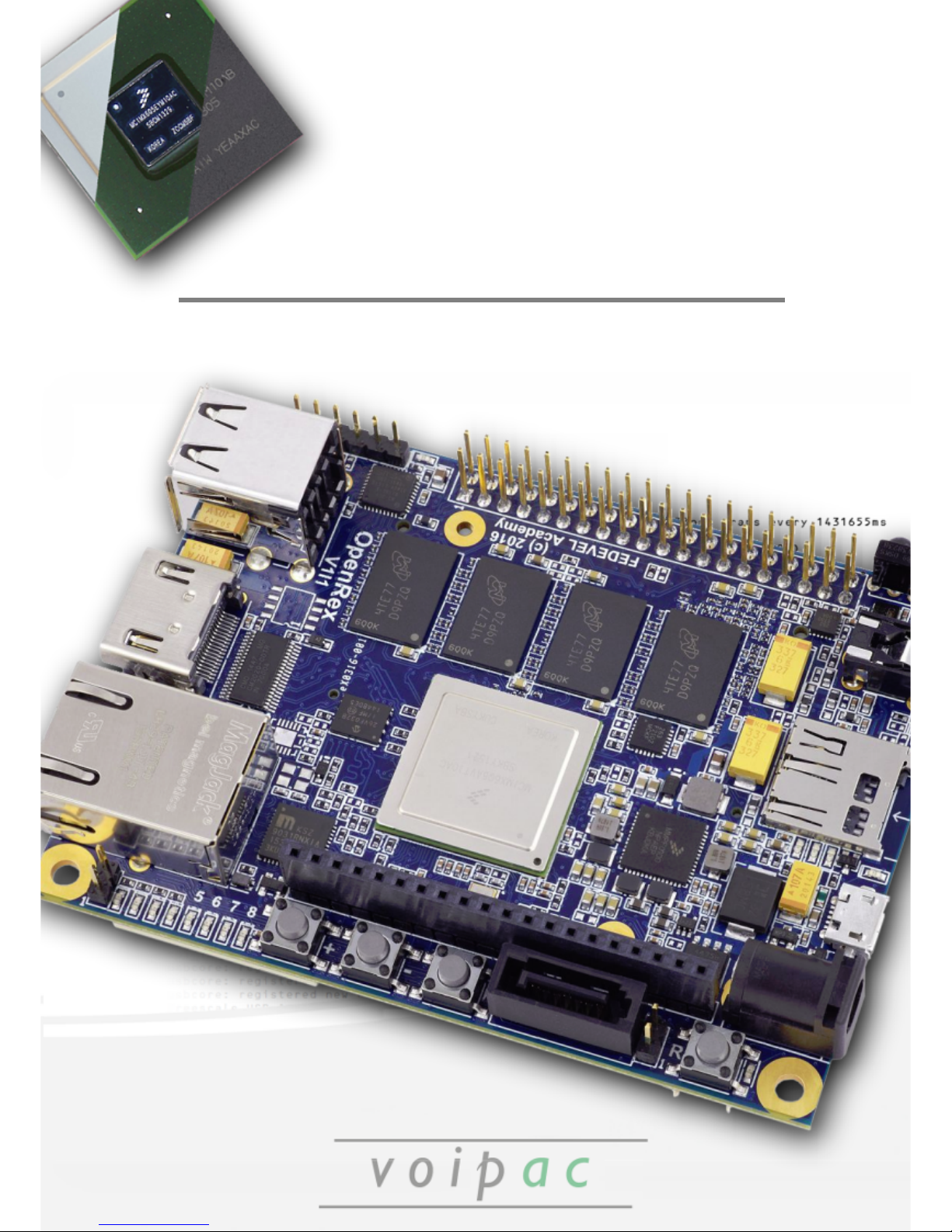
About Voipac iMX6 OpenRex Single Board Computer (SBC)
iMX6 OpenRex Single Board Computer (SBC) a completely open source SBC powered by
NXP/Freescale i.MX6 ARM® Cortex® A9 multicore CPU. The board further features NXP LPC1345
ARM® Cortex® M3 microcontroller, multiple camera inputs, and a series of built-in sensors including
compass & accelerometer, gyroscope, humidity sensor, and temperature sensor making it ideal
choice for industrial as well as home automation applications.
It was designed also for playing, learning and hacking thus includes also Raspberry Pi
& Arduino like GPIO headers.
This Quick Guide shows, how to flash the board using MfgTool program, load Yocto Project
Linux image on microSD card using USB writer. Programs run under Windows XP/7/8/10. More
information available at: imx6 openrex at wiki.voipac.com.
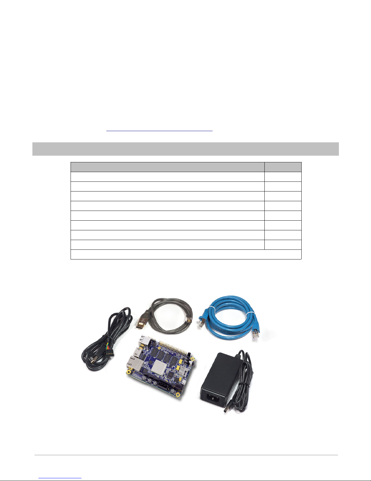
Packing List
COMPONENTS QUANTITY
iMX6 OpenRex Single Board Computer 1
8GB microSDHC Class 4 memory card 1
Aluminum 35 x 35 x 10mm heatsink 1
TTL-232R-3V3 cable (Optional) 1
HDMI High Speed CAT.2 cable with Ethernet (Optional) 1
SFTP CAT.6 Patch Ethernet cable (Optional) 1
5V Power supply (Optional) 1
Quick Guide brochure 1
Yocto Project Linux OS preinstalled. (Android 7.1 preinstalled upon request)
- 4 -
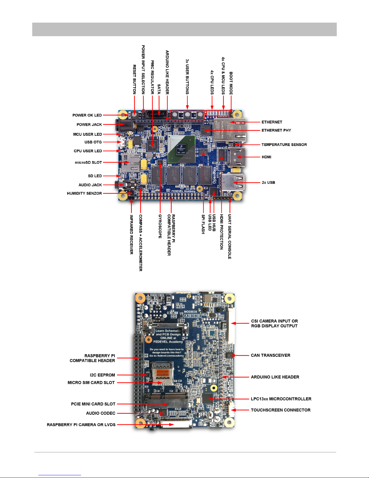
Connectors Locations
- 5 -
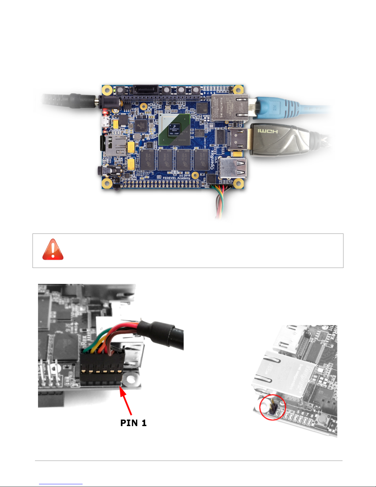
Connecting the components and cables
Prepare iMX6 OpenRex SBC and plug in (bootable) microSD card, TTL-232R-3V3 FTDI cable,
Ethernet cable, HDMI cable and other devices or interfaces you need. Plug the power supply
connector in.
IMPORTANT! Be careful when connecting TTL-232R FTDI cable to the board.
Check if the cable conductor 1 (black wire) is connected to Pin 1 (Header
connector J3 – TTL-232R FTDI) on the board.
To boot from microSD Card, make sure
that BOOT_MODE jumper is not present.
- 6 -
 Loading...