

Page 1
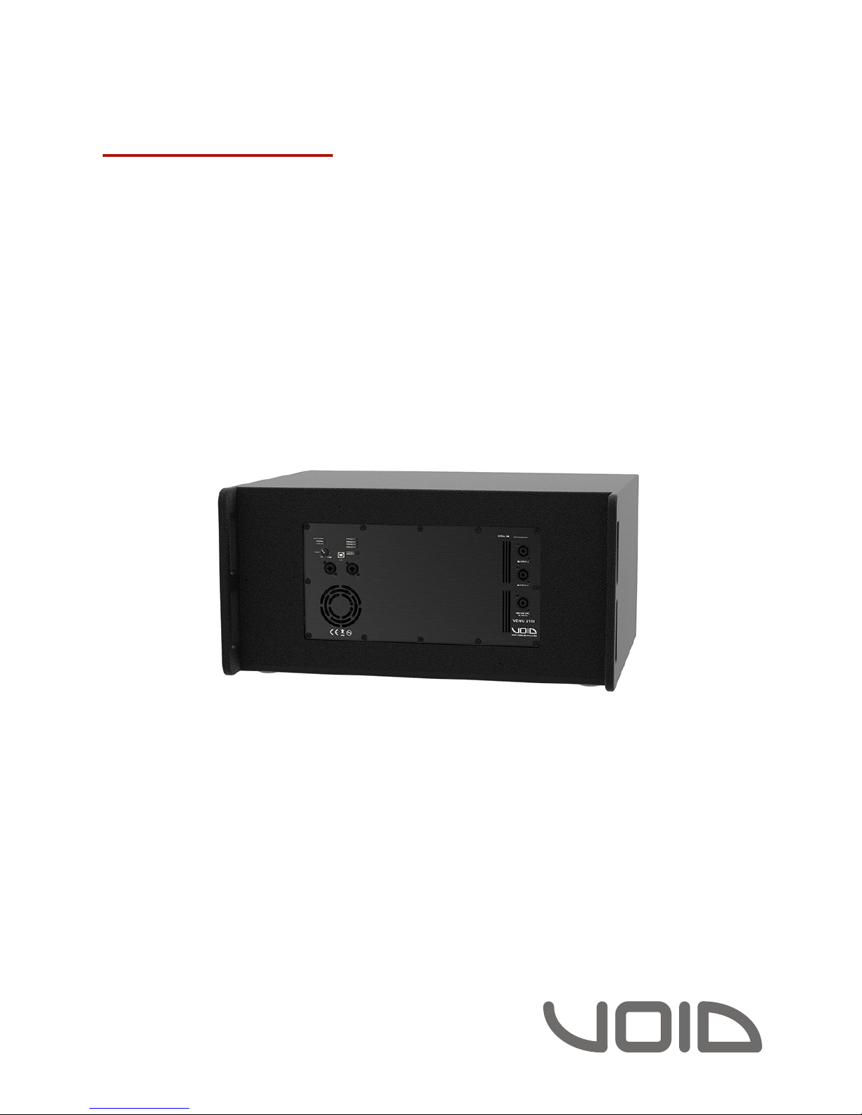
Venu 210i
User Guide V1.0
Page 2

©2018 Void Acoustics Research Ltd.
Version 1.0
This user guide is subject to change without notice.
For the latest online version, visit: www.voidacoustics.com
Void Acoustics and the Void logo are registered trademarks of Void
Acoustics Research Ltd. in the United Kingdom, USA and other
countries; all other Void trademarks are the property of Void Acoustics
Research Ltd.
Page 3

Venu 210i User Guide V1.0
Page 3
Contents
1 Safety and regulations 4
1.1 Important safety instructions 4
1.2 Limitations 4
1.3 EC declaration of conformity 4
1.4 WEEE directive 4
2 Limited warranty 5
3 Unpacking and Checking 6
4 About 7
4.1 Welcome 7
4.2 Venu 210i overview 7
4.3 Key features 7
4.4 Venu 210i specifications 8
4.5 Dimensions 9
5 Cabling and wiring 10
5.1 Electrical safety 10
5.2 Cable considerations for fixed installations 10
5.3 Venu 210i wiring 11
5.4 Input connectors 12
5.5 Output connectors 12
6 Venu 210i DSP 13
6.1 Components 13
6.2 Factory presets 14
6.3 Selecting your presets 14
6.4 LED chart 14
6.5 Software 15
6.6 Processing architecture 16
6.7 Internal signal path polarity 17
7 System design 18
7.1 System design principles 18
7.2 High frequency loudspeaker placement and positioning 19
7.3 Bass alignment - delay times 22
8 Service 23
7.1 Return authorisation 23
7.2 Shipping and packing considerations 23
9 Appendix 24
Page 4
Venu 210i User Guide V1.0
Page 4
1.1 Important safety instructions
The lightning flash with and arrowhead symbol
within an equilateral triangle is intended to alert the
user to the presence of uninsulated “dangerous
voltage” within the product’s enclosure that may
be of sucient magnitude to constitute a risk of
electric shock to persons.
The exclamation point within an equilateral triangle
is intended to alert the user of the presence of
important operating and maintenance (servicing)
instructions in the literature accompanying the
appliance.
Safety instructions - read this first
1. Read these instructions.
2. Keep these instructions.
3. Heed all warnings.
4. Follow all instructions.
5. Do not use this apparatus near water.
6. Clean only with a dry cloth.
7. Do not block any ventilation openings. Install in accordance
with the manufacturer’s instructions.
8. Do not install near any heat source such as radiators, heat
registers, stoves, or other such apparatus that produce heat.
9. Do not defeat the safety purpose of the grounding-type
plug. A grounding type plug has two blades and a third
grounding prong. The third prong is provided for your safety.
If the provided plug does not fit into your outlet, consult an
electrician for replacement of the obsolete outlet.
10. Protect power cords from being walked on or pinched
particularly at plugs, convenience receptacles, and the point
where they exit the apparatus.
11. Onlyuseattachmentsandaccessoriesspecifiedby Void
Acoustics.
12. Only use with the cart, stand, tripod, bracket, or table specified
by the manufacturer, or sold with the apparatus. When a
cart is used, use caution when moving the cart/apparatus
combination to avoid injury from tip-over.
13. Unplugtheapparatusduringlightningstormsorwhenunused
forlongperiodsoftime.
14. Refer all servicing to qualified service personnel. Servicing
is required when the apparatus has been damaged in
any way, such as when the power-supply cord or plug is
damaged, liquid has been spilled or objects have fallen into
the apparatus, the apparatus has been exposed to rain or
moisture, does not operate normally, or has been dropped.
15. Since the mains power supply cord attachment plug is used
to disconnect the device, the plug should always be easily
accessible.
16. Void loudspeakers can produce sound levels capable
of causing permanent hearing damage from prolonged
exposure. The higher the sound level, the less exposure
needed to cause such damage. Avoid prolonged exposure to
the high sound levels from the loudspeaker.
1.2 Limitations
This guide is provided to help familiarise the user with the
loudspeaker system and its accessories. It is not intended to provide
comprehensive electrical, fire, mechanical and noise training and is
not a substitute for industry-approved training. Nor does this guide
absolve the user of their obligation to comply with all relevant
safety legislation and codes of practice.
While every care has been taken in creating this guide, safety is
user-dependent and Void Acoustics Research Ltd cannot guarantee
complete safety whenever the system is rigged and operated.
1.3 EC declaration of conformity
Manufacturer:
Void Acoustics Research Ltd,
Unit 15 Dawkins Road Ind Est,
Poole, Dorset,
BH15 4JY,
United Kingdom.
We declare the under our sole responsibility the following product
models: Venu 6, 8, 10, 12, sub, bass, X, 115, 215, 210i
are intended to be used as loudspeakers and are in conformity with
the following EC Directives, including all amendments, and with
national legislation implementing these directives and standards:
• 2006/95/EC Low Voltage Directive
• 2004/108/EC Electromagnetic Compatibility Directive
• 2002/95/CE RoHs Directive
• BS EN 60065:2002
• BS EN 55103-1/-2
• BS EN 61000-3-2
• BS EN 61000-3-3
• BS EN 61000-4-2
• BS EN 61000-4-3
• BS EN 61000-4-4
• BS EN 61000-4-5
• BS EN 61000-4-6
• BS EN 61000-4-11
Alex Skan
Technical Director
1.4 WEEE directive
If the time arises to throw away your product, please recycle all the
components possible.
This symbol indicates that when the end-user
wishes to discard this product, it must be sent
to separate collection facilities for recovery
and recycling. By separating this product from
other household-type waste, the volume of
waste sent to incinerators or land-fills will be
reduced and natural resources will thus be
conserved.
The Waste Electrical and Electronic Equipment Directive (WEEE
Directive) aims to minimise the impact of electrical and electronic
goods on the environment. Void Acoustics Research Ltd complies
with the Directive 2002/96/EC and 2003/108/EC of the European
Parliament on waste electrical finance the cost of treatment and
recovery of electronic equipment (WEEE) in order to reduce the
amount of WEEE that is being disposed of in land-fill sites. All of
our products are marked with the WEEE symbol; this indicates that
this product must NOT be disposed of with other waste. Instead
it is the user’s responsibility to dispose of their waste electrical
and electronic equipment by handing it over to an approved
reprocessor, or by returning it to Void Acoustics Research Ltd for
reprocessing. For more information about where you can send
your waste equipment for recycling, please contact Void Acoustics
Research Ltd or one of your local distributors.
1 Safety and regulations
Page 5

Venu 210i User Guide V1.0
Page 5
The warranty
For a period of three (3) years from the date of
delivery to the original purchaser (as shown on the
original invoice or sales receipt; a copy of this may be
required as proof of warranty dates), Void Acoustics
Research Ltd (hereinafter ‘Void’) warrants to the
Original Owner (person or company who originally
purchased the product brand new from either Void
or a Void Authorised Dealer/Distributor) of each new
Venu Series product (provided it was purchased at
an Authorised Void Dealer) that it is free of defects
in materials and workmanship and that each
product will meet or exceed all factory published
specifications for each respective model. Void agrees
to repair or replace (at its discretion) all defective
parts at no charge for labour or materials; subject to
following provisions:
Warranty violations
Void shall take no responsibility for repair or
replacement as specified under this warranty, if
the damaged product has been subject to misuse,
accident, neglect or failure to comply with normal
maintenance procedures; or if the serial number
has been defaced, altered or removed. Nor will Void
accept responsibility for, or resulting from, improper
alterations or unauthorised parts or repairs. This
warranty does not cover any damage to speakers
or any other consequential damage resulting from
breach of any written or implied warranty.
Void warranty provisions
Void will remedy any defect, regardless of the
reason for failure (except as excluded) by repair, or
replacement. Void will remedy the defect and ship
the product within a reasonable time after receipt of
the defective product at a Void Authorised Service Centre.
To obtain warranty service
If a Void product requires service, the Owner must
contact Void or an Authorised Void Service Centre to
receive an R.A.N. (Return Authorisation Number) and
instructions on how to return the product to the Void
Authorised Service Centre, or to Void.
Void (or its Authorised Service Centre) will initiate
corrective repairs upon receipt of the returned
product. Please save the original carton and all the
packing materials in case shipping is required. All
products being returned to the factory or service
centre for repairs must be shipped prepaid.
If the repairs made by Void or the Void Authorised
Service Centre are not satisfactory, the Owner
is instructed to give written notice to Void. If the
defect or malfunction remains after a reasonable
number of attempts by Void to remedy the defect
or malfunction, the Original Owner shall then have
the option to elect either a refund or replacement of
said Void product free of charge. The refund shall be
an amount equal to but not greater than the actual
purchase price, not including any taxes, interest,
insurance, closing costs and other finance charges
(minus reasonable depreciation on the product).
If a refund is necessary, the Original Owner must
make the defective or malfunctioning product
available to Void free and clear of all liens or other
restrictions.
Equipment modifications
Technical and design specifications are subject to
change without notice.
Void reserves the right to modify or change
equipment (in whole or part) at any time prior to
delivery thereof, in order to include therein electrical
or mechanical improvements deemed appropriate
by Void, but without incurring any liability to modify
or change any equipment previously delivered, or
to supply new equipment in accordance with any
earlier specifications.
Disclaimer of consequential and incidental
damages
You, the Original Owner, are not entitled to recover
from Void any incidental damages resulting from any
defect in the Void product.
This includes any damage to another product or
products resulting from such a defect.
Warranty alterations
No person has the authority to enlarge, amend, or
modify this Warranty. This Warranty is not extended
by the length of time which the Original Owner
is deprived of the use of product. Repairs and
replacement parts provided pursuant to the Warranty
shall carry only the non-expired portion of the
Warranty.
This Statement of Warranty supersedes all
others contained in this user guide.
2 Limited warranty
Page 6

Venu 210i User Guide V1.0
Page 6
All Void Acoustics products are carefully manufactured and thoroughly tested before being
dispatched. Your dealer will ensure that your Void products are in pristine condition before
being forwarded to you but mistakes and accidents can happen.
Before signing for your delivery:
• Inspect your shipment for any signs of contamination, abuse or transit damage as soon as
you receive it
• Check your Void Acoustics delivery fully against your order
• If your shipment is incomplete or any of its contents are found to be damaged; inform the
shipping company and inform your dealer.
When you are removing your Venu 210i loudspeaker from its original packaging:
• Venu 210i loudspeakers come double boxed and each box is stapled shut; take care when
unboxing and removing the staples to avoid injury or damage to the loudspeaker
• If you need to place the Venu loudspeaker on a flat surface ensure you use a lint free
product to protect the finish
• When you have removed the Venu 210i loudspeaker from the packaging inspect it to
ensure there is no damage and keep all original packaging in case it needs to be returned
for any reason.
See section 2 for warranty conditions and see section 7 if your product needs servicing.
3 Unpacking and checking
Page 7

Venu 210i User Guide V1.0
Page 7
4 About
4.1 Welcome
Many thanks for purchasing this Void Acoustics Venu 210i loudspeaker. We truly appreciate
your support. At Void, we design, manufacture and distribute advanced professional audio
systems for the installed and live sound market sectors. Like all Void products, our highly
skilled and experienced engineers have successfully combined pioneering technologies with
groundbreaking design aesthetics, to bring you superior sound quality and visual innovation. In
buying this product, you are now part of the Void family and we hope using it brings you years
of satisfaction. This guide will help you both use this product safely and ensure it performs to
its full capability.
4.2 Venu 210i overview
The Venu 210i is a 2,400 W (1,200 W + 2 x 600 W), self-powered double 10” reflex-loaded low
frequency enclosure, capable of powering up to four loudspeaker enclosures from its built-in,
dual-channel 600 Watt power module. speakON™ sockets are provided for ultra-quick and
reliable connections and a protected rear connector panel allows the enclosure to be placed
against a rear wall without damaging the audio or power connections.
The 210i also features DSP for loudspeaker control and advanced signal processing
capabilities, all of which can be accessed by the rear USB port. Add to this the evocative Void
sound from the new range of custom designed components and it’s clear that Venu is the
ultimate installation series.
4.3 Key features
• 2,400 W RMS (1,200 W + 2 x 600 W)
• Capable of powering up to four mid high enclosures
• 2 x 10” low frequency drivers
• Built-in DSP
• Textured polyurea finish, optional custom colours
• Weather-resistant perforated steel grille
Page 8

Venu 210i User Guide V1.0
Page 8
4.4 Venu 210i specifications
Bass frequency range 40 Hz - 150 Hz ± 3 dB
Input 2 x 10 kΩ balanced
Dispersion @-6 dB points Omnidirectional
Maximum output 124 dB cont, 130 dB peak
Driver configuration 2 x 10” LF
Height 334 mm (13.1”)
Width 676 mm (26.6”)
Depth 530 mm (21.1”)
Weight 32 kg (70.5 lbs)
Enclosure 15 mm birch plywood
Finish Textured polyurea
Grille Powder-coated perforated steel - foam filter
Output 2 x Neutrik speakON™
2-channel output mode
4 Ω / Ch (balanced) 600 W
8 Ω / Ch (balanced) 400 W
Max output voltage 85 V
peak
Max output current 31 A
peak
Nominal power requirement AC 100 V - 240 V, 50/60 Hz with PFC
Power factor cos φ = 0.9 @ 360 W
Consumption
Standby 0.5 W
Idle 13.5 W
1/8 of max output power @ 8 Ω 220 W
Amplifier and DSP features
DSP Analogue Devices SigmaDSP™
S/N Ratio 115 dB
Crosstalk separation 85 dB @ 1kHz
Input sensitivity 3 V
RMS
/ 11.7 dBu
Input impedance 10 kΩ balanced
THD+N / DIM100 < 0.08% from 0.1 W to full power (typically <0.05%)
Slew rate 50 V/µs @ 8 Ω, input filter bypassed
Damping factor @ 8 Ω <10000 @ 100 Hz
Delay 340 ms input delay, 10 ms per channel output delay
Input equalizer 5 parametric equalizers: hi/lo-shelving, all-pass, band-pass, band-stop, hi/
lo-stop
Output equalizer Parametric IIR filters: peaking, hi/lo-shelving, all-pass, band-pass, band-stop,
hi/lo-pass
Crossover Butterworth, Linkwitz-Riley, Bessel: 6 dB/oct to 48 dB/oct (IIR)
Limiters Peak limiter, RMS limiter, frequency dependent RMS limiter, Clip limiter,
Temperature limiter
4 About
Page 9
Venu 210i User Guide V1.0
Page 9
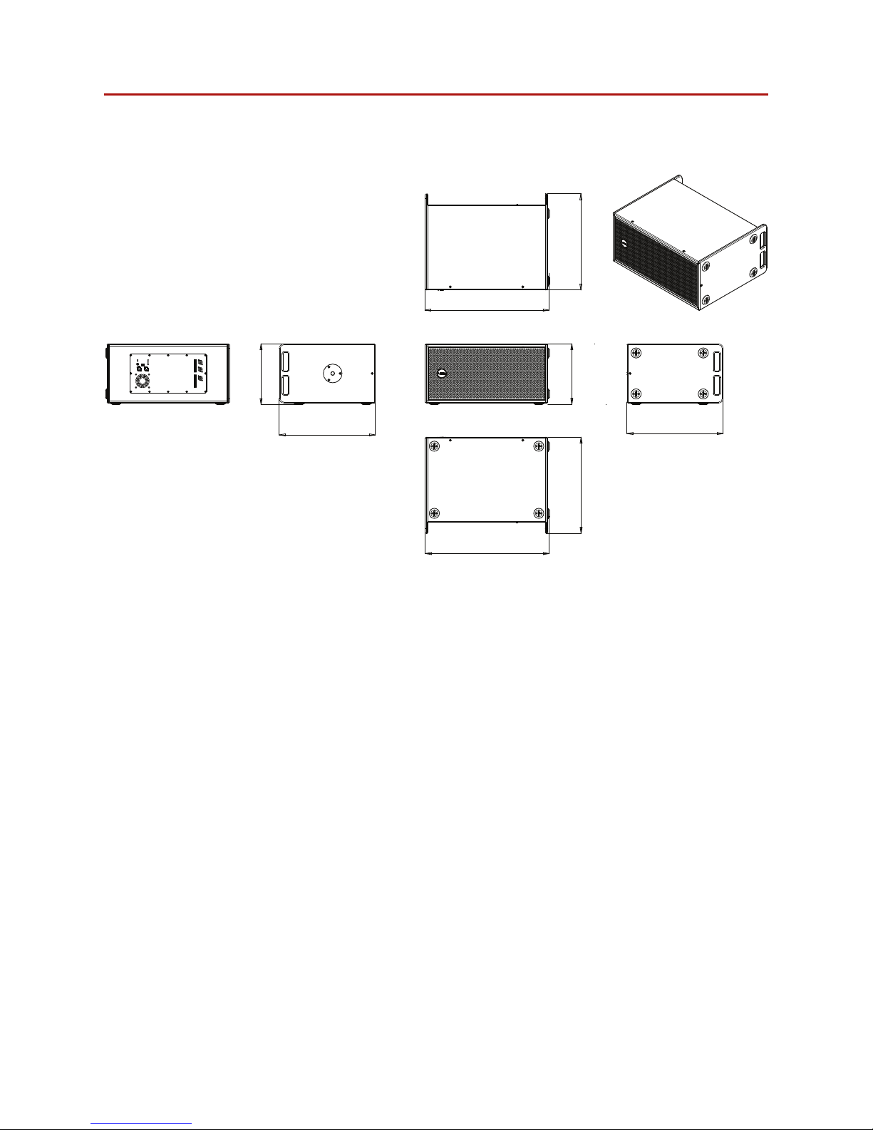
4.5 Dimensions
334 (13.2”)
530 (20.9”)
684 (26.9”)
530 (20.9”)
334 (13.2”)
684 (26.9”)
530 (20.9”)
530 (20.9”)
Figure 4.1: Dimensions
4 About
Page 10

Venu 210i User Guide V1.0
Page 10
5 Cabling and wiring
5.1 Electrical safety
To avoid electrical hazards please note the following:
• Do not access the inside of any electrical equipment. Refer servicing to
Void-approved service agents.
5.2 Cable considerations for fixed installations
We recommend specifying installation-grade Low Smoke Zero Halogen (LSZH) cables for
permanent installations. The cables should use Oxygen Free Copper (OFC) of grade C11000
or above. Cables for permanent installations should be compliant with the following standards:
• IEC 60332.1 Fire retardancy of a single cable
• IEC 60332.3C Fire retardancy of bunched cables
• IEC 60754.1 Amount of Halogen Gas Emissions
• IEC 60754.2 Degree of acidity of released gases
• IEC 61034.2 Measurement of smoke density.
Page 11
Venu 210i User Guide V1.0
Page 11
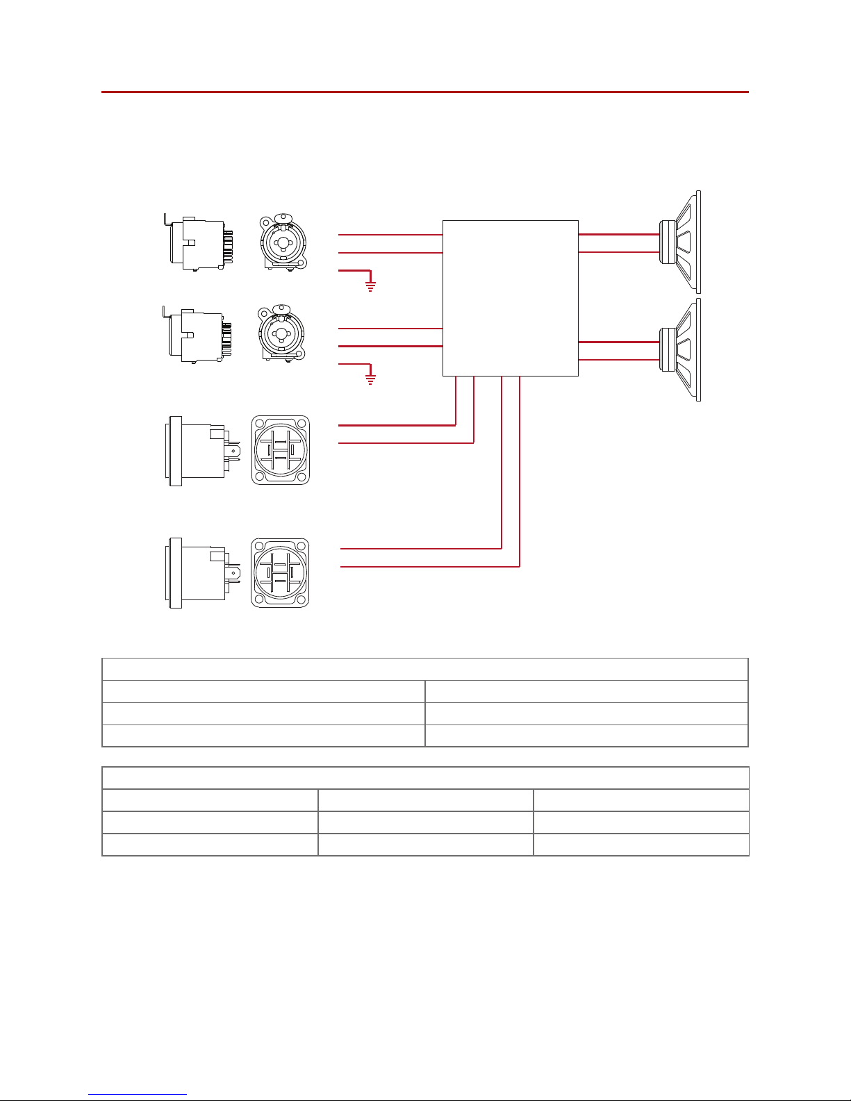
5.3 Venu 210i wiring
+
-
1+
1-
2+
2-
1+
1-
2+
2-
1+
12+
2-
1+
12+
2-
DSP and amplifier
Input A
Out/Link B
10” LF
+
GND
+
GND
Input B
Out/Link A
+
-
10” LF
231
231
Figure 5.1: Venu 210i wiring diagram
Input
XLR pins +/Input A 2 x 10” LF
Input B 2 x 10” LF
Output
speakONTM pins 1+/1- speakONTM pins 2+/2Link/out A Link n/c
Link/out B Link n/c
5 Cabling and wiring
Page 12
Venu 210i User Guide V1.0
Page 12
5 Cabling and wiring
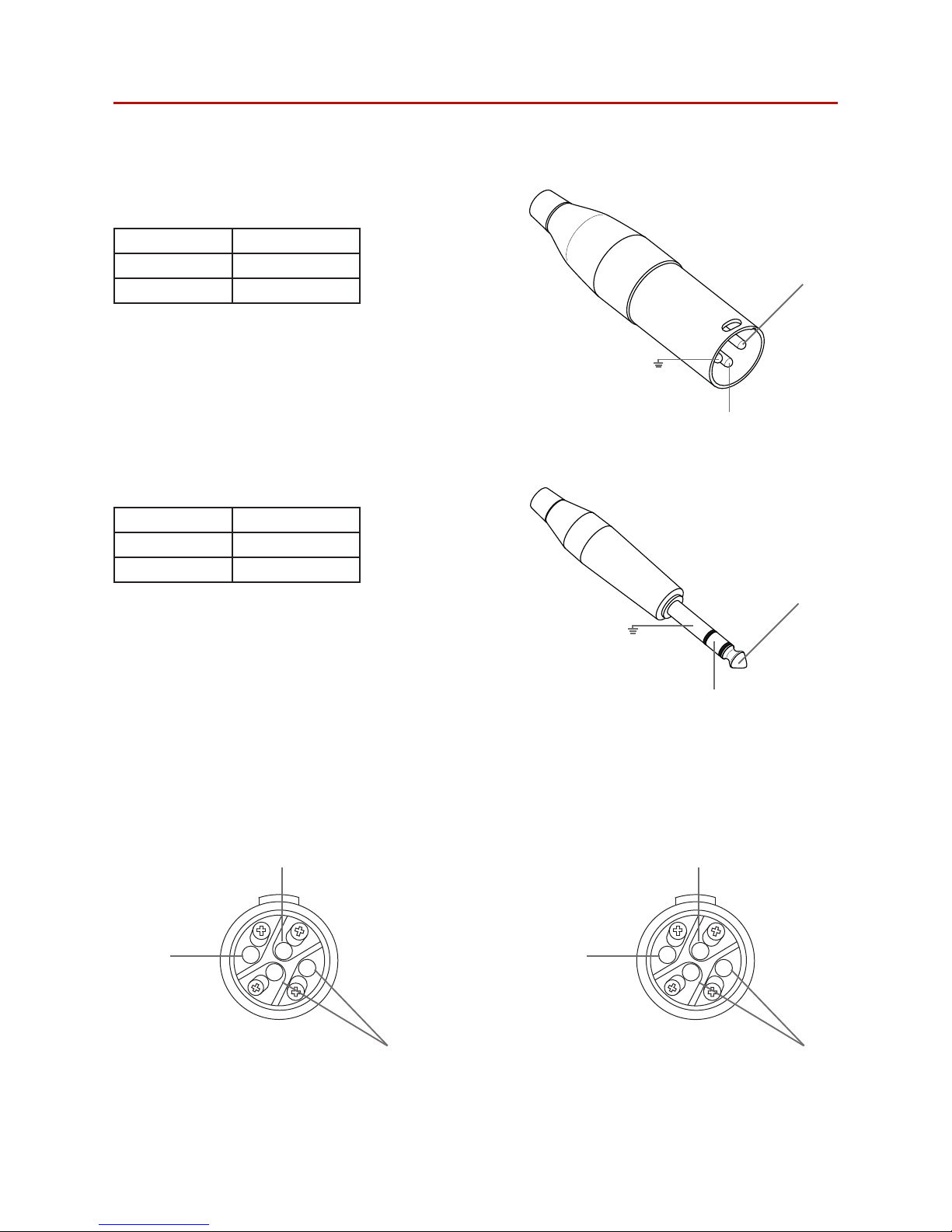
Analogue input XLR-M pinout
Pin 1 GND
Pin 2 Hot +
Pin 3 Cold -
Analogue input TRS Jack pinout
Tip Hot +
Ring Cold Sleeve GND
GND
+Hot
-Cold
GND
-Cold
+Hot
3
2
1
Analogue line output Neutrik speakON™
N/C
CH1+
CH1-
Output A
speakON™
connector
Figure 5.4:Channel 1 and 2 speakON™ connector diagram. Note: pins 2+/2- are not connected.
5.4 Input connectors
5.5 Output connectors
1+
1-
2-
2+
Output B
speakON™
connector
N/C
CH1+
CH1-
1+
1-
2-
2+
Figure 5.2: XLR-M diagram
Figure 5.3: TRS Jack diagram
Page 13
Venu 210i User Guide V1.0
Page 13
6 Venu 210i DSP
CLIP/TEMP
SIGNAL
STATUS
PRESET 1
PRESET 2
PRESET 3
PRESET 4
PRESET
SELECT
∞
+6dB
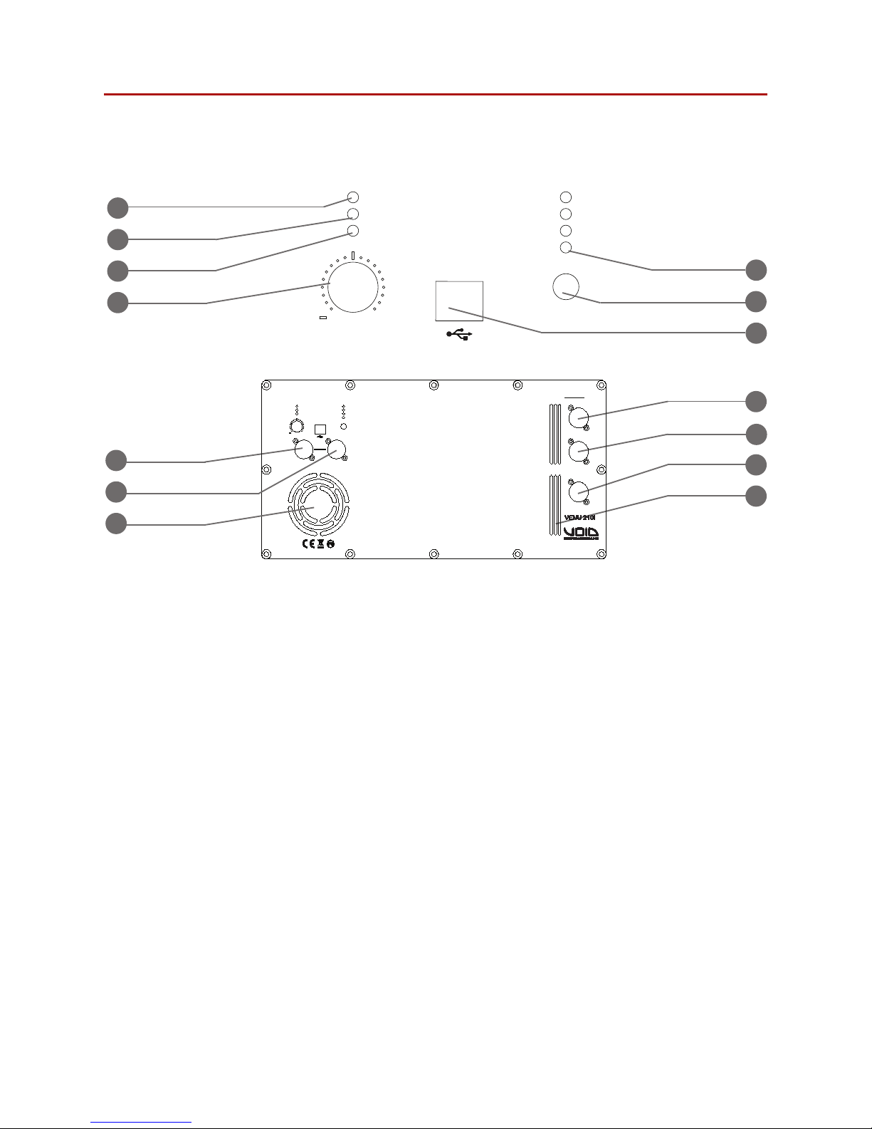
6.1 Components
1
3
2
4
5
6
7
Figure 6.1: LED panel
11
8
12
13
14
1. Signal clipping
2. Signal presence/limiting LED
3. Status LED
4. Volume potentiometer
5. Preset LEDs
6. Preset select
7. USB-B programming connector
8. Combi Jack - XLR input signal connector
input A
9. Combi Jack - XLR input signal connector
input B
10. Fan Inlet
11. Neutrik speakON™ output A
12. Neutrik speakON™ output B
13. PowerCon™ power input
14. Exhaust vents
CLIP/TEMP
SIGNAL
STATUS
PRESET 1
PRESET 2
PRESET 3
PRESET 4
GAIN
∞
+6dB
PRESET
SELECT
INPUT A
INPUT B
SERIAL NO.
OUTPUT A
OUTPUT B
100-240 VAC
50-60 Hz
9
10
Figure 6.2: Rear panel
Page 14

Venu 210i User Guide V1.0
Page 14
6.4 LED chart
Clip/temp LED
Colour Solid on Action required
O Temperature OK, no clipping No action required
Yellow High amplifier temperature Reduce system gain
Red Output signal clipping Reduce system gain
Signal LED
Colour Solid on Action required
Green Input signal present, output not in limit No action required
Yellow Output limiter engaging Reduce system gain
Red Input signal clipping Reduce input gain
Status LED
Colour Solid ON
O System o
Green System ready to play
6.2 Factory presets
Factory presets for the Venu 210i are as follows:
Preset 1 Air 8
Preset 2 Cyclone 55
Preset 3 Indigo 6S
Preset 4 Venu 6
6.3 Selecting your preset
To change your Venu 210i preset:
1. Apply power to the amplifier
2. Wait 15 seconds for the amplifier to initialize
3. Press the preset button
4. The next selected preset light will begin flashing
5. When the preset LED stops flashing and becomes steady the amplifier is ready to use in
that preset mode.
For alternative compatible loudspeaker presets please contact your Void representative.
6 Venu 210i DSP
Page 15
Venu 210i User Guide V1.0
Page 15
6.5 Software
Starting from version 2.11.1, Armonía Pro Audio Suite supports the Venu 210i processing board
which is available from:
http://www.voidacoustics.com/void_uploads/Armonia.zip
In order to access the DSP via the USB port of your computer, the CP210x USB to UART Bridge
Virtual COM Port (VCP) drivers are required.
Freely download the drivers from the Silicon Labs website: www.silabs.com > Products > USB
bridge > Software download > CP210x VCP Drivers:
https://www.silabs.com/products/mcu/Pages/USBtoUARTBridgeVCPDrivers.aspx
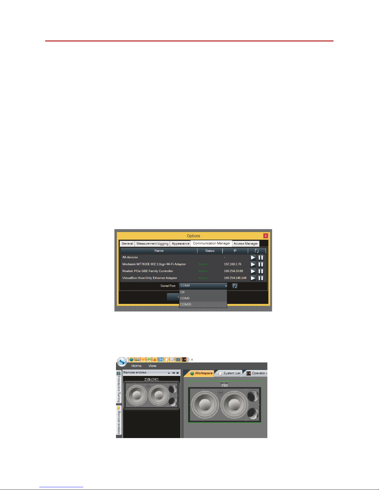
1. Once the driver has been properly installed, the Windows operating system provides a new
virtual COM port with a high identification number.
2. Open Armonía Pro Audio Suite and click on the Armonía button in the top left corner of
the window.
3. Click on the Option button and select the Communication Manager tab.
Figure 6.3: Armonia Pro Audio suite communications manager
4. Activate the Serial Port communication and select the proper COM port (usually the one
with the higher ID).
5. Apply the changes: now Armonía is capable to discover the attached device.
Figure 6.4: Unit embedding DSP-L discovered
6 Venu 210i DSP
Page 16
Venu 210i User Guide V1.0
Page 16
INPUT
DELAY
170ms
INPUT
DELAY
170ms
Input
Processing
Input
Processing
MONO
MIX
Output
Processing
CLIP
LIMITER
Output
Processing
CLIP
LIMITER
Output
Processing
CLIP
LIMITER
VCA
VCA
Input 1
Input 2
Output 1
Output 2
Output 3
Output 4
Vcc clipping
Temperature
POTENTIOMETER
GAIN
EQ
(5 bands)
GAIN
EQ/OVER
(8-11 bands)
OUTPUT
DELAY
10ms
RMS
LIMITER
PEAK
LIMITER
Input processing
Output processing
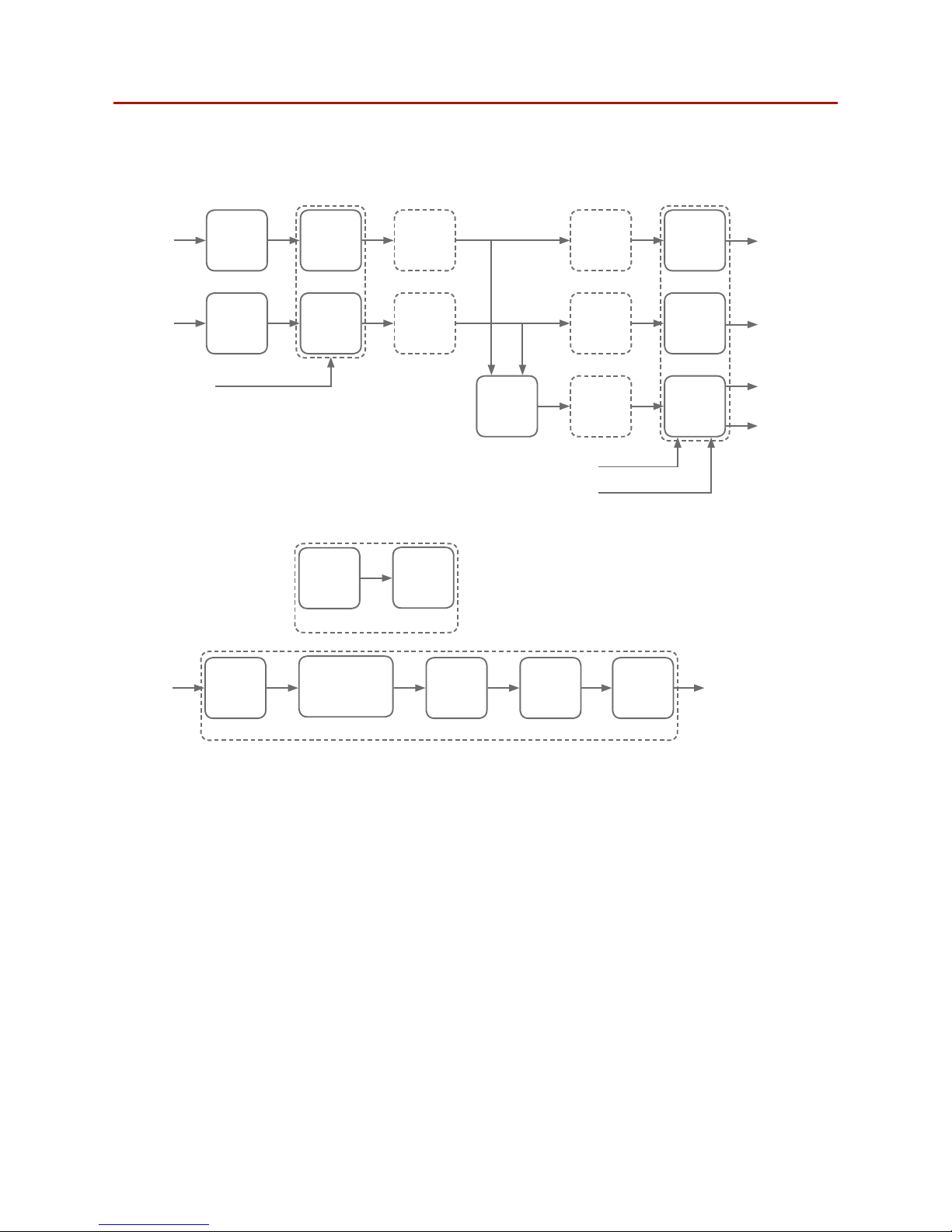
6.6 Processing architecture
6 Venu 210i DSP
Page 17
Venu 210i User Guide V1.0
Page 17
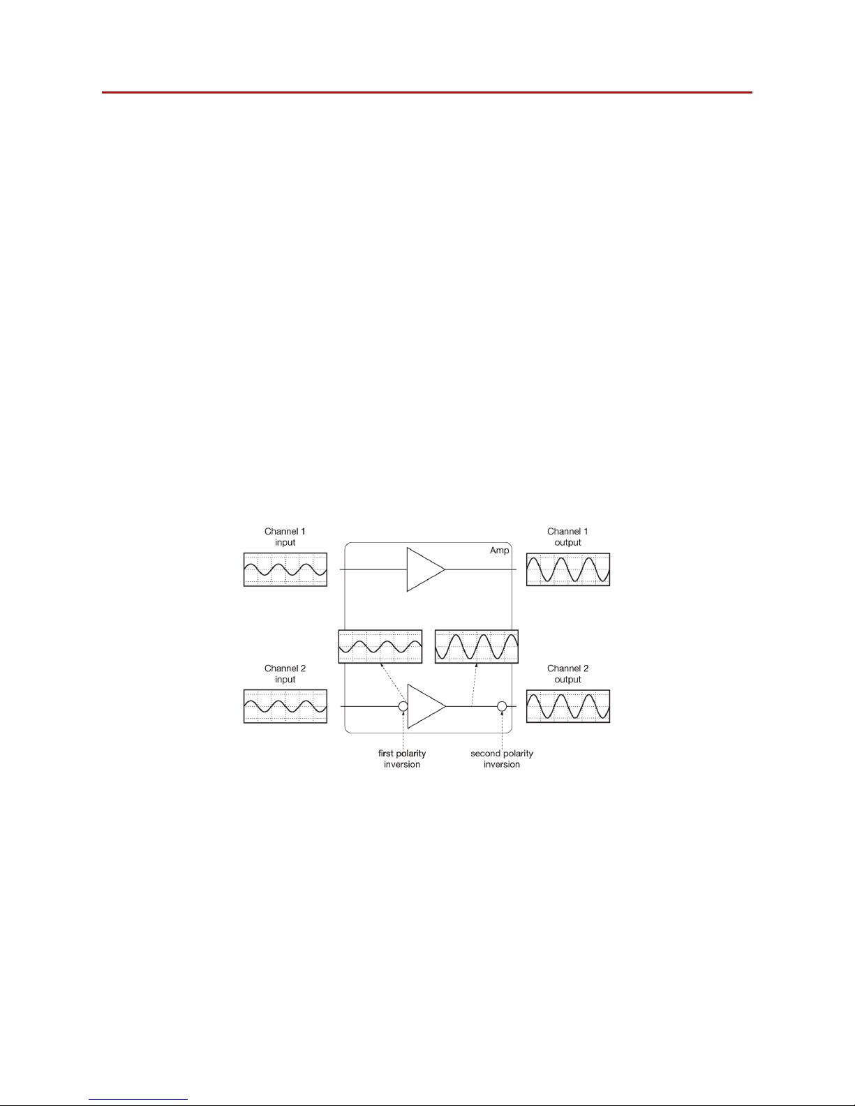
6.7 Internal signal path polarity
In order to increase the power’s supply energy storage eciency, signals coming from
channel pairs 1-2 are polarity reversed, one with respect to the other within the pair, when
entering the amplifier. This ensures a symmetrical use of the voltage rails: if, for example,
both channels’ 1 and 2 input signals are going through a peak at the same time, channel 1’s
energy will come from the positive voltage rails while channel 2, whose polarity is reversed
with respect to channel 1, will be fed energy from the negative voltage rails. In this manner,
the power supply will work symmetrically, with one channel catered by the positive rails and
the other by the symmetrical negative rails. Channel 2’s signal will be polarity reversed once
more to ensure that both channels output with the same polarity as their corresponding
input signals.
For this reason it is very important not to invert the polarity of either channels before feeding
them to the module. A double polarity inversion (the first by the user inserting the input signal
and the other by the amplifier’s internal circuitry) results in no inversion at all. If this were the
case, both channels would be weighing on only one side (positive or negative) of the power
supply’s voltage rails. This would result in an inecient use of the power supply’s energy.
Please pay special attention in using balanced inputs on all measurement equipment (such as
oscilloscope probes) when you are bench testing.
Figure 6.5: Internal signal path polarity with example input signal.
Both channels 1 and 2 are fed with the sma sine signal.
6 Venu 210i DSP
Page 18
Venu 210i User Guide V1.0
Page 18
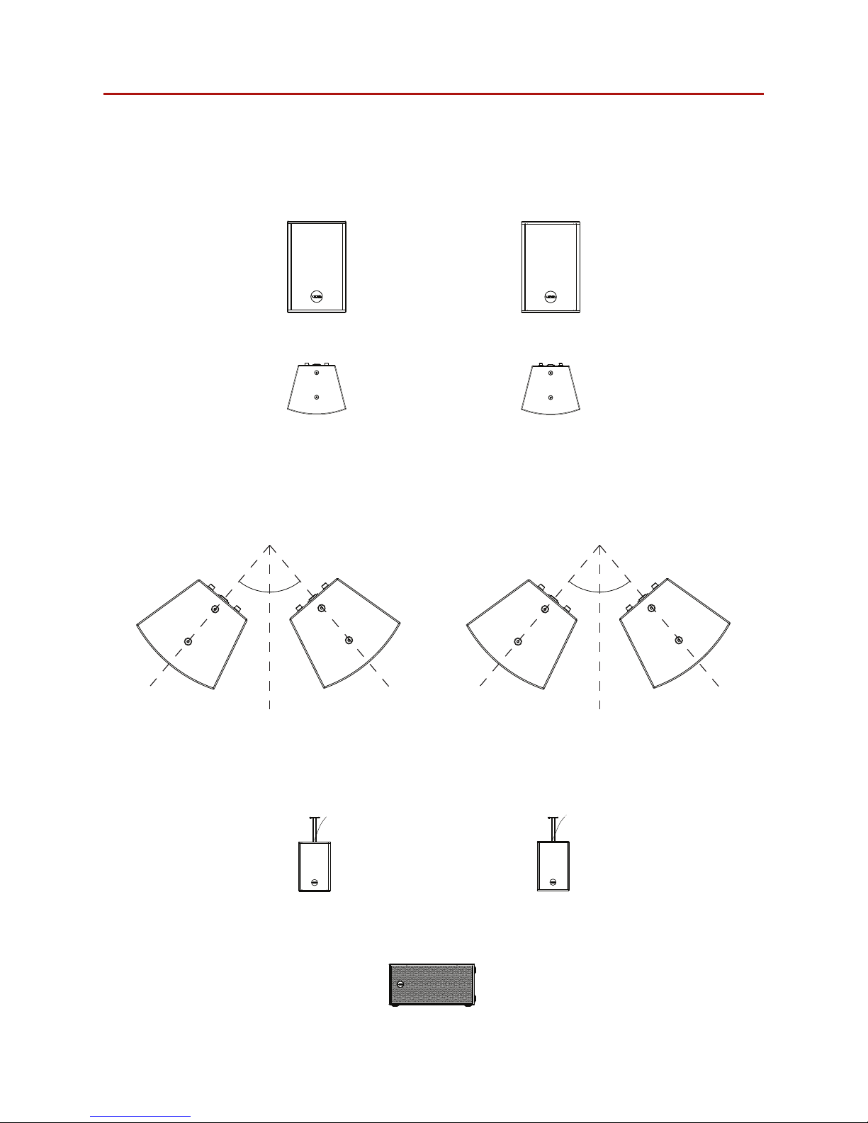
Figure 7.1: Loudspeakers single pair arrangement
40° 40°
Figure 7.2: Loudspeaker dual pair arrangement
For applications requiring wide horizontal coverage, use two loudspeakers in pairs. To ensure
an even coverage take the horizontal dispersion of the high frequency enclosure and divide it
by two and subtract 5° to determine the angle of separation. The example in figure 7.2 is of the
Venu Series where the horizontal dispersion is 90°, so (90° ÷ 2) - 5° = 40°.
40° 40°
7 System design
For permanent installation, it is recommended to fly high frequency loudspeakers for more
even coverage. This also allows co-located low frequency enclosures in a single block,
increasing sensitivity and providing more consistent bass coverage.
Figure 7.3: Venu ceiling mounting
7.1 System design principles
High frequency loudspeakers can be arrayed as a single pair facing forward to provide a wide
stereo image.
Page 19
Venu 210i User Guide V1.0
Page 19
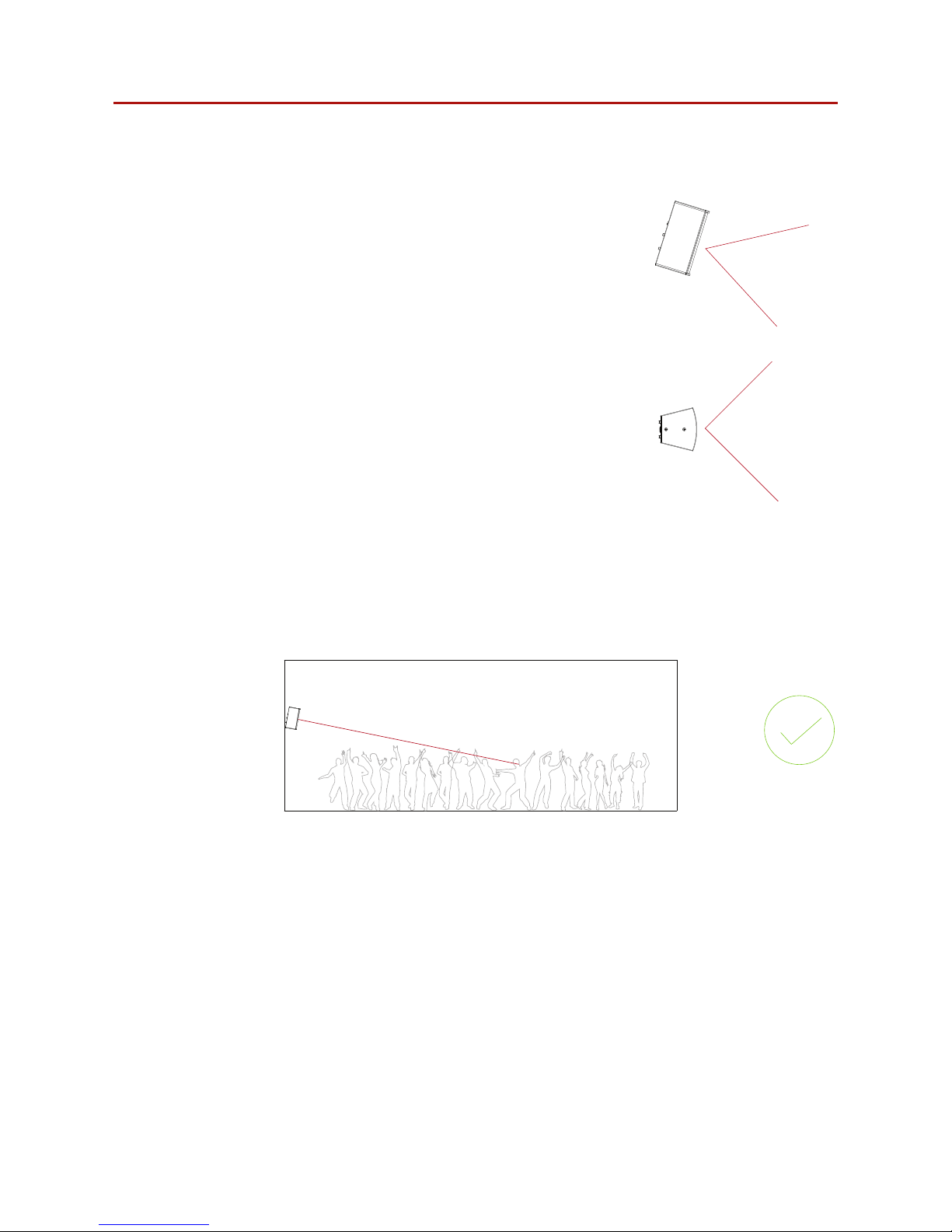
7.2 High frequency loudspeaker placement and positioning
When deploying high frequency loudspeakers, it is important
to consider the speakers’ vertical position to maximise
coverage in the vertical axis. Horizontal loudspeaker dispersion
figures dictate the coverage of the loudspeaker, left to right,
to the -3 dB points. The same can be said for the vertical
dispersion figure, but when applied to a listening area, this
figure dictates the audience area coverage front to back.
Vertical dispersion is often overlooked or not assessed
properly, resulting in ineciently deployed loudspeaker
systems that require more fill loudspeakers than are necessary
to achieve required coverage. Following are some basic
guidelines when considering the vertical position of your high
frequency loudspeaker.
With optimum vertical positioning and aiming applied the
loudspeaker system can be used at maximum eciency. With
a point source loudspeaker in this configuration the speaker
is placed 2m-4m from the ground, aimed half way to two thirds of the way back from the
audience area, as shown in figure 7.5. The applied aiming reduces unwanted reflections from
the ceiling and directs the highest energy concentration to the audience area requiring it most.
This is the most desirable position for the loudspeakers in this example.
Figure 7.5: Correct loudspeaker placement
Figure 7.4a: Vertical dispersion (side view)
Figure 7.4b: Horizontal dispersion (top view)
7 System design
Page 20
Venu 210i User Guide V1.0
Page 20
7 System design
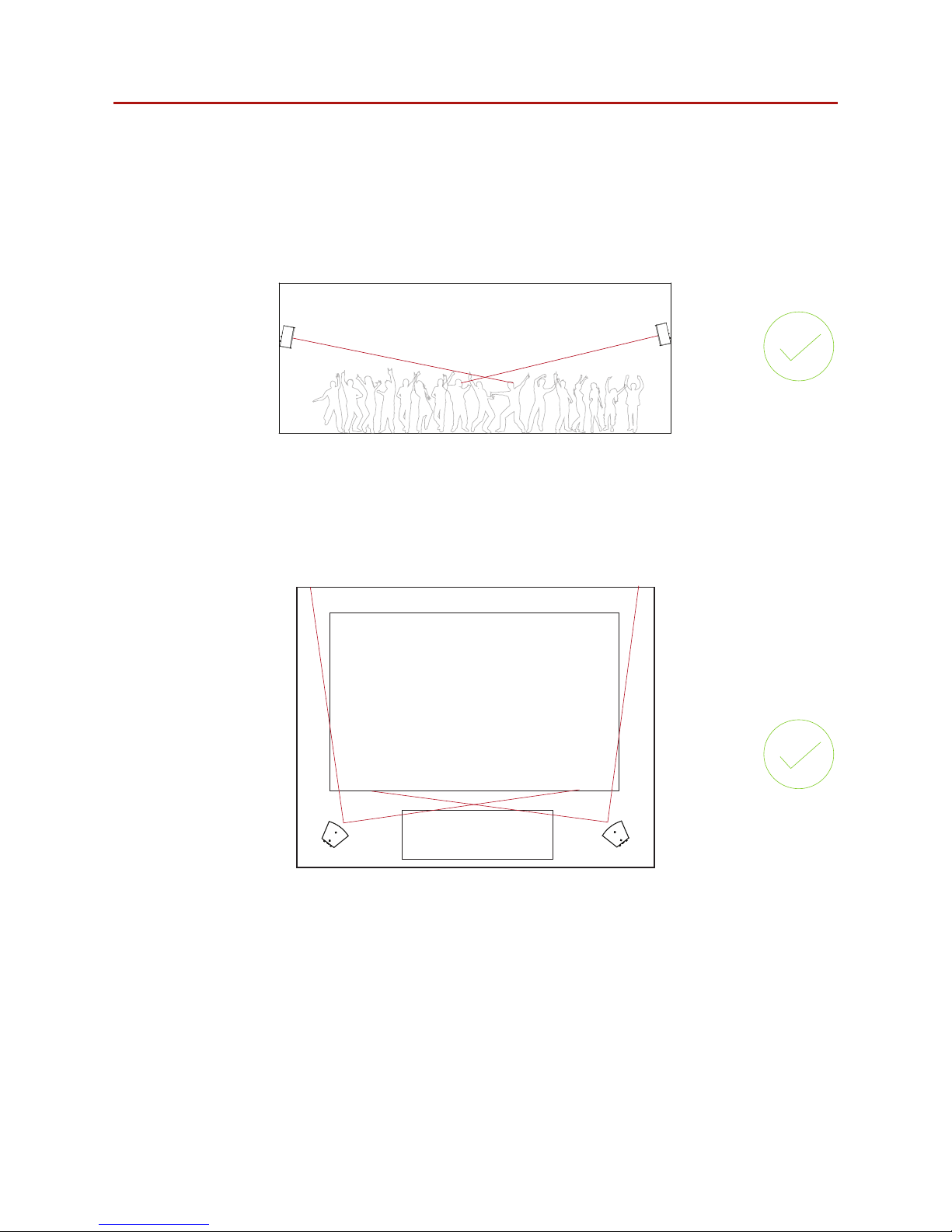
A multi-point loudspeaker system in a club/bar environment can be very pleasing for the
listener. However, it’s important that the processes applied to previous examples are still
implemented. In figure 7.6 you can see the loudspeakers have been positioned and aimed
optimally. When deploying a multi-point loudspeaker system, extra consideration must be
taken to counter unwanted room eects. Careful positioning and aiming of loudspeakers will
minimise room eects, while maintaining even coverage throughout the audience area.
Figure 7.6: Multi point loudspeaker arrangement
Audience
Stage
Figure 7.7: Correct horizontal dispersion
In the horizontal plane rotate the high frequency loudspeakers toward the audience area at
an angle such that the centre line of the dispersion from each loudspeaker meets about two
thirds of the way towards the rear of the audience area. This will help provide a wider coverage
and result in more of the power being used usefully.
Page 21
Venu 210i User Guide V1.0
Page 21
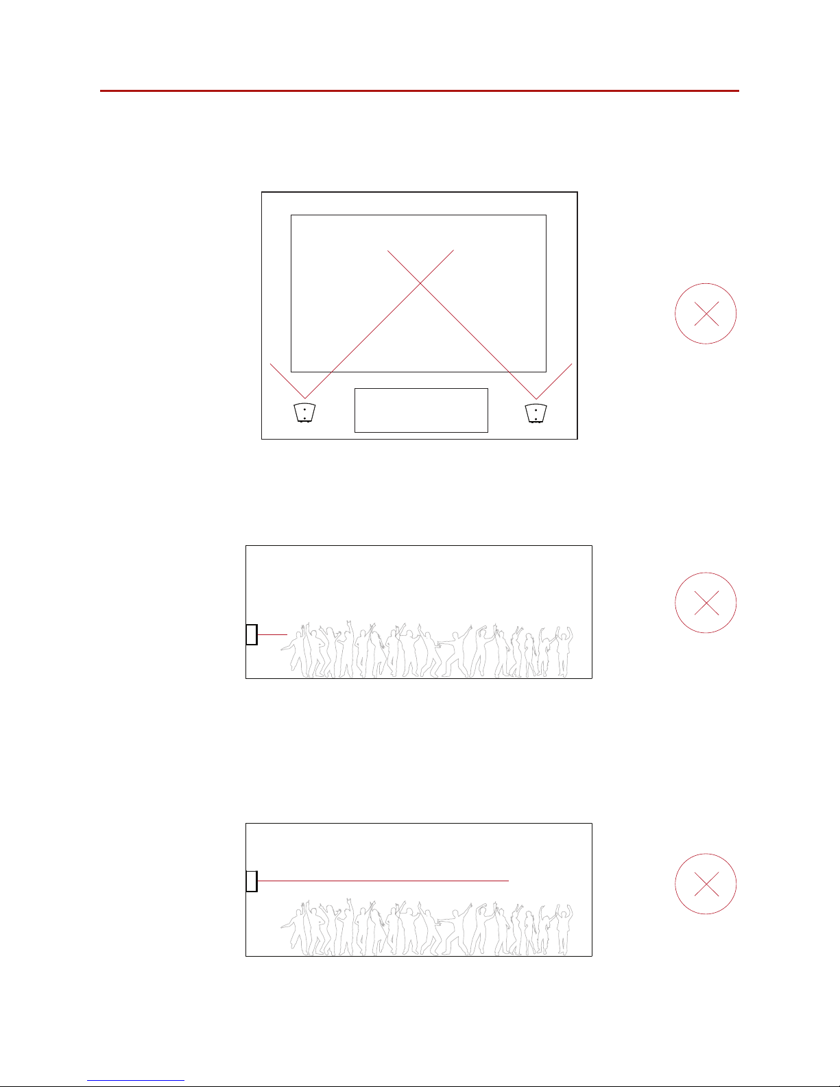
Figure 7.9: Incorrect loudspeaker placement
Figure 7.10: Incorrect loudspeaker placement
In figure 7.9 the loudspeakers vertical positioning is too low for the audience area. Mid
and high range frequencies are absorbed by the first two rows of people, resulting in poor
coverage and potential acoustic issues from room reflections.
Figure 7.10 shows the loudspeaker vertical position is optimal for the audience area but the
user hasn’t applied an aiming angle. In this case, a large portion of energy is directed at the
ceiling that could result in reduced intelligibility and unwanted room acoustic characteristics.
The shallow angle of attack will also induce refraction issues on a hot dance floor, leading to
reduced HF penetration at mid and far distances, again reducing intelligibility and coherence.
Audience
Stage
Avoid directing the high frequency loudspeaker straight forward. This will result in a proportion
of the power being directed towards the walls, creating possible reflective issues, as well as
causing a gap in coverage at the centre of the audience area.
Figure 7.8: Incorrect horizontal dispersion
7 System design
Page 22
Venu 210i User Guide V1.0
Page 22
7.3 Bass alignment - delay times
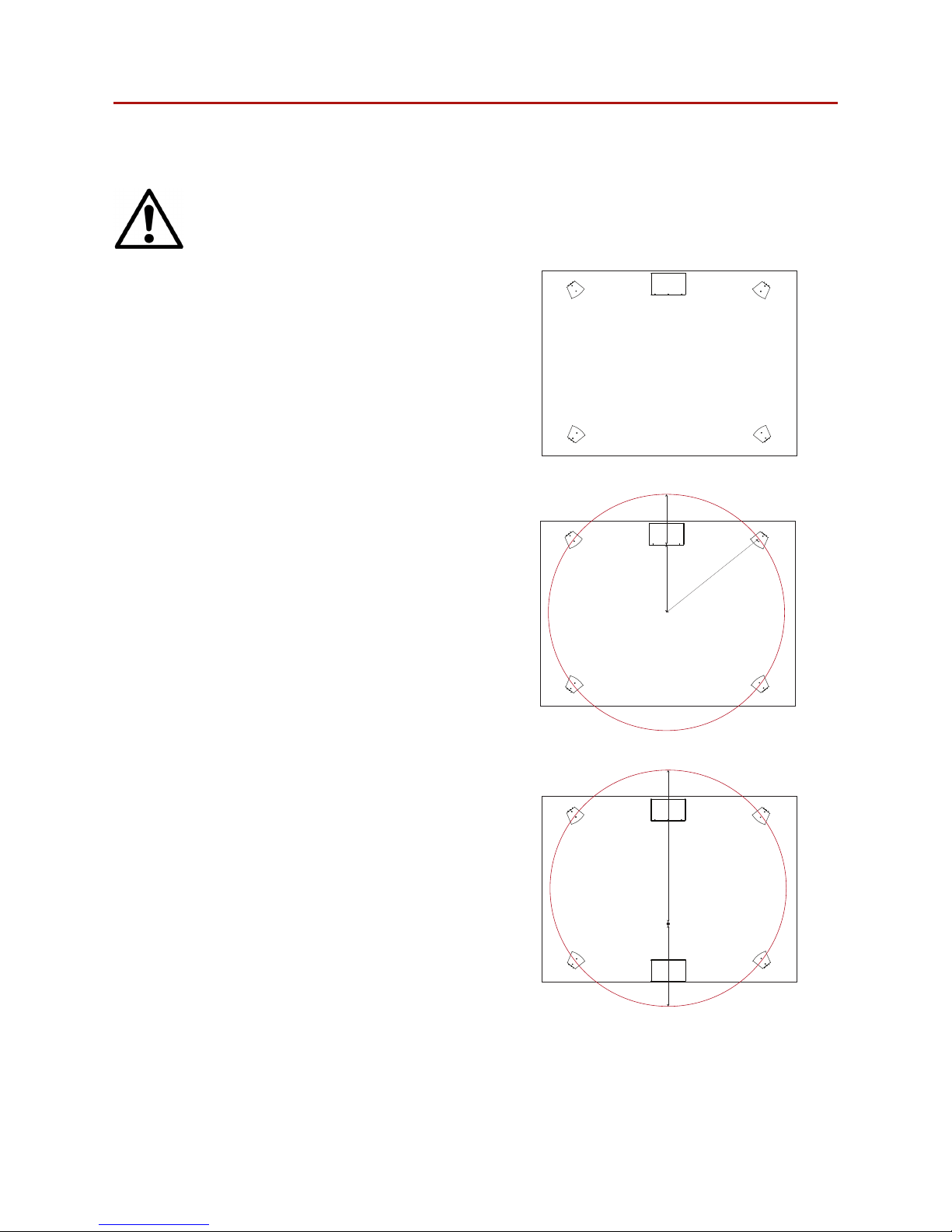
Note: All information given here is a guide and not a rule. Taking measurement on
site and using your ear are still the most reliable way to achieve the best results.
R
A
B
O
Figure 7.12: Bass alignment example 1
Figure 7.13 shows a second low frequency
enclosure added. Here we are looking to create
a secondary focal point at E. To calculate our
delay time we take distance D, which is point
E to the south edge of the circle, away from A,
which is E to the north edge of the circle, and
multiply by the delay time per metre. Or:
(A - D) x 2.9 ms/m = delay time.
E
A
D
Figure 7.13: Bass alignment example 2
7 System design
All four loudspeakers sit on a circle of radius R
with its centre point at O. The low frequency
enclosure is situated at a distance A from the
origin and a distance B from the circumference
of the circle. The distance B will determine the
delay required for the low frequency enclosure
of 2.9 ms per metre. So, in this example, if the
distance B is 2 m the a delay of 5.8 ms would be
required.
When designing loudspeakers and low frequency
enclosures layout within a space it is often
necessary to apply delay to optimise system
performance. In figure 7.11 we have a room with
four Venu loudspeakers and single low frequency
enclosure.
Figure 7.11: Bass alignment
Page 23

Venu 210i User Guide V1.0
Page 23
Void Venu 210i loudspeakers should only be serviced by a fully-trained technician.
No user serviceable parts inside. Refer servicing to your dealer.
8.1 Return authorisation
Before returning your faulty product for repair, please remember to get an R.A.N. (Return
Authorisation Number) from the Void dealer who supplied the system to you. Your dealer will
handle the necessary paperwork and repair. Failure to go through this return authorisation
procedure could delay the repair of your product.
Note that your dealer will need to see a copy of your sales receipt as proof of purchase so
please have this to hand when applying for return authorisation.
8.2 Shipping and packing considerations
• When sending a Void Venu 210i loudspeaker to an authorised service centre, please write a
detailed description of the fault and list any other equipment used in conjunction with the
faulty product.
• Accessories will not be required. Do not send the instruction manual, cables or any other
hardware unless your dealer asks you to.
• Pack your unit in the original factory packaging if possible. Include a note of the fault
description with the product. Do not send it separately.
• Ensure safe transportation of your unit to the authorised service centre.
8 Service
Page 24

Venu 210i User Guide V1.0
Page 24
9 Appendix
The loudspeaker shall be a sub-bass system consisting of two high power 10” (381 mm) direct radiating
reflex loaded low frequency (LF) transducers in a rectangular enclosure.
The low frequency transducers shall be constructed on a cast aluminium frame, with a treated paper
cone, high excursion 101.6 mm (4”) voice coil, wound with copper wire on a high quality voice coil
former, for high power handling and long-term reliability.
Performance specifications for typical production unit shall be as follows: the usable bandwidth shall
be 40 Hz to 150 Hz (±3 dB) and with a maximum on axis SPL of 130 dB peak (124 dB continuous)
measured at 1 m using IEC268-5 pink noise. Power handling shall be 1200 W AES at a rated
impedance of 4 Ω.
The system shall be powered by its own internal 1200 W dedicated power amplification module with
DSP management with two 600 W at 4 Ω full range outputs.
The enclosure shall be constructed from a 15 mm multi-laminate birch plywood finished in textured
polyurethane and shall contain fixture points for a pressed weather-resistant steel powder coated grille
to protect the low frequency transducers with the external dimensions of (H) 334 mm x (W) 684 mm x
(D) 530 mm (13.2” x 26.9” x 20.9”). Weight shall be 32 kg (70.5 lbs).
The loudspeaker system shall be a Void Acoustics Venu 210i.
Architectural Specifications
Page 25

Page 26

www.voidacoustics.com
Head Oce
Void Acoustics Research Ltd
Unit 15 Dawkins Road Industrial Estate
Poole
Dorset
BH15 4JY
England
+44 (0) 1202 666 006
Registered in England & Wales No. 07533536
North America
Void Acoustics North America
503-854-7134
 Loading...