

VoiceInterop AudioMate 360r User Manual

AM360r User Manual
revised 2014.02.29 for
Hardware Rev. DD
Firmware Version 1.00.26
AudioMate 360r User Guide
IP Voice Gateway for Land Mobile Radio
Table of Contents
Quick Start Guide .................................................................................................2
Gather Your Tools
Basic Configuration Steps
AudioMate 360r Product Tour ............................................................................3
Front Panel
Rear Panel
Installation ............................................................................................................5
Network Considerations
Bandwidth Consumption and CoDecs
Electrical Considerations
Configuration .......................................................................................................5
Network Address
Configuring by Web Browser
Global Configuration
Module Configuration
Status .....................................................................................................................12
Global Status
Module Status
AudioMate 360r Specifications ...........................................................................15
Appendix A - Interface Examples ........................................................................16
Ritron Nexus Radio Base
Motorola Waris Series
Appendix B Multicast Addressing Notes ............................................................18
Appendix C - WAVE Configuration ....................................................................19
AM360r
Multicast Configuration
Unicast Configuration
www.VoiceInterop.com
8000 N. Federal Highway, Suite 100, Boca Raton, FL, 33487 V: +1 561.939.3300
1

Quick Start
AM360 Configuration
Utility
www.voiceinterop.com
Register as a customer
Choose the Support tab.
Download AudioMate 360 IP
Address Assignment utility
AM360r User Manual
revised 2014.02.29 for
Hardware Rev. DD
Firmware Version 1.00.26
Quick Start Guide
Gather Your Tools
Web browser — Mozilla Firefox, Opera, Chrome, or Internet Explorer.
AM360 Configuration Utility — To find the address of each AM360 gateway, download the
AudioMate 360 IP Address Assignment utility from our web site, www.voiceinterop.com
under the Support tab. You must first register as an owner of an AudioMate 360 gateway to
be granted access.
NO soldering iron nor screwdriver is needed to set up the gateway, just a web browser and a
plan.
Basic Configuration Steps
Find the IP address ¤
Log in ¤
Set the RTP address and ports ¤
Check for proper control signals and logic levels on the radio interface ¤
Set audio levels with a partner listening ¤
Find the AudioMate IP Address
Use the AM360 (AudioMate 360) Configuration Utility to find the IP address that was
assigned by your DHCP server. Click the Locate button and select a unit from the list on the
left pane.
Log In to the AudioMate Unit with a Web Browser
Type the IP address of the desired AudioMate into the address bar of your web browser and
press Enter. The AM360 will prompt you for the user name and password. The factory values
are admin and password.
Set the RTP Address and Ports
The default AM360 settings might be all that you need to get going. If necessary, set the
Remote RTP Address, RTP Remote Port, and RTP Local Port to communicate with your audio
network. Refer to Appendix B for tips on selecting i.p. multicast addresses.
Check Control Signals
Ensure that the proper cable is connected between the AM360r and the radio. Set the COS
Polarity and PTT Polarity to match the needs of the radio. Check that the AM360r is able
to key the radio transmitter and that the radio is programmed to provide COR/COS/RUS/
Receive Activity indicator on the proper wire. Proper radio programming is critical.
Set Audio Levels With a Partner
Set the Transmit and Receive Gain to acceptable levels that make the radio transmissions
intelligble and pleasant to listen to. This test requires two people: one to talk and another to
listen.
See the Configuration section for detailed instructions.
www.VoiceInterop.com
8000 N. Federal Highway, Suite 100, Boca Raton, FL, 33487 V: +1 561.939.3300
2
tour
AM360r User Manual
revised 2014.02.29 for
Hardware Rev. DD
Firmware Version 1.00.26
AudioMate 360r Product Tour
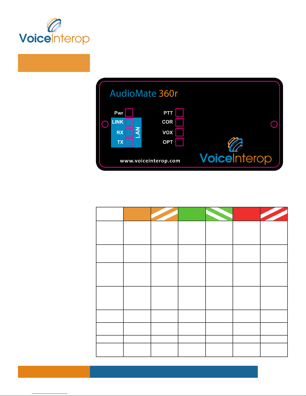
Front Panel
Front Panel Indicators
All front panel indicator LEDs can display one of seven color states: OFF, RED, RED FLASHING,
GREEN, GREEN FLASHING, AMBER and AMBER FLASHING each of which can be used to
indicate a different condition within the AudioMate 360r.
LED Amber Amber
flashing
Pwr
(Power)
Link
Rx
Tx
PTT
COR
VOX
Opt
Booting,
awaiting
DHCP
address
N/A Check
Buffering
audio from
IP network
N/A N/A N/A N/A Sending
N/A N/A N/A N/A M-lead
COR/COS
inhibited
Enabled N/A Active N/A N/A N/A
N/A N/A Anti-chirp is
N/A Normal
LAN cable
connection
N/A Playing rcvd
N/A COR input is
(Option)
Green Green
flashing
N/A Boot error
operation
LAN
connection
OK
RTP stream
out radio
port
active
active
AMCP data
traffic rcvd
N/A N/A N/A
N/A N/A N/A
N/A N/A N/A
Red Red
flashing
N/A
(view boot
via USB
serial port)
N/A N/A
N/A
RTP stream
to IP
network
N/A
asserted
www.VoiceInterop.com
8000 N. Federal Highway, Suite 100, Boca Raton, FL, 33487 V: +1 561.939.3300
3
Firmware Version 1.00.26
Front Panel Connections
There are no connections to the front panel of the AudioMate 360r.
Front Panel Controls
There are no input controls on the front panel of the AudioMate 360r.
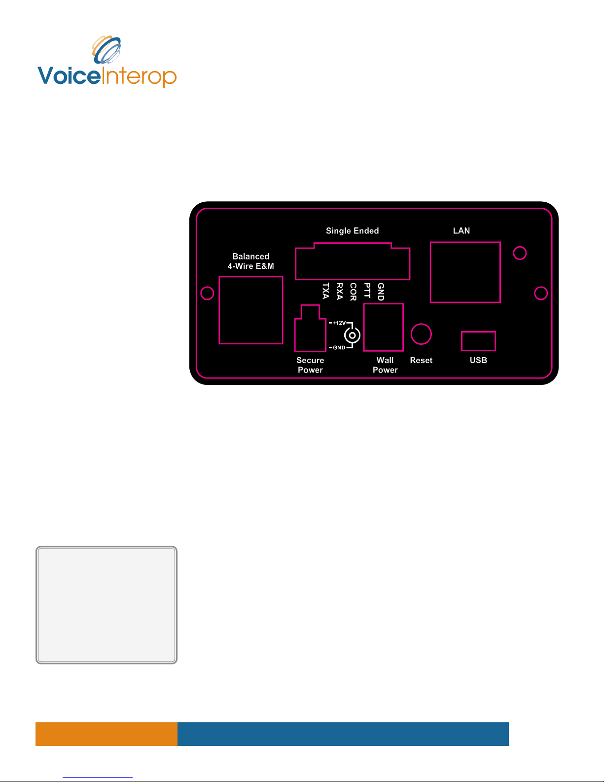
Rear Panel
AM360r User Manual
revised 2014.02.29 for
Hardware Rev. DD
Single-Ended Connector
The green 5-pin Single-Ended
connector on the rear of the
AM360r mates with Dinkle
part #EC350VM-05P for the
secured screw type
part #EC350V-05P for the
plain type.
Rear Panel Indicators
LAN Port — The LAN jack has two built-in lamps: a solid green one indicating that an
electrical link has been established, the other flashing green indicating packet activity.
Rear Panel Connections
-Wire Balanced — This RJ-45 port provides a balanced 600 ohm transformer-coupled
audio connection to 2-way radios and telephone lines. There are multiple standards for
connections to a radio using the RJ-45. The electrical specifications and pin assignments for
the AudioMate 360r balanced audio connector are given in Appendix A, along with interface
examples. Be careful not to connect an Ethernet cable to the balanced audio port, as they
both employ RJ-45 jacks.
Single Ended — Allows connection of single-ended audio and control signals from popular
2-way radios via a secured 5-pin plug. This plug accepts stranded or solid wire. All signaling is
single ended, referenced to ground. The pin assignments and electrical specifications for the
AudioMate 360r Analog connector are given in Appendix A, along with interface examples.
LAN — Standard 10/100BaseT Ethernet port with pin-outs following the AT&T T568B
specification. A standard Category 5 LAN cable connects it to an Ethernet switch. Be careful
not to connect the balanced audio cable to the LAN port, as they both employ RJ-45 jacks.
USB — (Factory use only)
V — 12 Volt d.c. input, tip is positive, ring is negative. The supplied power adapter converts
120 Volt a.c. main power to 12 Volts d.c. at 500 mAmps maximum, suitable for one gateway.
The power plug is a commonly available 2.1mm inner diameter and 5.5mm outer diameter.
www.VoiceInterop.com
8000 N. Federal Highway, Suite 100, Boca Raton, FL, 33487 V: +1 561.939.3300
4

inStallation
AM360r User Manual
revised 2014.02.29 for
Hardware Rev. DD
Firmware Version 1.00.26
The Mate-N-Lok jack is connected in parallel to daisy chain other AM360 gateways from a
larger power supply. The top 2 pins are +12 Volts, the bottom two are Ground.
Rear Panel Controls
Reset — This recessed push button reboots the processor in the AudioMate 360. Depress
using a pen or any object with a small tip. The length of time that it is held depressed
determines the type of reset:
Quick Reset – A momentary press performs a simple reboot.
Factory Reset – To reset the unit to its factory-default configuration press and hold the
Reset pushbutton until the OK light goes from AMBER to GREEN. While the AudioMate
360 is awaiting an address from a DHCP server this could take as much as 60 seconds. In
order to ensure that the device loads factory default settings the Reset button must be
held this entire time, until the OK light changes from AMBER.
Installation
Network Considerations
In the typical AudioMate installation all endpoints are contained entirely within a corporate
LAN, or participate via a WAN link, either unicast through a VPN or an engineered MPLS
network, for example.
config
Bandwidth Consumption and CoDecs
The G.711 codec (encoder/decoder algorithm) consumes approximately 84kilobits/second
each direction per stream. The GSM Full Rate codec consumes less bandwidth, but produces
lower quality audio and is not suitable for tone remote applications. In modern networks we
recommend using the G.711µ Law for almost all applications.
Electrical Considerations
The AudioMate 360 gateways are powered by 12 Volts d.c. from the provided plug-in power
supply or by a 12 Volt battery with float charging system. In either case, the power must
be clean and free of a.c. noise components and interruptions. The supplied power module
should be plugged into an uninterruptible power supply (UPS) for trouble-free service. If a 12
Volt battery/charger system is used, the charger must keep noise to less than 12mVp-p.
If multiple AM360 gateways are powered by a single supply, it must provide sufficient
current. A maximum of 8 AM360 gateways may be connected in daisy chain fashion using
the Mate-N-Lok connectors.
Configuration
Each unit requires two groups of configuration data: one group that is common across the
AudioMate 360 family and a second group that is specific to the application of the unit.
Network Address
The units are shipped with DHCP enabled and will accept whatever address is assigned
by your DHCP server. On startup the AM360 will wait up to 60 seconds for a DHCP server
to assign its IP address. On timeout the AM360 will assign itself a default IP address of
192.168.0.254 and a netmask of 255.255.255.0.
www.VoiceInterop.com
8000 N. Federal Highway, Suite 100, Boca Raton, FL, 33487 V: +1 561.939.3300
5
AM360 Config Utility
The Address Finder utility is
available to registered users
by logging in to our web site:
www.voiceinterop.com
Click the Support tab.
AudioMate 360 Login
username = admin
password = password
AM360r User Manual
revised 2014.02.29 for
Hardware Rev. DD
Firmware Version 1.00.26
Locating the AM Address
Use the AudioMate 360 Configuration utility to locate the addresses of your units in
preparation for configuration. Individual AudioMate 360 units are configured via web
browser pointed to the management IP address of the unit. The Address Finder utility is
available by logging in to our web site
www.voiceinterop.com
Click the Support tab to find the link to download the AM360 Configuration Utility.
Open the AM360 Configuration Utility and click the Locate button and select a unit from the
list on the left pane. The IP address of each unit is to the right of each minus sign.
Configuring by Web Browser
Type the address of the desired AM360 unit into the address bar of your web browser. (At
the time of this writing the freely available Mozilla Firefox web browser provides smoother
operation for these purposes.)
Logging In
Like most network devices, the AM360 is protected by a password. The factory default for
user name is admin and the factory default password is password.
When prompted by the web interface enter the appropriate user name and password. If they
were accepted you will see a two part screen with a menu panel on the left pane and a page
labeled AM Status on the right pane.
www.VoiceInterop.com
8000 N. Federal Highway, Suite 100, Boca Raton, FL, 33487 V: +1 561.939.3300
6

AM360r User Manual
revised 2014.02.29 for
Hardware Rev. DD
Firmware Version 1.00.26
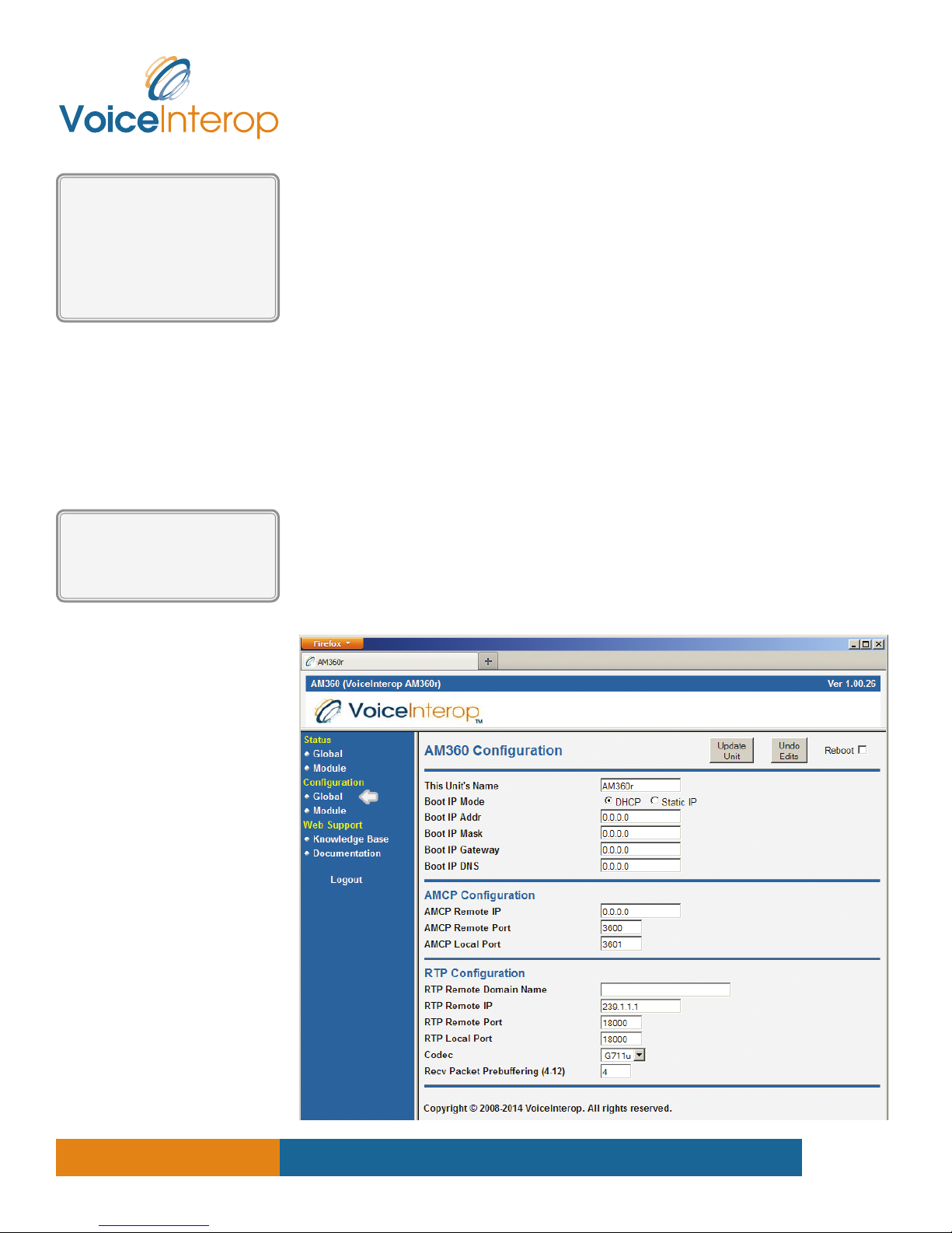
Global Configuration
In the menu pane on the left, locate the Configuration heading and click the link Global
under it. The screen labeled AM Configuration should appear in the right pane.
You may safely ignore the AMCP settings.
This Unit’s Name allows you to set a memorable name to identify this unit among the others
on your network. This field accepts standard alphanumeric characters.
Boot IP Mode selects between automatic IP address assignment by your DHCP server or
static IP address assignment specified in the fields that follow. If you select Static IP and
then click the Update Unit button, the IP Boot fields will be filled with current values. If
you select DHCP and click the Update Unit button the fields will be returned to 0.0.0.0
which indicates DHCP. Note that editing and saving the Boot IP fields has no effect on
communications until you reboot the unit.
Boot IP Addr
After changing the IP address
of the AM360r you must
reboot the unit to make the
new IP address effective.
Also remember to change
the address in your browser!
Multicast Addressing
Appendix B has more detail
on selecting multicast
addresses with pointers to
reference sources.
Boot IP Addr sets the static unicast management IP address used to configure this unit.
Default is 0.0.0.0 for DHCP. Once you change this address, set the mask, update and reboot
the unit, remember to point your web browser to the newly assigned address.
Boot IP Mask sets the netmask or network portion of the IP address. In a typical Class C
network this will be 255.255.255.0 while the default value is 0.0.0.0 for DHCP use. If you set a
static IP address you must also set this field to represent the size of your network.
Boot IP Gateway sets the next-hop gateway router that will carry the AM360r packets to
other networks. If you set a static IP address you must also set the gateway to the gateway
router on your network. The default value is 0.0.0.0 for DHCP use.
Boot IP DNS sets the IP address of your DNS server, if needed. Typically this address will be
the same as your default gateway in small networks. Default is 0.0.0.0 for DHCP use.
AMCP Configuration
You may safely ignore the AMCP settings.
RTP Configuration
RTP Remote IP is the address to which audio packets will be sent. In multicast networks
type the multicast group which will share audio with other units on the same multicast
group. The Class D multicast range lies between 225.0.0.0 and 239.255.255.255
with numerous restrictions and considerations. Consult Appendix B for more information
on multicast address assignment. For point-to-point unicast links type the unicast address
(Boot IP Address) of the other end of the link, not this unit. Default is 239.1.1.1 multicast
group.
RTP Remote IP
is the address of other unit
if using unicast, not the one
that you are configuring.
www.VoiceInterop.com
RTP Remote Port is the IP port number assigned to this channel on the other end of the
link. This should be an even number between 16384 and 65534. Default is 18000.
RTP Local Port is the IP port number on which this AM360 will listen and is typically identical
to the RTP Remote Port number. Default is 18000.
Codec should be set to Gu for most applications. Other choices are Ga for G.711 A-law,
and GSM for GSM 6.1 full rate. The G.711 codecs use about 84 kbits/second each way while
the GSM codec uses about 13 kbs/sec. Default is G.711 µ-law codec.
8000 N. Federal Highway, Suite 100, Boca Raton, FL, 33487 V: +1 561.939.3300
7
 Loading...