

Page 1

Ikarray-12
Line-Array
Manual
Page 2

Herzlichen Dank,
dass Sie ein Voice-Acoustic Produkt gekauft haben.
Seit dem Jahr 2006 entwickeln wir unsere Produkte
in der Überzeugung, dass es auf die Details ankommt.
Wir wünschen Ihnen viel Freude mit diesem Produkt.
Thank you very much,
for purchasing a Voice-Acoustic product.
Since 2006 we have been developing our
products in the rm belief that details matter.
May we wish you a lot of pleasure with this product.
Muchas gracias
por haber comprado un producto de Voice-Acoustic.
Desdel año 2006 estamos desarrollando nuestros productos
estando convencidos, que son los detalles que cuentan.
Le(s) deseamos mucha alegría usando este producto.
Merci beaucoup
d´avoir acheté un produit Voice-Acoustic.
Depuis 2006, nous développons des produits
avec la ferme conviction que les détails comptent.
Nous vous souhaitons beaucoup de plaisir à utiliser ce produit.
Page 3

Contents
Introduction
General Safety Instructions 4
Care 4
Transport and storage 4
Warranty 4
Components 5
Technical data 6
Connections 6
Setup 7
Connecting cables 7
Operation 7
Working with Ikarray-12
Rigging frame components 8
Connection of 3 elements to Ikarray-12sp 9
Assembly and dismantling 10
Stacked assembly (Stacking) 11
Overview Accessories 12
Manufacturer‘s declaration
Imprint 13
Page 4

Introduction
General Safety Instructions:
Loudspeakers produce a static magnetic eld even if they are not connected or are not in use. Therefore make
sure when erecting and transporting loudspeakers that they are nowhere near equipment and objects which
may be impaired or damaged by an external magnetic eld. Persons with cardiac pacemakers must maintain a
safe distance.
The minimum recommended safety clearance is 1 m.
Never stand in the immediate vicinity of loudspeakers driven at a high level. Professional loudspeaker systems
are capable of causing a sound pressure level detrimental to human health. Seemingly non-critical sound levels
(from approx. 90 dB SPL) can cause hearing damage if people are exposed to it over a long period.
All connected cables must be laid in such a way that they cannot be crushed by objects and that nobody can
step on them! Replace damaged cables immediately and do not use them!
Use only accessory parts specied by Voice-Acoustic or original accessory parts from Voice-Acoustic. Check all
cabinets and accessories regularly for wear and replace them if necessary.
Do not set up the loudspeakers in places where they are permanently exposed to moisture, dust, dirt or direct
sunlight.
Care
Wipe the surface of loudspeakers only with a damp cloth and pure water. In case of heavy pollution, repeat the
above procedure several times if necessary. Do not use any chemical additives or aggressive detergents, as
these may harm and damage the surfaces.
Transport and storage
When transporting and storing the unit, it is important to ensure that the surface and front grill of the loudspeaker are not damaged. Moisture can penetrate through exposed wood surfaces and cause the wood to swell.
A bent or broken front grill will no longer adequately protect the sensitive speaker membranes. In addition,
appreciable dust deposits may considerably impair the functionality of a loudspeaker membrane. For this reason, the loudspeakers should be transported and stored in a safe, careful, dry and largely dust-free manner.
The following accessory parts for transport and storage are available from Voice-Acoustic:
■ Transport and rain cover for 4 x Ikarray-12 in ground stacking (Art.-Nr. 501201000)
■ Dolly for transport up to 4 x Ikarray-12 (Art.-Nr. 501204000)
Note: The original packaging is unsuitable as permanent storage and transport packaging!
Warranty
The warranty period is 24 months from date of delivery.
On our choice we will eliminate any lack of conformity with repair or with replacement of the faulty goods. The
place of performance for warranty services is Voice-Acoustic headquarters in Dörverden. In case of remedy of
defects, the buyer shall bear all costs resulting from transportation of the goods to Voice-Acoustic headquarters
in Dörverden.
The ordering party is not entitled to remedy the defect by itself or to organise a replacement and to charge
such activities to Voice-Acoustic. In case of self remedy by the ordering party the warranty given by VoiceAcoustic becomes void.
Warranty doesn’t apply to parts of wear and tear, such as threaded points and the SpeakON
®
connectors.
Page 4 of 13Manual Ikarray-12 - 2018-07 EN
Page 5
Introduction
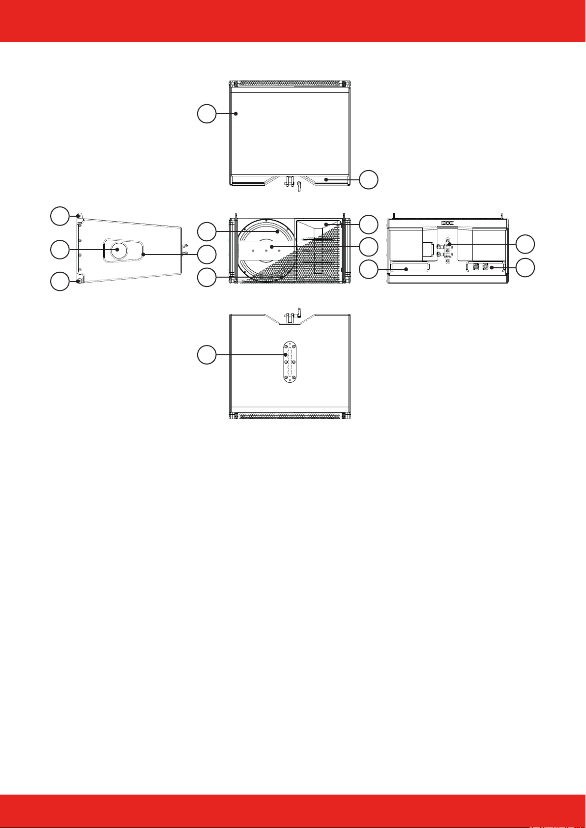
Components
4
9
1
5
2
3
1. Upper connection point ight mechanics
2. Bass reex port
3. Lower connection point ight mechanics
4. 30 and 15 mm multiplex cabinet, polyurea coating in RAL 9005
5. 12“ Neodym woofer
6. Recessed grip on both sides
7. Front grille 1 mm with 10 mm acoustic foam
8. Flying track (operation with a maximum of two Ikarray-12 among each other)
9. Rear recessed grips
10. 1,4“ Neodym compression driver on double-twin waveformer
11. V-Plug
12. Type plate with serial number
13. Mounting points for thread mechanism
14. Connector panel with two SpeakON
6
7
8
®
connectors
10
11
12
13
14
Page 5 of 13Manual Ikarray-12 - 2018-07 EN
Page 6
Introduction
Technical data
Components 1 x 12“ Neodym woofer (LF) with 3“ voice coil
1 x 1,4“ Neodym compression driver (HF) with 3“ voice coil
Frequency response 49 Hz - 18.5 kHz (- 10 dB)
62 Hz - 17 kHz (+/- 3 dB)
Coverage range (h x v) 100° x 6°
Powerhandling LF: 400 W AES / 800 W program / 1.600 W peak at 16 Ω
HF: 110 W AES / 220 W program / 440 W peak at 16 Ω
Sound pressure 130 dB SPL AES / 133 dB SPL program / 136 dB SPL peak
Dimensions / Weight 325 (h) x 605 (w) x 520 mm (d) / 31,90 kg
Finish Polyurea coating in RAL 9005
Connections
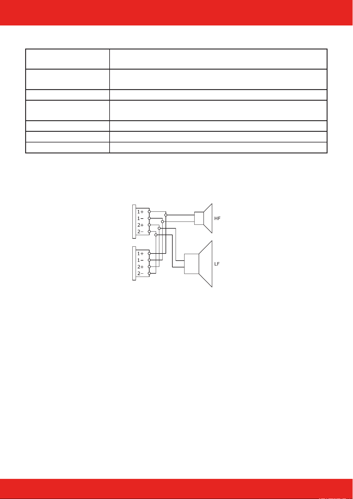
The speaker has four loop-through Neutrik NL4 SpeakON
pins. Additional loudspeakers can be looped through via the second connector.
®
IN/OUT connectors. They use the 1+/1- connection
Page 6 of 13Manual Ikarray-12 - 2018-07 EN
Page 7
Introduction
Setup
The Ikarray-12sp line array is designed for vertical operation. A variety of accessories is available from VoiceAcoustic to securely attach the loudspeaker safely on tripods, distance rods or hanging it from on trusses,
ceilings and walls. Ensure that the loudspeakers are securely attached to prevent personal injury and damage
of property.
Connecting cables
When connecting the cables to the loudspeaker, ensure that the polarity (+/-) and pin assignment (1/2) is
correct. Incorrect connection results in a signicant change in the loudspeaker sound characteristics and may
damage the compression driver.
The two connection sockets on the back of the loudspeaker can be used to link multiple loudspeakers on a
single amplier. Note that parallel connection reduces the total impedance (Ω) seen by the amplier. The total
impedance of loudspeakers connected in parallel must not drop below the minimum operating impedance of the
amplier.
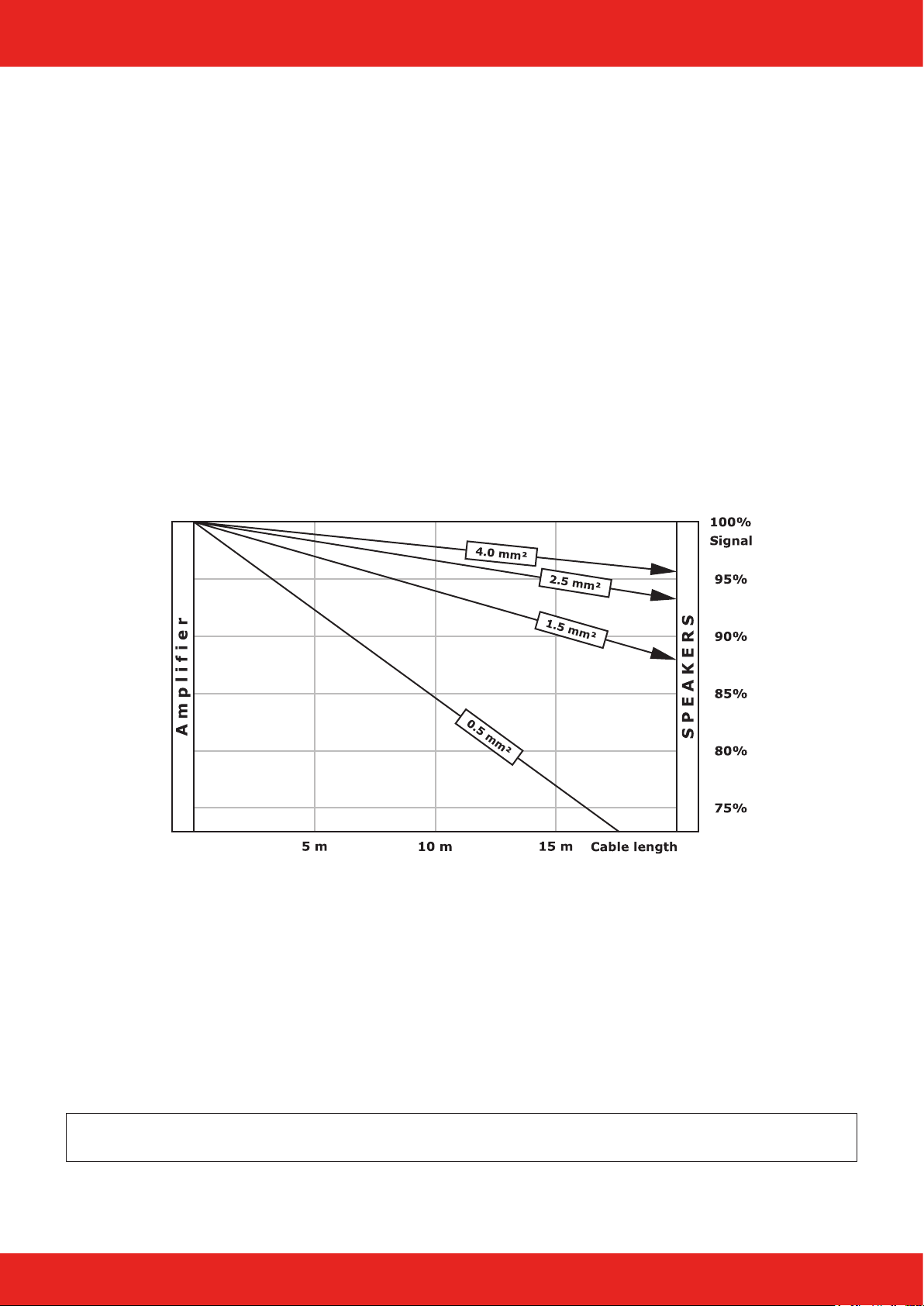
Voice-Acoustic recommends to use the available 4 x 4 mm² Speakon cables for mobile use.
We recommend wiring the basses with at least 4 mm² in installations. The cables of the tops in installations
must be suciently dimensioned according to impedance, power and cable length.
Simplied display without consideration of loudspeaker impedances
Operation
The Ikarray-12 is exclusively intended for operation with Voice-Acoustic system electronics with internal DSP
controller: the HDSP power ampliers or powered by the free 800 W amplier channels of the self-powered subwoofers.
Make sure the appropriate preset has been selected before connecting the speaker to the system power amp or
self-powered subwoofer.
Using the wrong preset can damage parts of the loudspeaker.
Note: If the Ikarray-12 is not operated on the intended Voice-Acoustic system electronics, the manufacturer‘s warranty for the loudspeaker expires!
Page 7 of 13Manual Ikarray-12 - 2018-07 EN
Page 8
Working with Ikarray-12
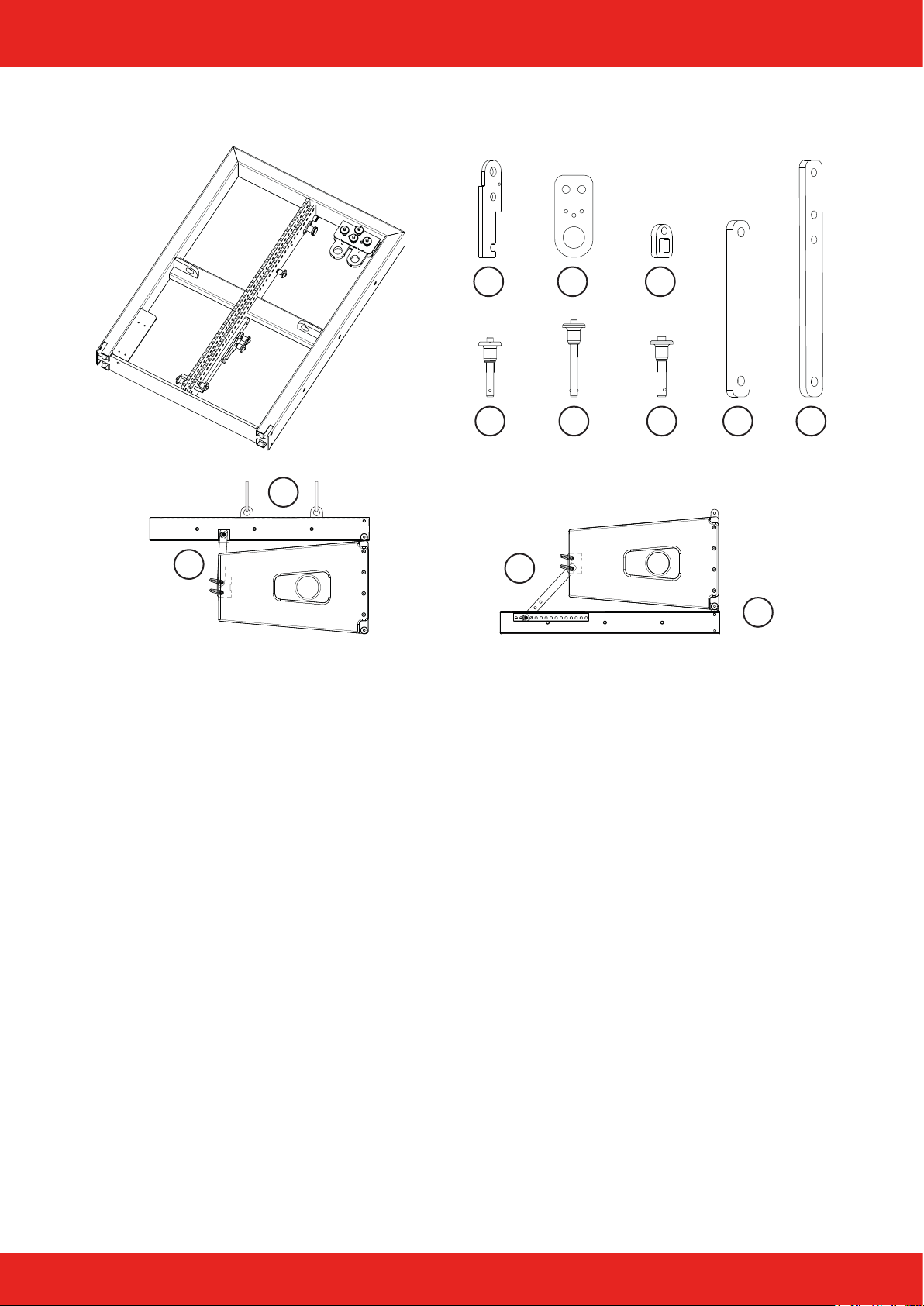
Rigging frame components
2 x2 x
1 x
2
7
1. Groundstacking Adapter / Receptacle
2. Load anchor
3. Cable holder
4. Ball locking bolt Ø 8 mm / Clamping area 30 mm
5. Ball locking bolt Ø 8 mm / Clamping area 50 mm
6. Ball locking bolt Ø 10 mm / Clamping area 30 mm
7. Holding bar short for ight operation
8. Holding bar long for stack operation
1 2 3
1 x
4 x4 x
4 5 6 7 8
8
1 x
1 x
1
Page 8 of 13Manual Ikarray-12 - 2018-07 EN
Page 9
Working with Ikarray-12
Connection of 3 elements to Ikarray-12sp
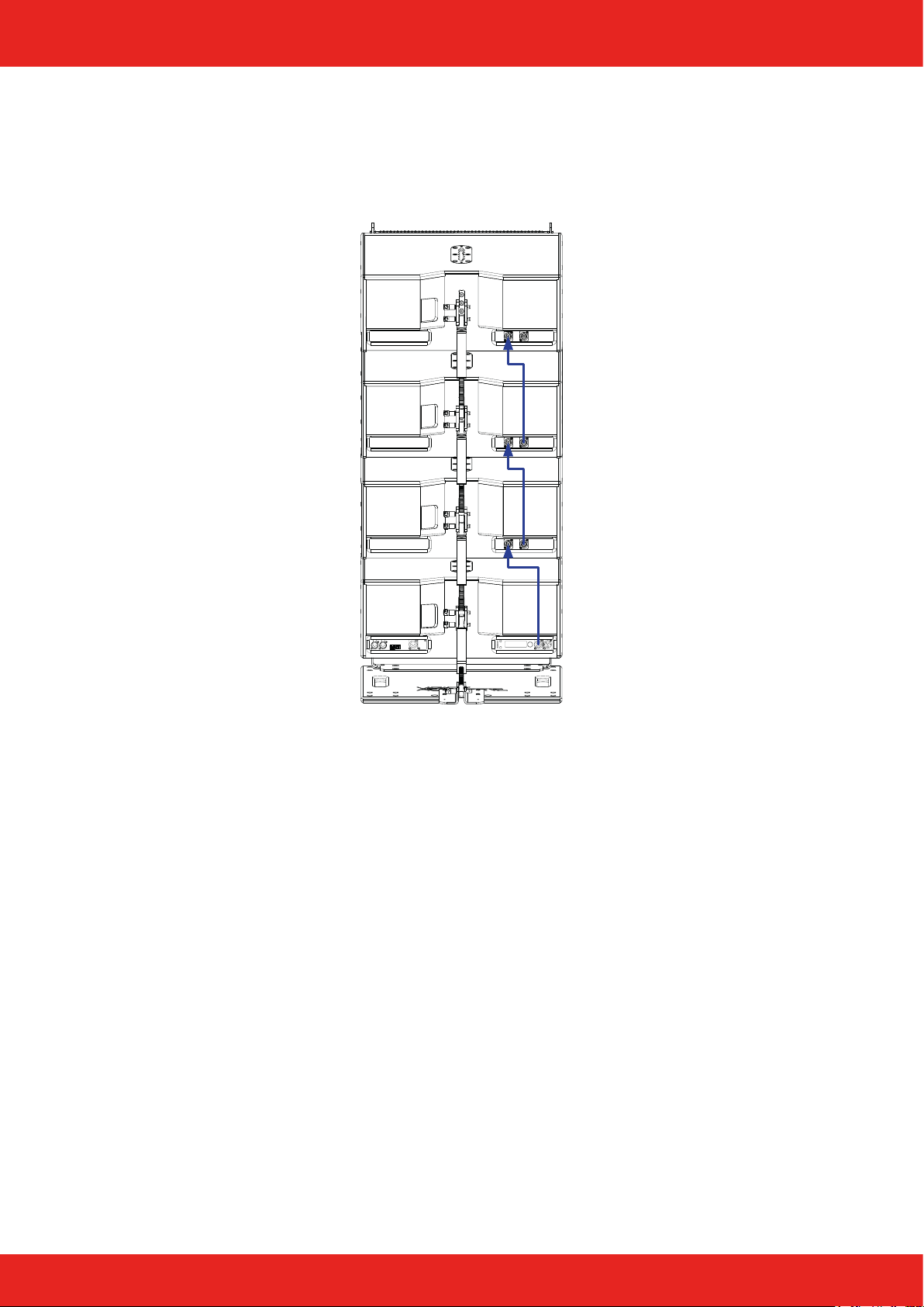
The three elements are operated bi-amping on two channels of the Ikarray-12sp. Thus, both paths can be
limited separately, ltered optimally and dierences in running time can be compensated. The woofer and the
tweeter are designed in 16 Ω . Three Ikarray-12 can be looped through with a 4-pin cable and operated in parallel from the same amplier channels at 4 Ω.
Pin assignment of the Speakon socket:
Speakon 1+/1- OUT CH2, 800 W
Speakon 2+/2- OUT CH1, 2.400 W
Page 9 of 13Manual Ikarray-12 - 2018-07 EN
Page 10
Working with Ikarray-12
Assembly and dismantling
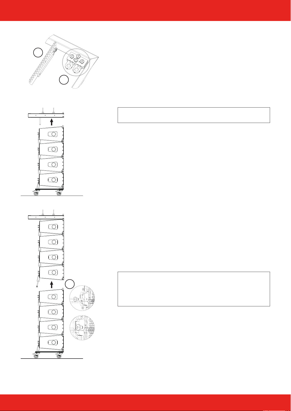
Positioning the load adapters
B
A
1. Calculate the correct position of the load adapters with the
EASE Focus 3 simulation software. In this calculated position it
is guaranteed that the array will later hang at the desired angle
and the sound will be radiated correctly.
2. Remove one of the two load adapters from the parking position
(A) and place it at the hole position (B) in the ying frame determined by the simulation software. Proceed accordingly with
the second load adapter.
Note: Always secure the two load adapters with two ball locking
bolts!
3. The rigging frame is now attached to the chain hoist with one
or two suciently dimensioned shackles (BGV C1) according to
the simulation.
Assembling a speaker array
1. Position the dolly under the ying frame to establish a connection. Secure the connection with the ball locking bolts. Check
all ball locking pins for correct seating and locking.
2. The dolly is unloaded via the chain hoist and released via the
front and rear locking pins of the lowest element.
3. The setting angles of the individual Ikarray-12 elements are
determined with the simulation software.
4. The spindle of the rear thread mechanism has a scale of 0° to
10°. The setting value can be taken from the corresponding
printout of the calculations.
5. Once the angle has been set and the loudspeakers are wired,
the row that is already hanging is raised in order to attach the
next elements accordingly.
6. Always connect all elements rst using the front locking bolts
(C) and only make the angle when the connection is secure.
Note: For large line lengths, this procedure may be unfavorab-
C
le, especially if the lowest elements are angled strongly. These
elements are then individually appended to the previous line at
working height from below. This also applies if no ground-level
access to the ying point is possible.
7. Basically, the disassembly of the array takes place in reverse
order to the assembly.
8. The strongly angled elements are removed again individually at
working height.
Page 10 of 13Manual Ikarray-12 - 2018-07 EN
Page 11
Stacked assembly (Stacking)
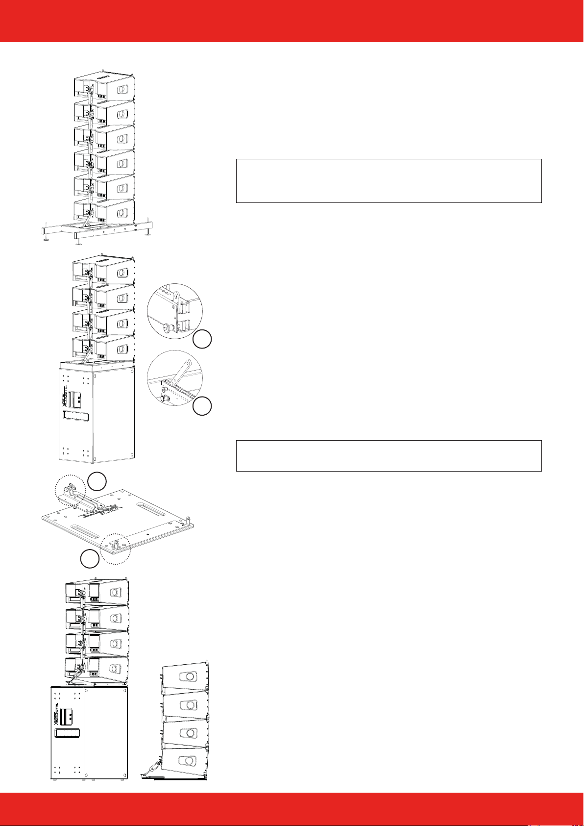
Stacked on rigging frame
1. The outriggers are available as optional accessories and are
used to ensure stability, compensate for uneven ground and
align the frame when the ying frame is not used lying on a
Paveosub-118 or 218.
Note: With outriggers up to six elements can be operated on top
of each other, if the ying frame lies on a bass, there must not
be more than 4 elements!
2. Remove the two groundstacking adapters from their parking
positions and insert them into the front of the ying frame.
3. Place the lower speaker on the two groundstacking adapters
(A) and secure the connections with two ball locking bolts.
4. Lift the rear of the speaker, align the bracket with the hole for
the desired angle and secure the connection with the ball lock
pin (B).
5. The following Ikarray-12 elements are always rst secured at
the front with the ball locking bolts and then connected and
A
aligned with the thread mechanism at the rear.
6. Wire the array.
Stacked on stackboard
B
D
C
1. Position the stackboard on a subwoofer or where you want to
place the line array.
Note: With the Stackboard up to four elements can be operated
on top of each other!
2. Place the lower speaker on the two front groundstacking
mounts (C) and secure the connections with two ball locking
bolts.
3. Raise the rear speaker and secure the rear threaded mechanism with the ball lock pin (D).
4. The following Ikarray-12 elements are always rst secured at
the front with the ball locking bolts and then connected and
aligned with the thread mechanism at the rear.
5. Wire the array.
Page 11 of 13Manual Ikarray-12 - 2018-07 EN
Page 12
Working with Ikarray-12
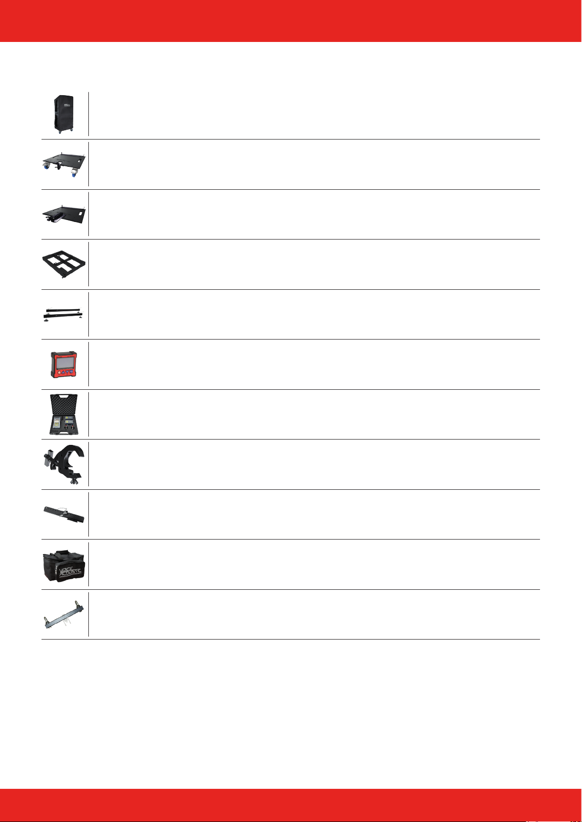
Overview Accessories
Transport and rain cover for 4 x Ikarray-12 in ground stacking (Art.-Nr. 501201000)
Dolly for transport up to 4 x Ikarray-12 (Art.-Nr. 501204000)
Stackboard for installation up to 4 x Ikarray-12 (Art.-Nr. 501205000)
Rigging frame for Ikarray-12 (Art.-Nr. 401201001)
Outriggers for rigging frame (Art.-Nr. 401201101)
Digital dual axis angle protractor (Art.-Nr. 999936000)
LAP-TEQ Clinometer V2 new version (Art.-Nr. 987001008)
Self lock clamp for pipe 48-51mm, 30mm wide, max. 250 kg (Art.-Nr. 999950731)
Easyy mechanics (Art.-Nr. 409991001)
Carrying bag for up to two Easyy mechanisms with accessories (Art.-Nr. 409992000)
Universal suspension arrangement for ight mechanics (Art.-Nr. 409992001)
Page 12 of 13Manual Ikarray-12 - 2018-07 EN
Page 13

Manufacturer‘s declaration
Imprint
© SRV Licht- & Tonanlagen, all rights reserved.
All specications in this manual are based on information available
at the time of publishing for the features and safety guidelines of
the described products. Technical specications, measurements,
weights and properties are not guaranteed.
The manufacturer reserves the right to make technical modications
according to legal regulations stipulating the continual improvement
of product features. For the safe operation of the unit, this manual
and all other required information must be available to all users at
the time of assembly and disassembly of the unit, and during operation. Assemble or operate the unit only after reading and understanding this manual, and keeping it at hand at all times at the site.
We are happy to receive your suggestions and proposals for the
enhancement of this manual.
Please send us your ideas to the following address:
SRV Licht- & Tonanlagen - Voice-Acoustic Headquarters
Brocksfeld 3
D-27313 Dörverden
Tel.: + 49 (0) 4234 942 777
E-Mail: [email protected]
Page 13 of 13Manual Ikarray-12 - 2018-07 EN
 Loading...