

Page 1

User Guide
Patented
V3.2, 01.02.2018
Page 2

VOH SA
GU-04-06-01
PAViX - User Guide
Version 3.2
Created 10.2017
Page 2 / 48
Table of Contents
1 General information .................................................................................................................................... 4
1.1 Guarantee ................................................................................................................................................. 4
1.2 Safety instructions ..................................................................................................................................... 4
1.3 Transport ................................................................................................................................................... 5
1.4 Storage ...................................................................................................................................................... 5
2 Product description .................................................................................................................................... 5
3 Content, accessories and options ............................................................................................................ 6
4 PAViX – HMI ................................................................................................................................................. 7
4.1 Barrel configuration ................................................................................................................................... 7
4.2 Generation and creation of hand-setting programs .................................................................................. 7
4.2.1 Entering family names and programs .................................................................................................. 8
4.2.2 Recording a working reference ............................................................................................................ 8
4.2.3 Editing the program ............................................................................................................................. 8
4.2.4 Edition of hand-setting programs ......................................................................................................... 9
4.2.5 Authorisation to correct hand fitting heights ........................................................................................ 9
4.3 Management of the bar code database .................................................................................................. 10
4.3.1 Bluetooth interface for HMI ................................................................................................................ 10
4.3.2 Bar codes or QR code ....................................................................................................................... 10
4.3.3 Scanner .............................................................................................................................................. 10
4.3.4 Pairing a scanner to the HIM ............................................................................................................. 12
4.3.5 Bar codes <-> program link ............................................................................................................... 13
4.4 Strategic management of traceability ...................................................................................................... 14
4.5 Program import / export .......................................................................................................................... 15
4.5.1 Exporting ............................................................................................................................................ 15
4.5.2 Importing ............................................................................................................................................ 16
4.6 Software update ...................................................................................................................................... 17
5 PAViX - staking-tool.................................................................................................................................. 18
5.1 Cleat loading / changing .......................................................................................................................... 18
5.2 Battery change and recharging ............................................................................................................... 19
5.3 Battery change (CR2032) ....................................................................................................................... 19
5.4 PAViX LCD .............................................................................................................................................. 19
5.5 Start up .................................................................................................................................................... 21
5.6 Configuration of PAViX settings .............................................................................................................. 21
5.6.1 Barrel configuration ............................................................................................................................ 22
5.6.2 Recording cleat references ................................................................................................................ 22
5.6.3 Time/Date .......................................................................................................................................... 23
5.6.4 Spindle reference ............................................................................................................................... 23
5.6.5 User type change ............................................................................................................................... 25
5.6.6 Buzzer ................................................................................................................................................ 25
5.6.7 LED .................................................................................................................................................... 25
5.6.8 Screen contrast .................................................................................................................................. 25
5.6.9 Sleep timer ......................................................................................................................................... 26
5.6.10 Bluetooth ........................................................................................................................................ 26
5.6.11 Use of a bar code reader (Bluetooth scanner) .............................................................................. 26
5.6.12 Information ..................................................................................................................................... 27
5.6.13 Language ....................................................................................................................................... 28
5.6.14 Traceability ..................................................................................................................................... 28
5.7 Program and data management ............................................................................................................. 29
5.7.1 Access to the ADMIN menu ............................................................................................................... 29
Page 3

VOH SA
GU-04-06-01
PAViX - User Guide
Version 3.2
Created 10.2017
Page 3 / 48
5.7.2 Program updates ............................................................................................................................... 30
5.7.3 Recovery of hand fitting results ......................................................................................................... 30
5.8 Software update ...................................................................................................................................... 32
6 Hand-setting .............................................................................................................................................. 33
6.1 User identification .................................................................................................................................... 33
6.2 Selection of the hand-setting program .................................................................................................... 33
6.2.1 Manual selection ................................................................................................................................ 33
6.2.2 Automatic loading of the bar code program ....................................................................................... 34
6.3 Performing a hand-setting operation ....................................................................................................... 35
6.3.2 Hand-setting....................................................................................................................................... 37
6.3.3 Hand-setting operation results ........................................................................................................... 39
6.3.4 Height corrections .............................................................................................................................. 40
7 Exclusion of liability/guarantee ............................................................................................................... 41
8 Maintenance and service ......................................................................................................................... 41
8.1 Cleaning of the spindle ............................................................................................................................ 41
8.2 Cleaning of spindle smooth bearings ...................................................................................................... 42
8.3 Replacement of the backup battery (CR2032) ........................................................................................ 42
8.4 Sensor inspection .................................................................................................................................... 43
8.4.1 Access to the Maintenance menu ..................................................................................................... 43
8.4.2 Verifying force measurement accuracy ............................................................................................. 44
8.4.3 Force calibration ................................................................................................................................ 46
8.4.4 Distance validation ............................................................................................................................. 47
9 Representation/distribution ..................................................................................................................... 48
Tracked Changes:
Ver.
Date
Drafted
by
Changes
IHM
POT
Valid.
V3.0
10.10.2017
JSA
Pre-validation
V4_00
V4_00
V3.1
24.10.2017
BAP
Publication of V4.0 SW
V4_00
V4_00-
02
RVA
V3.2
01.02.2018
BAP
Traceability: continuous ID
V4_00
V4_00-
03
Page 4

VOH SA
GU-04-06-01
PAViX - User Guide
Version 3.2
Created 10.2017
Page 4 / 48
1 General information
1.1 Guarantee
VOH SA warrants this product against any defects in manufacturing or in materials under normal conditions of
use and service for a duration of two years from the date of commissioning at the client’s premises. If, at any
time during the guarantee period, the product is found to be defective or fails, VOH SA shall repair or replace it
(at the discretion of VOH SA).
If the product is defective, please call VOH Customer Service on +41(32) 945 17 45.
The warranty shall not apply if VOH SA proves the default or failure is due to improper use of the equipment.
The product is equipped with seals of warranty. Breaking or severing these seals leads to cancellation of the
warranty.
Figure 1: Seal of warranty
The scope of VOH SA’s liability is limited to the repair or the replacement of the product under the terms set out
above.
VOH SA SHALL NOT BE HELD LIABLE FOR ANY LOSS OR DAMAGES, INCLUDING INCIDENTAL OR
CONSEQUENTIAL DAMAGES ARISING DIRECTLY OR INDIRECTLY FROM A BREACH OF THE
GUARANTEE, EXPRESS OR IMPLIED, OR ANY OTHER FAILURE OF THIS PRODUCT. THIS GUARANTEE
IS THE ONLY EXPRESS GUARANTEE PROVIDED BY VOH SA FOR THIS PRODUCT.
This guarantee only covers the initial buyer and is not transferable.
If you have any questions regarding the guarantee, please write to VOH SA at the following address:
VOH SA
La Praye 5a
CH-2608 Courtelary
Telephone: +41(32) 945 17 45
Fax: +41(32) 945 17 55
e-Mail: customer-service@voh.ch
Internet: http://www.voh.ch
1.2 Safety instructions
Warning
Do not use the PAViX if it is damaged. Before using the PAViX, inspect its enclosure, the condition of its
battery as well as its electrical connections.
The PAViX must be used according to the manufacturer’s recommendations.
Do not use the PAViX in a dirty environment.
The PAViX should only be used by people who have been trained to use the device.
Caution!!!
Please read the information contained in this manual prior to using the equipment. Improper use may
damage the system or lead to incorrect results.
When not using the device for extended periods, remove the battery.
Do not disassemble the device. The manufacturer reserves the right to replace or repair a defective
component.
Use this device at a temperature between 10°C and 40°C (140 °F).
Page 5
VOH SA
GU-04-06-01
PAViX - User Guide
Version 3.2
Created 10.2017
Page 5 / 48
1.3 Transport
This device is not designed for frequent transport. However, if it is necessary to move the device, take care not
to expose it to shocks that could deteriorate its mechanics. Similarly, in the event of transport over long
distances, use shock-protecting packaging.
1.4 Storage
The PAViX must be stored in a dry and dust-free environment. Storage temperature must be between 10°C and
40°C. It is recommended to cover the device in order to protect it from dust and moisture.
2 Product description
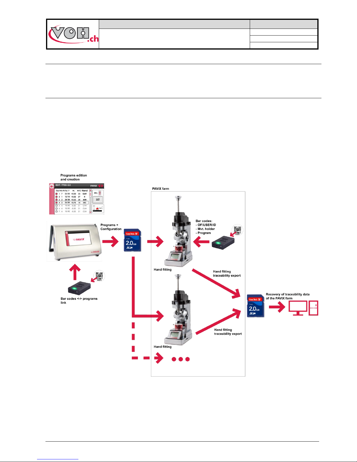
The PAViX is a staking-tool with smart and universal hands. It enhances operator skills while supplying, in a
non-intrusive way, the technical means required for hand-setting operations.
Hand-setting operations are therefore well mastered and traceability of these operations is ensured.
Set out below is the PAViX workflow:
Figure 2: PAViX workflow
Page 6
VOH SA
GU-04-06-01
PAViX - User Guide
Version 3.2
Created 10.2017
Page 6 / 48
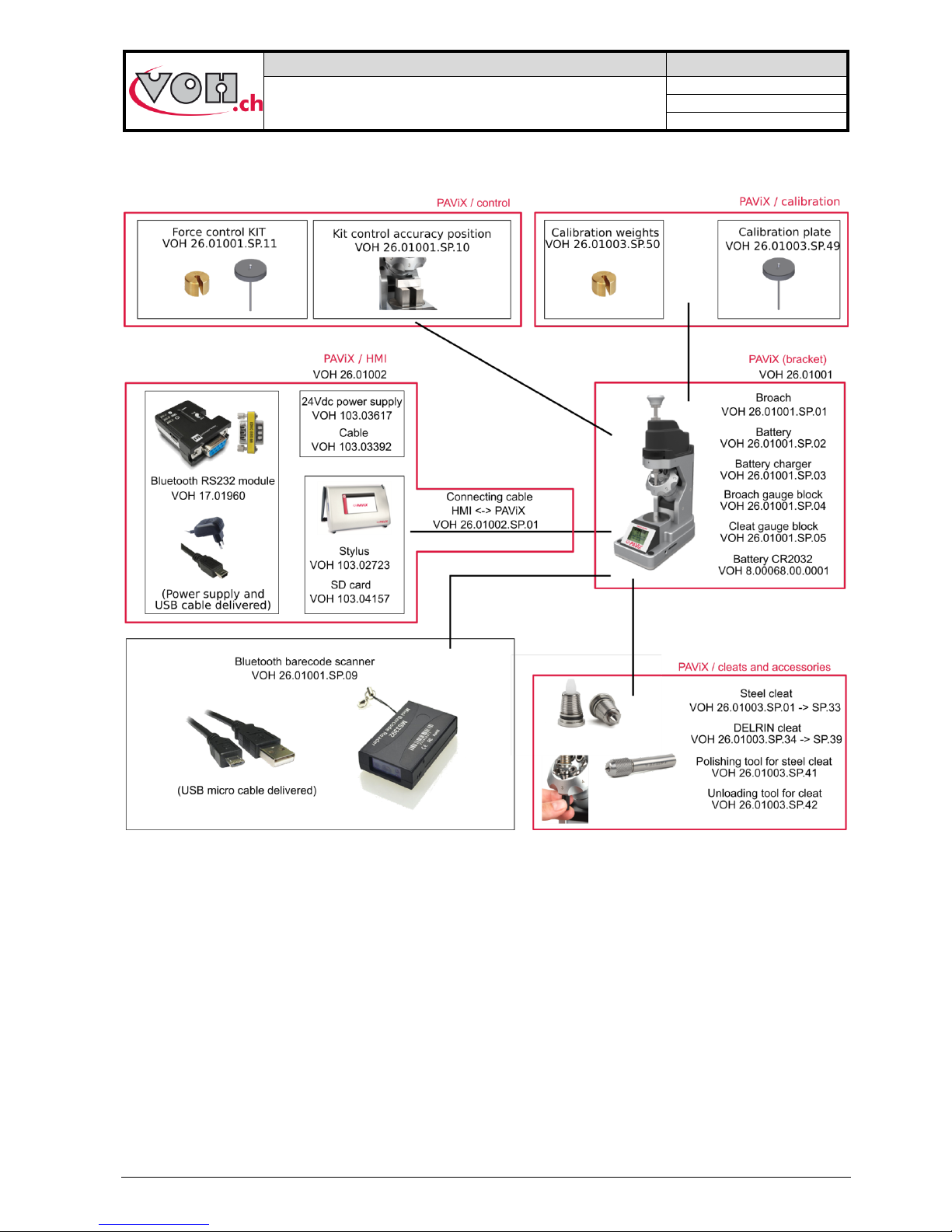
3 Content, accessories and options
Figure 3: PAViX and accessories
Page 7
VOH SA
GU-04-06-01
PAViX - User Guide
Version 3.2
Created 10.2017
Page 7 / 48
4 PAViX – HMI
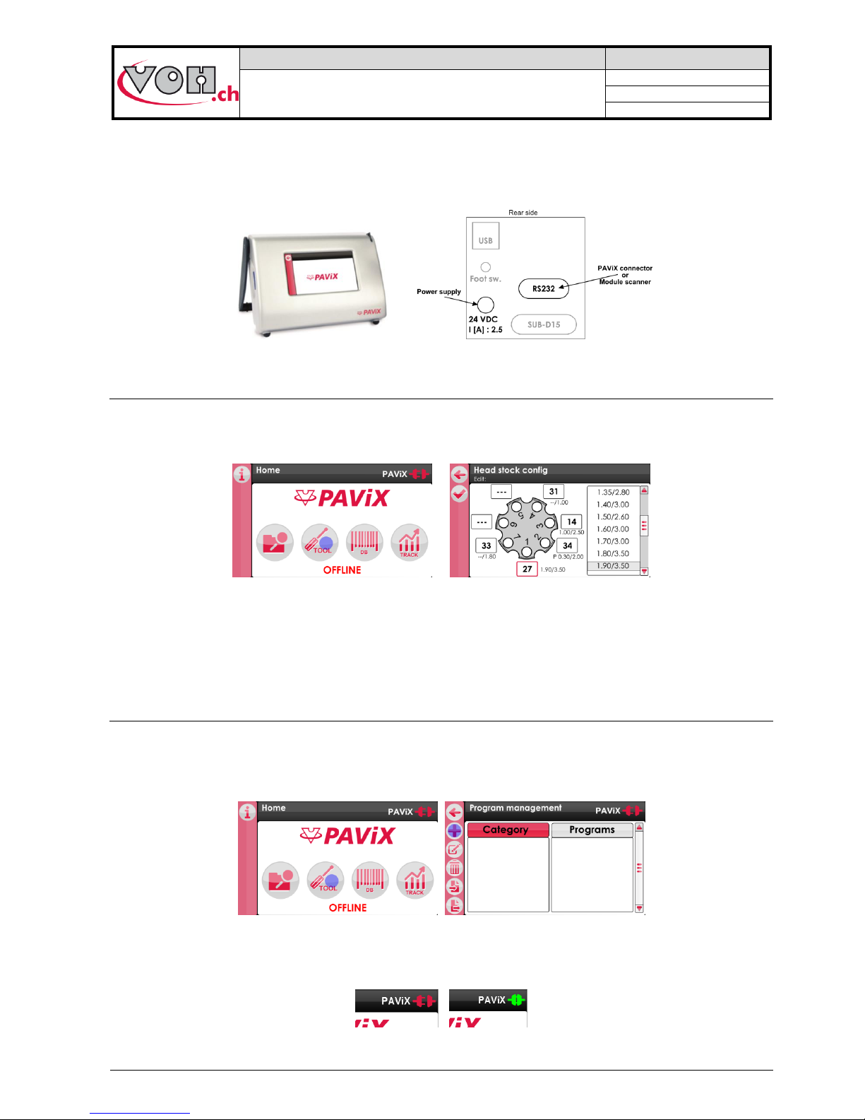
The generation, edition and management of PAViX programs is conducted via an HMI. A unique HMI screen
allows for the management of an unlimited number of PAViXs.
Figure 4: HMI and connectors
4.1 Barrel configuration
The programs use a common barrel configuration. It is managed from the PAViX HMI that is then automatically
transferred to the SD card when the programs are exported.
Figure 5: Barrel configuration management
In order to change the numbers of the cleats present on the barrel, simply click on the fields located around
them then link a standard cleat by clicking in the list located on the right-hand side of the screen.
To “remove” a cleat, simply double-click on the corresponding field. The number then becomes ‘---‘ meaning: no
cleat mounted in this position of the barrel.
4.2 Generation and creation of hand-setting programs
Program management and creation is conducted via the PAViX HMI. The transfer of programs on the PAViX
staking-tool is performed with an SD card.
Hand-setting programs are classified by family then by program.
Figure 6: Home screen and program management
In order to create programs, the PAViX may or may not be connected to the HMI using the supplied cable. La
status of the staking-tool <-> HMI connection is displayed on the top right-hand corner of the screen.
Figure 7: Unconnected staking-tool / Connected staking-tool
Page 8
VOH SA
GU-04-06-01
PAViX - User Guide
Version 3.2
Created 10.2017
Page 8 / 48
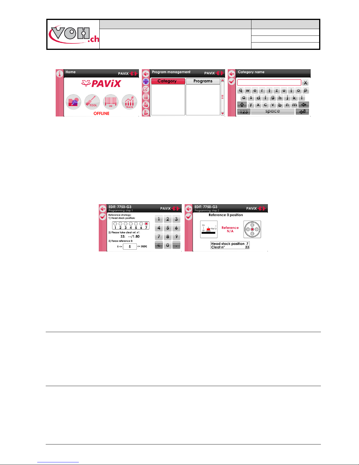
4.2.1 Entering family names and programs
On the home screen, select the navigation icon then press the "+" icon in the left column.
Figure 8: Home screen with navigation icon / Home screen with “+” icon / Creating a calibre
4.2.2 Recording a working reference
It is required, for each created program, to define a height reference for the part-holder movement assembly.
This reference is done using a defined cleat.
The user defines a point on the part-holder that will be used for the reference as well as the height. It is
recommended to set this reference on the hour hand’s hour-wheel or on the minute-wheel.
The user selects the tool position. The cleat number is automatically populated, on the basis of the information
entered in the barrel configuration.
In order to compensate a potential flexion in the movement, the strength of reference “0” can be set to 5 - 20 N.
Figure 9: Selecting the parameters to record the working-program reference
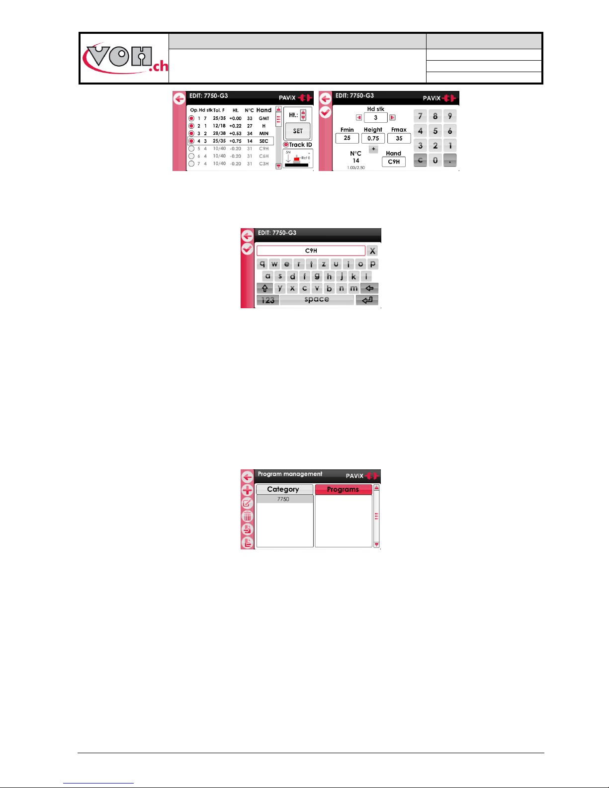
4.2.3 Editing the program
Once the working reference is recorded, the user can enable the stages of the sequence required to set the
hands. A program allows for the setting of up to 14 different hands. Each stage has the following settings:
- Tolerance of min and max force (mandatory)
- Stop height (mandatory)
- Barrel position (mandatory)
- Type of hands set (optional)
4.2.3.1 Programming by learning (ONLINE mode)
Height teaching is carried out with the wheel stop. The height is displayed in real-time and saved using the
“SET” button. To change force, cleat no. and hand type settings, simply select the field concerned.
NOTE: To adjust the height, the position of the barrel on the staking-tool must match that of the selected
operation. If the position of the barrel does not match that of the selected operation, the height is displayed in
red and cannot be changed.
4.2.3.2 Programming by theoretical values (OFFLINE mode)
Height values are determined on the basis of a plan and are manually entered on the hand’s detail page.
Note: All height values can be changed OFFLINE by 0.01mm increments and saved.
Page 9
VOH SA
GU-04-06-01
PAViX - User Guide
Version 3.2
Created 10.2017
Page 9 / 48
Figure 10: Editing the program
To enter the hand type, simply click on the corresponding field to access the page below. A hand name can
have a maximum of 4 characters.
Figure 11: Entering a hand name
4.2.4 Edition of hand-setting programs
Once the programs are developed, simply double click on a program to start its edition. The edition process can
be performed with or without a connected staking-tool.
4.2.5 Authorisation to correct hand fitting heights
Once the programs are created on the HMI, it is generally no longer necessary to correct hand fitting heights
when using the staking-tool.
However, it is possible for the operator to authorise a temporary height correction: simply activate the “Ht
correction” radio button on the Family/Program page:
Figure 12: Height correction
Use of the option to correct heights when carrying out hand fitting operations is detailed here: spindle (refer to: §
5.6.4 Spindle reference, page 23).
Page 10
VOH SA
GU-04-06-01
PAViX - User Guide
Version 3.2
Created 10.2017
Page 10 / 48
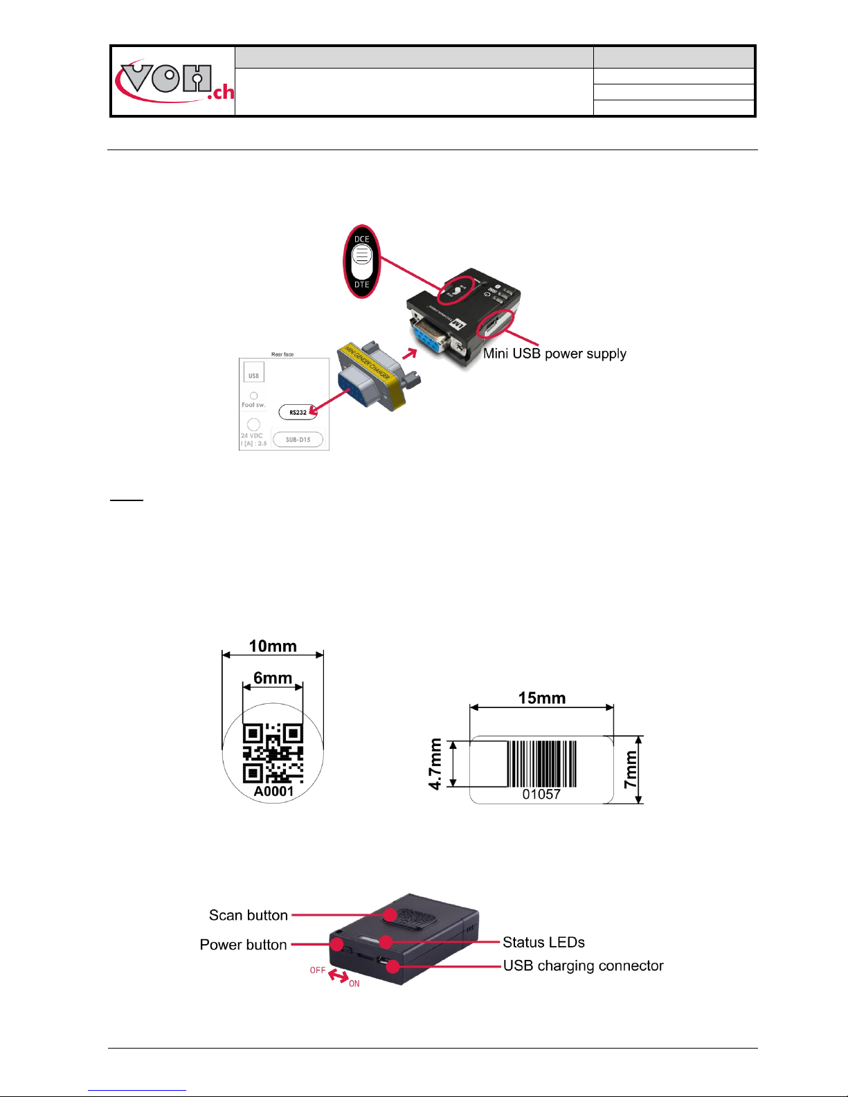
4.3 Management of the bar code database
4.3.1 Bluetooth interface for HMI
This optional interface allows direct communication between the scanner and the HMI. We recommend using a
dedicated scanner (to use with the HMI) in order to facilitate the work (VOH Scanner 26.01001.SP.09)
Figure 13: Adapter assembly
Note:
- In order to work, the Bluetooth interface for HMI must be powered with the supplied USB power supply.
- The small white button on the “LM” module must be placed on the “DCE” side
4.3.2 Bar codes or QR code
Below can be found the minimum dimensions in order for the QR codes (ISO 18004) and bar codes (Code 128)
to be readable by the PAViX Scanner:
Figure 14: Bar code and QR code dimensions
4.3.3 Scanner
The 1D/2D VOH (VOH 26.01001.SP.09) scanner is capable of scanning simple bar codes and QR codes.
Figure 15: VOH Scanner
Page 11
VOH SA
GU-04-06-01
PAViX - User Guide
Version 3.2
Created 10.2017
Page 11 / 48
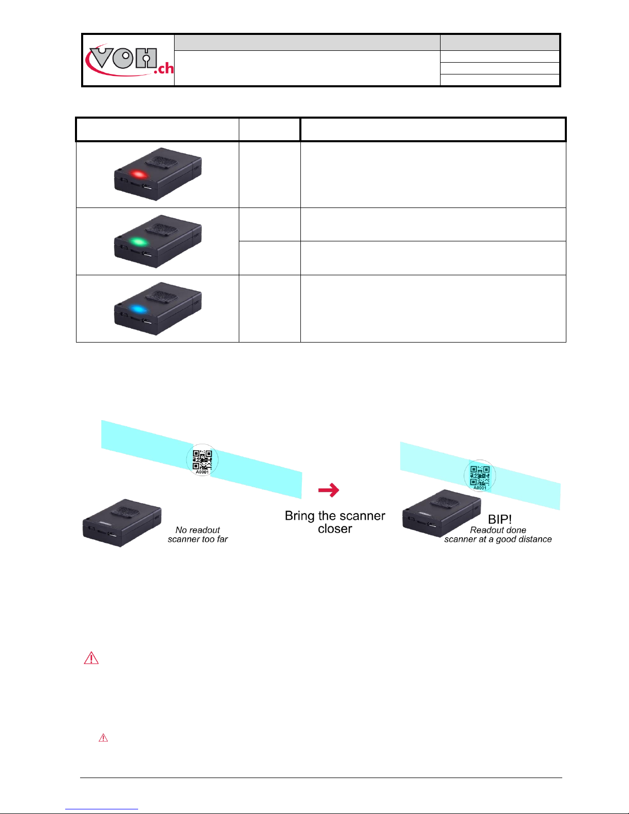
Scanner statuses:
Status LED
Status
Comment
Continuous
Charging (button on the ON or OFF position)
Short flash
Press scan button
Long flash
Scan successful
Flashing
Not connected, discoverable
Scanning area:
When pressing the “Scan button”, the scanner projects 2 blue strips.
Figure 16: scan and blue strips
By varying the distance between the scanner and the target, it becomes possible to make both strips overlap in
the centre: in order to read the code, it must be located at the intersection of the 2 strips!
When reading is successful, a “bip” from the scanner can be heard.
To facilitate the scan, start close to the bar code and gently move away until a long “bip” can be heard.
Battery life:
2 hours charging time.
2 days of operation (1 scan per minute) without having been set to “OFF” at night.
Charging the scanner every night is recommended.
Page 12
VOH SA
GU-04-06-01
PAViX - User Guide
Version 3.2
Created 10.2017
Page 12 / 48
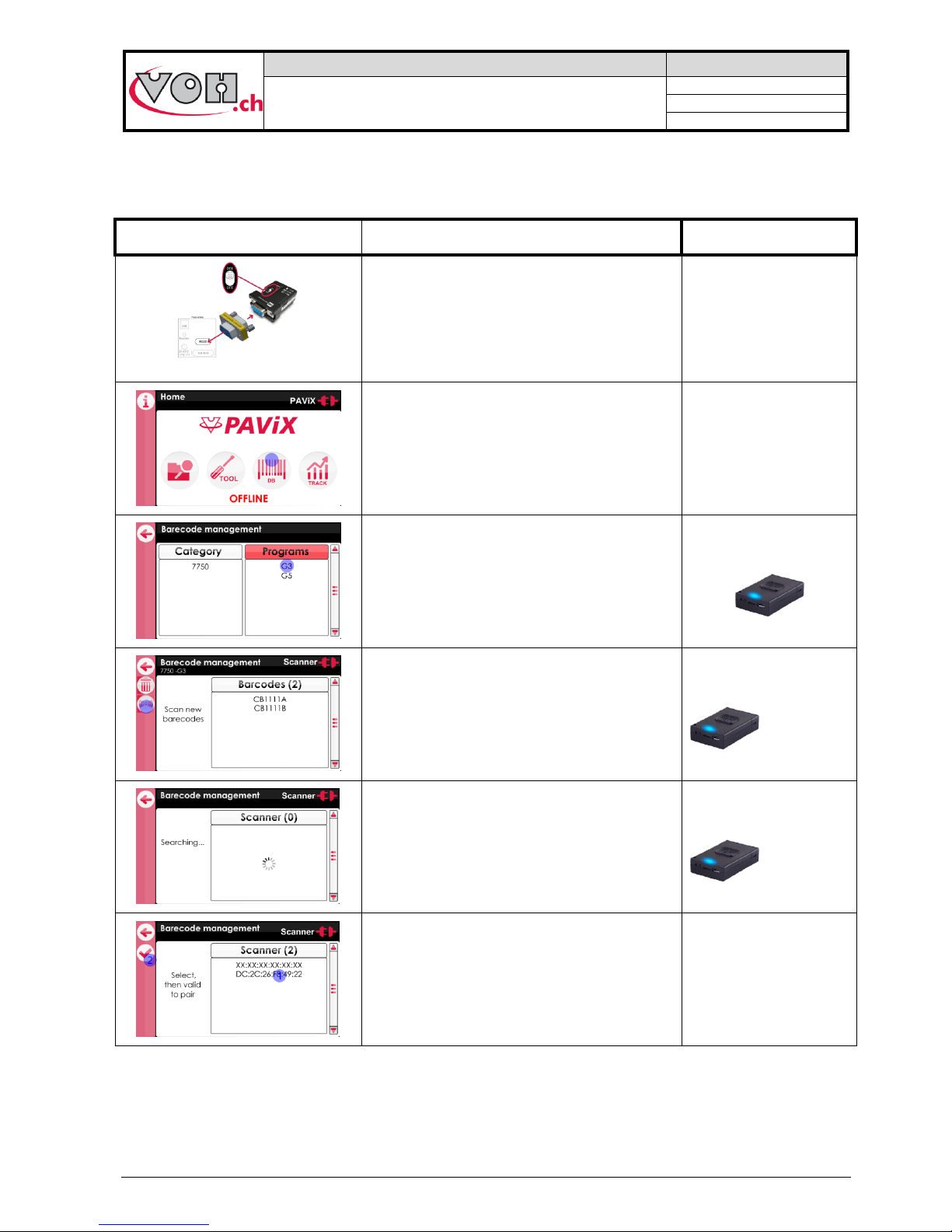
4.3.4 Pairing a scanner to the HIM
Like any other Bluetooth device, the scanner must be paired before use.
PAViX HMI screen
Comment(s)
Scanner + USB power supply
Check for the presence of the Bluetooth
adapter at the back of the PAViX HMI
Power it with the supplied USB power supply
OFF
Click on the “DB” button to access the
bar codes <-> programs linking pages
OFF
Select any program.
The number of bar codes already linked to the
various programs is specified in brackets.
ON
Blue LED flashes
By clicking on the left-hand side button, the
HMI will start searching for a Bluetooth
scanner
ON
Blue LED flashes
The search may take up to 30 seconds.
ON
Blue LED flashes
The list of detected scanners appears.
The selected MAC address (1) must match the
address engraved at the back of the scanner.
Validate the selection (2).
Page 13
VOH SA
GU-04-06-01
PAViX - User Guide
Version 3.2
Created 10.2017
Page 13 / 48
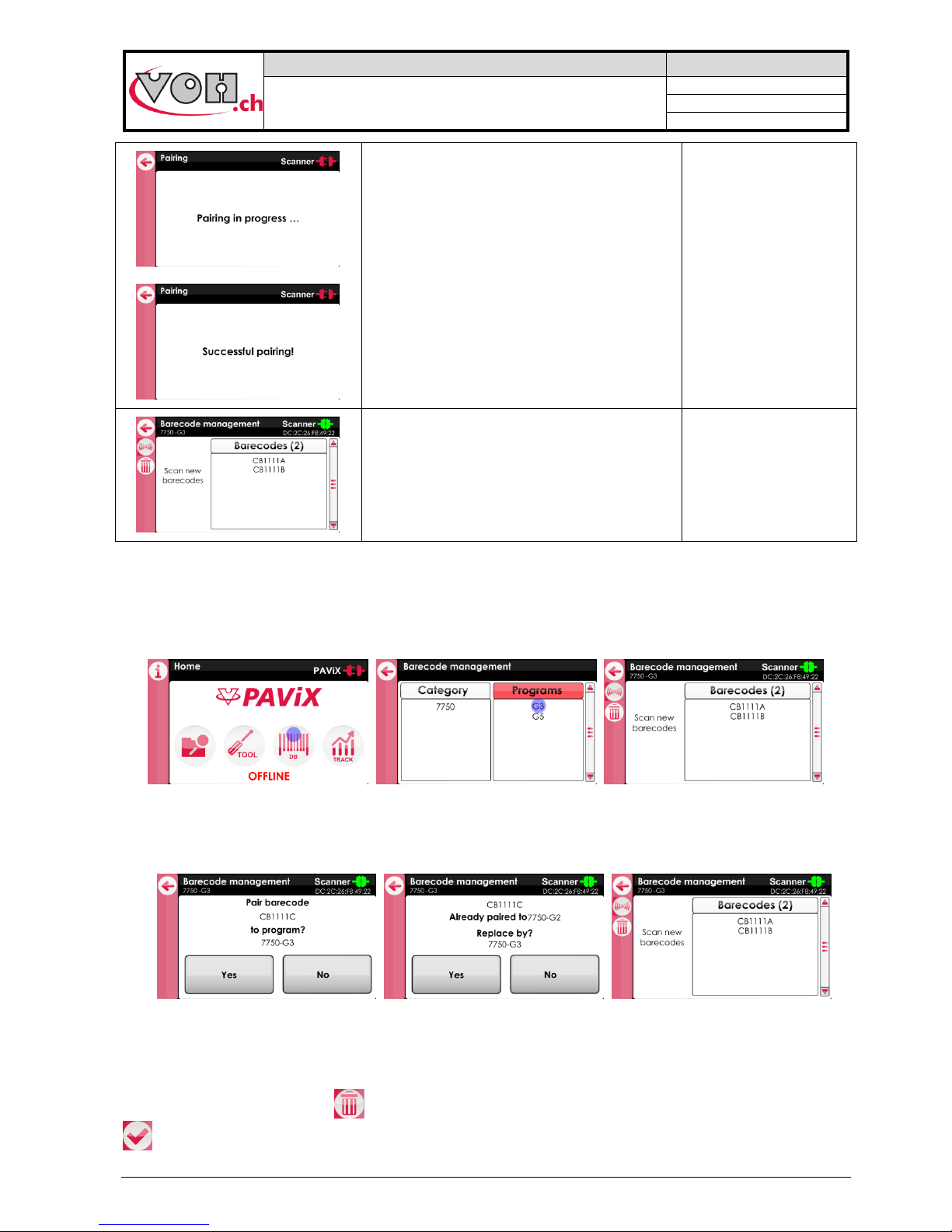
Pairing then proceeds without user action.
Once pairing is
successful, the
scanner’s blue LED
turns off: it is ready to
be used.
The scanner’s connection indicator, on the top
right-hand corner of the screen, then becomes
green.
4.3.5 Bar codes <-> program link
The PAViX automatically calls the programs when scanning bar codes. Several bar codes may be assigned to
the same program (family + program). Management is conducted via the HMI. Press the “DB” button to access
then select the desired program.
Figure 17: Accessing the bar code management section
If it isn’t the case, connect the staking-tool or the scanner’s interface module to the HMI and then scan the bar
code to be assigned to the selected program.
Figure 18: Scanning a bar code
Note: Linking the same bar code to several programs is not possible. A bar code may not contain more than 20
characters, including spaces.
To delete a bar code, press the “ ” after selecting the bar code to delete. Confirm selection by pressing the “
” key.
Page 14
VOH SA
GU-04-06-01
PAViX - User Guide
Version 3.2
Created 10.2017
Page 14 / 48
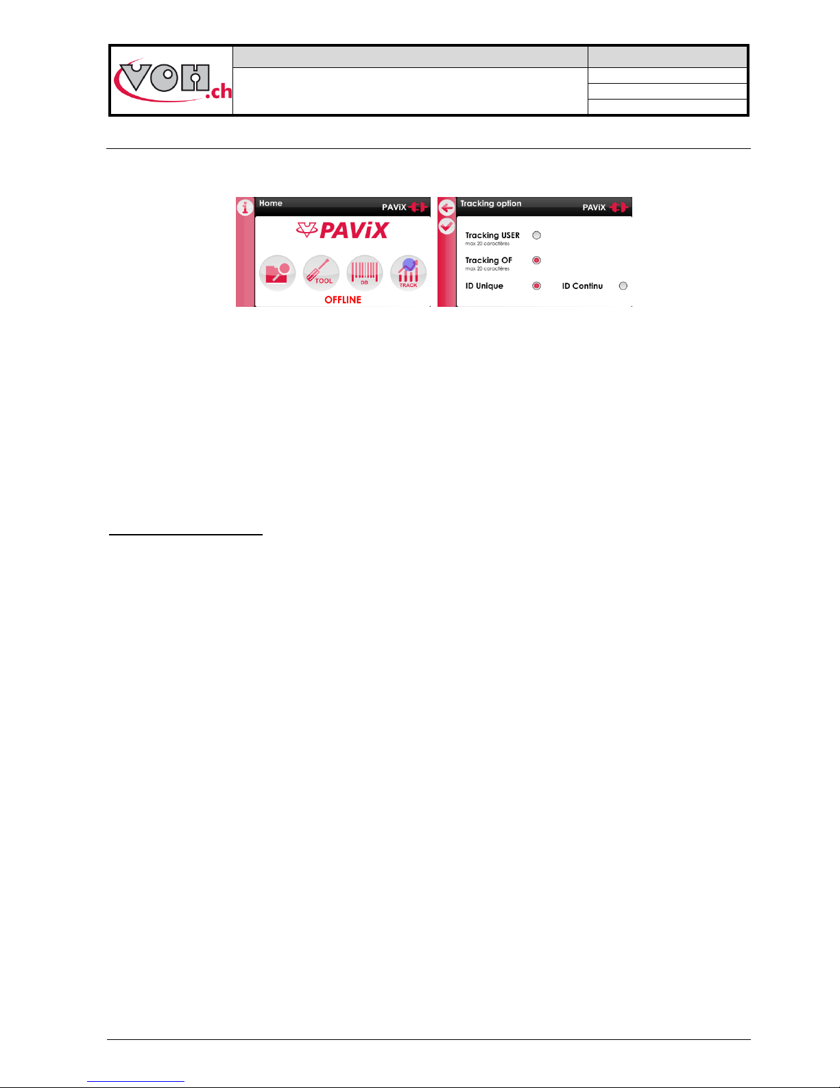
4.4 Strategic management of traceability
The PAViX offers full operation traceability. General traceability options can be configured from the home page
of the PAViX HMI. Press the “TRACK” button to access.
Figure 19: Access to traceability options management
Traceability is based on a bar code or QR code system.
User traceability (USER) is guaranteed for a maximum of 20 characters, its activation being specific to the
staking-tool.
MO traceability is guaranteed for numbers containing up to 20 characters, its activation being specific to the
staking-tool.
Traceability by movement serial numbers is guaranteed for numbers containing up to 10 characters. Activation
of serial number traceability is done in the programs via the “TRACK ID” radio button on the program’s main
page.
Unique or continuous ID:
If « TRACK ID » is activated in the program, it is possible to set a continuous or unique traceability :
- Unique : the ID is requested on each movement (for example: useful for movement traceability)
- Continuous : the ID is kept in memory until a new one is scanned (for example: useful for needle
supplier traceability)
-
These settings are automatically transferred to PAViX staking-tools when updating the hand-setting programs.
Note: These options may be temporarily changed in the staking-tool’s “Traceability” menu.
Page 15
VOH SA
GU-04-06-01
PAViX - User Guide
Version 3.2
Created 10.2017
Page 15 / 48
4.5 Program import / export
When programs are updated/developed, they may be transferred on a SD card using the SD reader located on
the left-hand side of the HMI.
Similarly, programs contained on the SD card may be transferred to an HMI. This operation is carried out using
the Import/Export buttons located in the left column in the program management page.
Figure 20: Import and export commands in the navigation pane
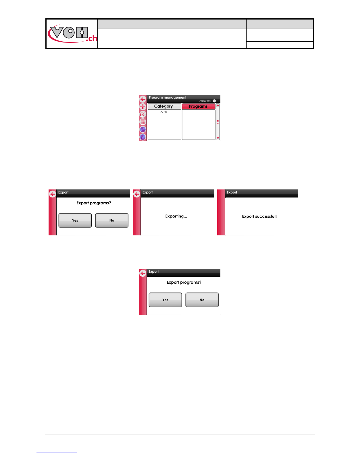
4.5.1 Exporting
After having pressed the “Export” button on the “Program Management” page, confirmation of export is
requested.
Figure 21: Exporting
Exporting program-related bar codes is optional.
Figure 22: Export, question
NOTE (1): barrel configuration is always exported to the external SD card.
NOTE (2): non-initialised programs (listed in red on the “Program Management” page) are not exported.
NOTE (3): any program potentially present of the SD card is deleted. The HIM programs are then exported.
Export ->
Import ->
Page 16

VOH SA
GU-04-06-01
PAViX - User Guide
Version 3.2
Created 10.2017
Page 16 / 48
4.5.2 Importing
Below, the program import procedure from the external SD card.
The families and programs that do not exist in the HIM are created.
Figure 23: Importing
If a program already exists in the HMI, the operator is required to reply to the question below:
Figure 24: Import, question
By clicking on “Yes”, the program present on the SD card replaces the one present on the HMI. The operator
can specify whether he wishes to perform the action (“Yes” or “No”) for all future cases which may arise.
NOTE: When importing, the barrel configuration is always imported from the external SD card.
The SD cards used must be formatted to FAT32, allocation unit size 1024 for full formatting.
Page 17

VOH SA
GU-04-06-01
PAViX - User Guide
Version 3.2
Created 10.2017
Page 17 / 48
4.6 Software update
If a software update is available, the administrator will receive an e-mail from VOH SA containing a ZIP file
called “PAViX_HMI_vx_xx”. In order to update the HMI, open the ZIP file containing a folder called “BL”. Move
this folder to an empty SD card then insert this SD card to the HMI (turned off). The update starts when the HMI
is turned on.
Figure 25: HMI software update
Caution: Do turn off or remove the SD card during the update!
Once the update complete, the HMI automatically displays the home screen.
Caution: After the update is successfully completed, restart the HMI.
Various error screens may be displayed:
PAViX screen
Comment(s)
The HMI is not programmed, please insert a
SD card with the corresponding BL folder.
The SD card was removed during the
programming process. Replace the card in its
holder.
The program contained on the SD card is not
valid. Copy the appropriate program to the SD
card.
NOTE (1): If the SD card contains the same version as the one already present on the HMI, no message shall
be displayed and the HMI will start normally.
Page 18

VOH SA
GU-04-06-01
PAViX - User Guide
Version 3.2
Created 10.2017
Page 18 / 48
5 PAViX - staking-tool
The PAViX is equipped with all the technology required to master the setting of hands. It has an adjustable stop
driven by a motor, a force sensor and a cleat selection system.
Figure 26: PAViX
5.1 Cleat loading / changing
The PAViX is equipped with a barrel that can accommodate up to 7 cleats.
Figure 27: Cleat properly positioned in the barrel, position no. 1 / cleat
NOTE: Be careful not to soil the end of the cleats when handling them so as to avoid transferring dirt to set
hands.
Page 19

VOH SA
GU-04-06-01
PAViX - User Guide
Version 3.2
Created 10.2017
Page 19 / 48
5.2 Battery change and recharging
The PAViX is powered by a battery accessible from the back of the staking-tool. It may be removed using the
opening located under the device.
Batteries are charged in a dedicated charger.
Figure 28: Battery and charger / Changing the battery
5.3 Battery change (CR2032)
The PAViX is equipped with a sensor that measures the height of the stop. This sensor is powered by a
CR2032 battery located at the back of the staking-tool. To change this battery, simply remove its holder by
unscrewing both its retainer screws.
Figure 29: CR2032 battery holder
NOTE: After having replaced the battery, recording the spindle reference again is required, as per the procedure
set out in § 5.6.4 Spindle reference, page 23.
Note: The lifespan of a CR2032 battery is of approximately 1 year.
5.4 PAViX LCD
The PAViX is equipped with a LCD screen where information relating to ongoing operations is displayed. The
screen’s different sections are used as follows:
Figure 30: PAViX LCD information sections
Page 20

VOH SA
GU-04-06-01
PAViX - User Guide
Version 3.2
Created 10.2017
Page 20 / 48
There are two types of buttons for the left and right sections: simple or double buttons. The bar located under
the button’s icon means the length of pressure required to perform the function: a short impulse for the short
bar, a 1.5 second pressure for the long bar:
Figure 31: Simple button (right) and double button (left). To enable the “PAViX settings” function, press and hold down the button
The following buttons and icons are used on the PAViX display
Buttons
Description
Validation
Back to the previous page
ON / OFF
“Guest” identification
“Expert” identification
Manual program selection
Height change
Back to the previous
operation
Exit the program
Back
Edition of part-holder
reference
Icons
Description
Barrel selection
PAViX settings
Height
Height difference
Bluetooth
Battery
Program updates
Traceability DATA export
PAViX memory eraser
SD card
Current operation
Memory usage (here ¼
still available)
Page 21

VOH SA
GU-04-06-01
PAViX - User Guide
Version 3.2
Created 10.2017
Page 21 / 48
5.5 Start up
Before starting the PAViX, ensure a properly charged battery is in place in the holder located at the rear of the
staking-tool.
To start the PAViX, simply press and hold the button located on the right-hand side of the LCD screen.
Figure 32: Starting the PAViX - press and hold the right-hand side button
5.6 Configuration of PAViX settings
PAViX basic settings are accessible through the “settings” icon during startup of the staking-tool.
Figure 33: PAViX - “settings” icon to the left
Navigation in the “settings” menu is done with the barrel.
Figure 34: PAViX configuration menus
The icon located at the bottom centre of the screen represents the barrel function.
Page 22

VOH SA
GU-04-06-01
PAViX - User Guide
Version 3.2
Created 10.2017
Page 22 / 48
5.6.1 Barrel configuration
The system uses a barrel configuration common to all programs. This configuration can be displayed from the
barrel configuration menu. Furthermore, when this menu is displayed, the PAViX motorised stop places itself in
the upper position so as to facilitate the loading/unloading of cleats.
Figure 35: Barrel configuration
5.6.2 Recording cleat references
The height of the cleats present in the barrel may vary (replacement or polishing of a cleat). It is therefore
necessary to save these heights by teaching.
NOTE: Cleat references cannot be recorded before the spindle reference (refer to § 5.6.4 Spindle reference,
page 23).
PAViX screen
Comment(s)
PAViX
Teaching of cleat heights is done from the cleat
references menu
Select the barrel position for which a cleat reference is
required.
Once selection is made, the staking-tool will move the
stop to the low position.
Place the standard cleat (PAViX ET) on the plate.
Height reference is taken using a given force, which is
why the staking-tool tares the force before height
reference is performed (please do not touch the tray
during this phase).
Press the spindle down so the cleat comes into contact
with the movement and the light turns green (meaning the
force has been reached). When it is green for >2s, the
PAViX records the reference.
Page 23

VOH SA
GU-04-06-01
PAViX - User Guide
Version 3.2
Created 10.2017
Page 23 / 48
The user must hold the spindle in position while the
reference is being recorded.
NOTE: If the force becomes too great or too weak when
the reference is being recorded, the process is
interrupted.
Once the reference is recorded, the user can release the
spindle. A check mark appears under the barrel position
for which reference was taken.
Repeat the above operations for each cleat.
If one barrel position is not used, the display will indicate it
as void.
It is crucial to perform the operation on all active positions
5.6.3 Time/Date
The PAViX offers extended traceability options. For these to be relevant, it is required to set the time on the
PAViX clock. This setting is done from the “Time/Date” menu. The selected field is underlined. To change its
value, use the barrel and validate with the right-hand side button.
Figure 36: Setting the time and date
5.6.4 Spindle reference
The PAViX is equipped with an absolute height measuring system. This system is powered by a CR2032
battery located at the back of the staking-tool. When the battery voltage drops below the operational threshold,
the PAViX notifies the user for him/her to replace it.
Figure 37: Low battery warning and battery housing for the height measuring function (CR2032)
Page 24

VOH SA
GU-04-06-01
PAViX - User Guide
Version 3.2
Created 10.2017
Page 24 / 48
Once the battery has been replaced, the PAViX requires a height reference record. This height reference must
be carried out with the standard spindle. The procedure to apply is as follows.
PAViX screen
Comment(s)
PAViX
After the CR2032 battery has been replaced, the PAViX
cannot be used until the height reference has been
recorded
Remove a cleat or place an empty barrel slot under the
spindle. Place the standard spindle on the plate (PAViX
EB)
Manually lower the stop using the wheel and validate
when this operation is complete
Press the spindle down so the cleat comes into contact
with the movement and the light turns green (meaning the
force has been reached). When it is green for >2s, the
PAViX records the reference.
The user must hold the spindle in position while the
reference is being recorded.
NOTE: If the force becomes too great or too weak when
the reference is being recorded, the process is
interrupted.
Reference recorded.
Page 25

VOH SA
GU-04-06-01
PAViX - User Guide
Version 3.2
Created 10.2017
Page 25 / 48
5.6.5 User type change
The PAViX manages two types of users: Operator and Locked.
In Operator mode, the user can correct hand fitting heights. In Locked mode, this operation is not possible.
Figure 38: User mode selection
“Operator” mode is the same as the checked “Ht correction” radio button in the HIM (refer to § 4.2.5
Authorisation to correct hand fitting heights, page 14). A change of user type in the staking-tool overwrites the
setting selected when creating the programs in the HMI.
5.6.6 Buzzer
The PAViX provides a sound signal option during operations. These signals are configured from the “Buzzer”
menu.
Figure 39: Sound signals on force(a) / on stop(b)
Depending on the selected settings, a sound is released:
- When the min force is reached and when the maximum force is exceeded
- When the maximum force is exceeded
- When the stop is reached
5.6.7 LED
The PAViX also provides the option to indicate the hand fitting status in three different colours: orange if the
force is below tolerance, green if the force is within the tolerance range and red if the maximum force is
exceeded.
The intensity of these light signals can be configured from the “LED” menu. It is possible to configure the
intensity or disable the signal with the barrel.
Figure 40: Light intensity adjustment
5.6.8 Screen contrast
The PAViX provides the option to adjust the screen’s contrast so as to adapt to various light environments.
Figure 41: Screen contrast adjustment
Page 26

VOH SA
GU-04-06-01
PAViX - User Guide
Version 3.2
Created 10.2017
Page 26 / 48
5.6.9 Sleep timer
As the PAViX is self-sufficient in energy, a timer enables the Standby mode when the device is not being used.
This timer can be set from the “Sleep timer” menu to: 10 minutes, 30 minutes or Disabled (no automatic
activation of the Standby mode).
Figure 42: Setting the time before standby
5.6.10 Bluetooth
The PAViX is equipped with a Bluetooth function. It can be configured so as to be used in different ways:
- Off
- Used with a scanner
- Used with a PC/tablet.
Figure 43: Bluetooth adjustment options
5.6.11 Use of a bar code reader (Bluetooth scanner)
If the user wishes to use a bar code scanner, he/she must first connect it to the PAViX. This operation can be
done using the “Scanner” menu.
Before starting the staking-tool, ensure the scanner is in Bluetooth® SPP mode. To this end, start the scanner
using the switch located at the back and scan the bar codes below in order (that can also be found on the user
guide supplied with the scanner)
Figure 44: Bar code for SPP mode configuration
Page 27

VOH SA
GU-04-06-01
PAViX - User Guide
Version 3.2
Created 10.2017
Page 27 / 48
Once the scanner is in SPP mode, it flashes blue for as long as it is not connected to the staking-tool. The
procedure described below can then be performed. Once the scanner is connected and switched on, the
staking-tool automatically detects its presence at less than 1m away.
PAViX screen
Comment(s)
When the “Scanner” menu is selected, the
PAViX performs a search of the scanners in its
range. The scanners are then classified
depending on their distance to the PAViX.
NOTE: If no scanner is detected, an error
message is displayed.
The user then selects the scanner’s
corresponding MAC address he/she wishes to
pair up.
The PAViX then establishes the connection
with the scanner and informs the user on the
outcome of the operation (success or not).
NOTE: The scanner emits a sound when the
connection is established.
The PAViX can only pair with one bar code reader (Item no.: 26.01001.SP.09).
Figure 45: Bluetooth scanner (Item no.: 26.01001.SP.09)
Scanner operation: § 4.3.3 Scanner, page 10.
5.6.12 Information
The Information menu displays all the information relating to the staking-tool:
- Staking-tool SN
- Staking-tool software version
- Force sensor SN
Page 28

VOH SA
GU-04-06-01
PAViX - User Guide
Version 3.2
Created 10.2017
Page 28 / 48
5.6.13 Language
The PAViX provides the option to select the language from the “Language” menu.
Figure 46: Configuration of the PAViX language
5.6.14 Traceability
The PAViX offers extended traceability options. Traceability rules are configured from the “Traceability” menu.
Traceability can be enabled on the users (USER), manufacturing orders (MO) and continuous ID traceability by
entering the administrator password (1234). Movement serial number traceability is enabled in each program
(via the PAViX HMI)
Figure 47: Traceability summary
NOTE: Traceability settings can also be managed from the PAViX HMI (Refer to § 4.4 Strategic management of
traceability, page 14).
Note: Continuous ID traceability allows the scanned ID to be stored in the memory when moving to the next
movement (Refer to § 6.3.2 Hand-setting, page 37).
If this setting is disabled (OFF), a new ID scan is requested after each movement.
Page 29

VOH SA
GU-04-06-01
PAViX - User Guide
Version 3.2
Created 10.2017
Page 29 / 48
5.7 Program and data management
The PAViX “ADMIN” menu allows for the following actions:
- Recovery of hand fitting results
- Program updates
5.7.1 Access to the ADMIN menu
The Administrator mode (ADMIN) is used to update programs, export results of hand-setting operations saved
by the staking-tool as well as reset the device’s memory. Resetting the memory erases all hand-setting
programs as well as traceability data contained in the device. Access to the Admin mode is done using the
following password: 1234
PAViX screen
Comment(s)
PAViX
The ADMIN menu is accessible via one of the
configuration pages: press and hold the PAViX left-hand
side button to enter the setting mode.
Then, by rotating the barrel to the left, the ADMIN menu
will appear.
Confirm access with the right-hand side button.
The barrel allows the user to select the number to display,
the right-hand side button is used to confirm the choice.
See below for use of the ADMIN mode.
Page 30

VOH SA
GU-04-06-01
PAViX - User Guide
Version 3.2
Created 10.2017
Page 30 / 48
5.7.2 Program updates
The programs contain the fitting parameters required for hand setting operations.
In order to use the PAViX, it must contain hand-setting programs that are transferred using a SD card according
to the following procedure:
PAViX screen
Comment(s)
PAViX
To transfer programs, insert the SD card and select .
NOTE: When updating, the information contained on the
SD card has priority
When the user validates the action with the right-hand
side button, the programs contained in the device’s
memory are updated and hand fitting data is automatically
transferred to the SD card.
The PAViX memory can contain up to 1,000 programs. The PAViX memory can be erased using the Trash icon
from the ADMIN menu. When updating the programs, movement holder height references are erased.
The SD cards used must be formatted to FAT32, allocation unit size 1024 for full formatting.
5.7.3 Recovery of hand fitting results
The PAViX is equipped with a system that traces hand-setting operations. The PAViX can store up to 9,000
operations.
We therefore recommend saving the device’s memory on a regular basis. Data export is carried out as follows:
PAViX screen
Comment(s)
PAViX
To retrieve stored data, insert the SD card and select (
).
NOTE: The data stored in the PAViX memory is erased
after the transfer.
Page 31

VOH SA
GU-04-06-01
PAViX - User Guide
Version 3.2
Created 10.2017
Page 31 / 48
When the user validates the action with the right-hand
side button, the data contained in the device’s memory is
transferred to the SD card.
- The results are exported in a “.csv” format that can be opened in an Excel-type spreadsheet.
- Results are sorted by staking-tool and by program
- If a program is already present, data is added at the end of the file
Below is an overview of a PAViX export opened on a Windows PC:
Figure 48: SD on PC and SD tree structure
Figure 49: Example of a .csv file content exported from the PAViX
Page 32

VOH SA
GU-04-06-01
PAViX - User Guide
Version 3.2
Created 10.2017
Page 32 / 48
5.8 Software update
If an update is available, the administrator will receive an e-mail from VOH SA containing a ZIP file called
“PAViX_potence_vx_xx”. In order to update the staking-tool, open the ZIP file containing a folder called “BL”.
Move this folder to an empty SD card then insert this SD card to the staking-tool (turned off). The update starts
when the staking-tool is turned on.
Figure 50: Staking-tool software version
Do turn off or remove the SD card during programming!
Once the update complete, the PAViX automatically displays the home screen.
Various error screens may be displayed:
PAViX screen
Comment(s)
PAViX
The staking-tool is not programmed, please
insert a SD card with the corresponding BL
folder
The SD card was removed during the
programming process. Replace the card in its
holder.
The battery is not sufficient to program the
staking-tool. Replace the battery
The program contained on the SD card is not
valid. Copy the appropriate program to the SD
card.
Page 33

VOH SA
GU-04-06-01
PAViX - User Guide
Version 3.2
Created 10.2017
Page 33 / 48
6 Hand-setting
In order to have all the information required for traceability purposes, the user may be required to scan a certain
number of information before starting hand-setting operations.
6.1 User identification
When starting the PAViX, the user is prompted to identify from the home screen. Identification is carried out with
the bar code scanner.
Figure 51: Home screen without a scanner then in User or Expert mode with a connected scanner
The graph located above the “ON/OFF” icon ( ) represents the memory used by the traceability data. The
graph is divided into 8 sections. Each section therefore equates to 12.5% of the total memory. When traceability
data occupies less than 12.5% of the total memory, the graph is empty ( ). When the staking-tool is used and
the traceability data is stored, the graph gradually fills out. When the memory is full ( ), the oldest data is
replaced by the newest data.
NOTE: Users can identify themselves as guests using the right-hand side button ( / ). In this case, user
traceability will be replaced by “GUEST”.
6.2 Selection of the hand-setting program
Starting a hand-setting program can be done two different ways.
- Manual selection
- Automatic selection by bar code (when the scanner is connected)
6.2.1 Manual selection
When manually selecting the corresponding program, the user uses the barrel and the buttons to perform the
selection.
PAViX screen
Comment(s)
After identifying himself/herself, the user
presses the right-hand side button ( ) to
enable the manual selection of a program.
The family is then selected using the barrel
and validated with the right-hand side button.
The left-hand side button takes you back to the
previous page.
The program is then selected using the same
method.
Page 34

VOH SA
GU-04-06-01
PAViX - User Guide
Version 3.2
Created 10.2017
Page 34 / 48
6.2.2 Automatic loading of the bar code program
For automatic selection by bar code, the user uses the bar code scanner to select a program.
The link between a bar code and a program is done in the PAViX HMI (Refer to § 4.3 Management of the bar
code database, page 10).
PAViX screen
Comment(s)
After identifying himself/herself, the user scans
a bar code corresponding to the program
he/she wishes to call.
NOTE: The bar code can contain up to 20
characters maximum.
NOTE: If the bar code read by the scanner matches a program, the program is automatically called.
Page 35

VOH SA
GU-04-06-01
PAViX - User Guide
Version 3.2
Created 10.2017
Page 35 / 48
6.3 Performing a hand-setting operation
When the program is selected (via a scanned bar code or a manual selection from the list of programs), the
system needs to know the movement holder height before starting a hand-setting program.
The system will request taking of this “0” reference each time a program starts or will offer to scan a bar code
present on the movement holder.
6.3.1.1 Taking a reference without an active scanner
PAViX screen
Comment(s)
When the program has started and no scanner
is active, the user is invited to use the 0
reference.
Start by placing the part-holder, then validate
with the button located on the right-hand side
of the staking-tool.
Select the requested barrel position, here no.1.
Confirm selection with the right-hand side
button
The system automatically tares the force once
placement of the movement holder is
validated.
Press the spindle down so the cleat comes into
contact with the movement and the light turns
green (meaning the force has been reached).
When it is green for >2s, the PAViX records
the reference.
Page 36

VOH SA
GU-04-06-01
PAViX - User Guide
Version 3.2
Created 10.2017
Page 36 / 48
6.3.1.2 Taking movement holder reference with the scanner
Using the bar code reader streamlines taking of reference 0. The PAViX provides the option to store the heights
of the part-holder so as to avoid recording this reference when starting the program. To do this, the part-holders
must have bar codes. Starting a program is then done as follows.
PAViX screen
Comment(s)
Once the program is started, the user is
prompted to:
1) Record the reference in accordance
with standard procedure (Refer to
6.3.1.1, page 35)
2) Scan a part-holder bar code
NOTE: If the bar code is known, the PAViX
places itself directly in Hand-setting mode.
By pressing and holding the left-hand side
button, it is possible to change the height of a
part-holder whose bar code is already known.
Once the button is pressed down, simply follow
the information on the screen.
If the bar code of the scanned part-holder is
not known, the user is prompted to create a
new part-holder. To do this, simply press the
right-hand side button.
The PAViX then guides the user through the
standard reference recording procedure
Once the reference is recorded, simply
validate for the part-holder to be stored and for
the program to start
NOTE: Part-holder bar codes must contain 5 characters (alphanumeric).
Page 37

VOH SA
GU-04-06-01
PAViX - User Guide
Version 3.2
Created 10.2017
Page 37 / 48
6.3.2 Hand-setting
When selecting a program, if the staking-tool is not connected to a scanner, the user is prompted to record the
working reference in accordance with the procedure presented in Paragraph 4.2.2 , page 35. Once the
reference is recorded, the hand-setting program can start.
Figure 52: Hand-setting screen
Figure 53: Hand-setting screen (barrel position turns black when it matches the one defined in the program)
Figure 54: Hand fitting result screen
When the user selects an active cleat (by turning the barrel), the PAViX automatically adjusts the stop height as
well as the information displayed on the screen. During the adjustment of the height, the luminous surface
flashes blue.
Figure 55: Flashing luminous surface during height adjustment and other automatic operations
The user performs the hand fitting operation by lowering the spindle that, when passing through the barrel,
takes the selected cleat. During the operation, light and sound signals indicate the change in force.
Figure 56: Force change indication during the hand-setting operation
Page 38

VOH SA
GU-04-06-01
PAViX - User Guide
Version 3.2
Created 10.2017
Page 38 / 48
The operator is guided by the PAViX during the hand-setting operations, as shown in the diagram below.
PAViX screen
Comment(s)
If ID traceability is enabled and a scanner is
connected, the PAViX prompts the operator to
enter a movement identification bar code.
At the start of the program, the PAViX prompts
the operator to select the required barrel
position (position 7)
Once the position is selected, the number 7
goes to a black box and the staking-tool moves
to the appropriate height. The operator can
then place the hand
When the hand fitting operation is complete, its
result is displayed. Of everything is OK, the
result is automatically validated after 3
seconds and the following instruction is
displayed.
In the event of a KO, the operator will need to
validate the operation with the right-hand side
button, then a simple short impulse on the lefthand side button will repeat the operation with
a compliant hand.
The PAViX then prompts the operator to move
to barrel position no.1 in order to mount the
next hand
Once the position is selected, the number 1
goes to a black box and so forth until the end
of the program
After the last hand fitting operation (barrel
position no.3 in the program opposite), the
operator may move to the next movement
(right-hand side button) or start a new MO by
exiting the program (left-hand side button)
Page 39

VOH SA
GU-04-06-01
PAViX - User Guide
Version 3.2
Created 10.2017
Page 39 / 48
6.3.3 Hand-setting operation results
The PAViX is used to carry out hand-setting operations on an industrial scale. Productivity is critical while
maintaining operation traceability and control.
The result of a hand-setting operation is determined based on the force applied to the hand when the spindle
comes into contact with the stop. The force saved for traceability purposes is the force measured at the moment
the stop comes into contact with the spindle.
Figure 57: Indication of the result (force at stop contact within the tolerance range, without exceeding the max. tolerance)
The following situations may also occur:
Figure 58: KO operation (F > max. tol)
If, during the operation, the max. tolerance is exceeded, the operator is supposed to stop what he/she is doing.
The result of the operation is then KO (F > max. tol and stop not reached). The light signal is fixed red. If the
operator continues to the stop, the result will be considered KO and the force saved for traceability purposes
shall be the maximum force observed during the operation.
Figure 59: KO operation (F < min. tol)
If the force measured when the stop contact is detected is below the min tolerance, the result will be considered
KO. The force saved for traceability purposes is the force measured at the moment the stop comes into contact
with the spindle.
Page 40

VOH SA
GU-04-06-01
PAViX - User Guide
Version 3.2
Created 10.2017
Page 40 / 48
In order to manage cases very close to the upper limit, the PAViX is equipped with an intelligent system that
takes into account human reaction time (0.1s). If the measured force exceeds the max tolerance by less than
10% in a time interval smaller than 0.1s before stop detection, the operation is considered successful.
Furthermore, as the displacement potentially applied during the 0.1s is low, the movement will not be damaged.
The force saved for traceability purposes is the force measured at the moment the stop comes into contact with
the spindle.
Figure 60: Smart detection, OK operation and details
The results for the setting operation are indicated as soon as the stop is reached or the max force is exceeded.
F < Fmin
Fmin<F<=Fmax
F > Fmax
Stop reached
Stop not reached
N/A
N/A
The results in red must be acknowledged by the operator using the right-hand side button. OK operations are
automatically validated after a period of 1.5 seconds.
6.3.4 Height corrections
If the “Ht correction” option has been enabled in the HMI when creating the programs or when the “Operator”
mode is selected in the staking-tool, it is possible to correct hand fitting heights by pressing and holding the
right-hand side button (as long as the current barrel position matches the current operation):
Figure 61: Hand fitting in “Operator” mode (equivalent of the “Ht correction” option of the HMI)
When the button has been pressed and held down, the following page is displayed:
Figure 62: Height correction page
Simply turn the height setting wheel to perform the correction. The correction is displayed on the screen in mm.
Note: Height correction is available in this program on a temporary basis. It is lost when the user leaves the
program.
Page 41

VOH SA
GU-04-06-01
PAViX - User Guide
Version 3.2
Created 10.2017
Page 41 / 48
7 Exclusion of liability/guarantee
Damages caused by conditions of use, transport or storage non-compliant with the conditions described in this
manual are not supported by the manufacturer. Changes to the device and opening of the casing are forbidden
and lead to exclusion of liability. Guarantee rights expire when it is proven that the detected faults are not from
origin.
8 Maintenance and service
8.1 Cleaning of the spindle
Frequency: Once a week (depending on use)
Equipment required:
- Light Benzine
- Clean cloth
Stage
Description
1
Remove the spindle
2
Dampen the cloth with light Benzine
3
Clean the entire length of the spindle
4
Let the spindle dry before putting back into
place
Page 42

VOH SA
GU-04-06-01
PAViX - User Guide
Version 3.2
Created 10.2017
Page 42 / 48
8.2 Cleaning of spindle smooth bearings
Frequency: Once a week (depending on use)
Equipment required:
- Light Benzine
- Cotton buds
Stage
Description
1
Remove the spindle
2
Dampen a cotton bud
3
Clean the upper bearing
4
Clean the lower bearing
5
Let the spindle dry before putting back into
place
8.3 Replacement of the backup battery (CR2032)
Frequency: Once a year (depending on the staking-tool’s signals)
Equipment required:
- CR2032 battery
- Watchmaker's screwdriver - 140
- Spindle height standard
Stage
Description
1
Turn the staking-tool off
2
Remove the main battery
3
Unscrew the two retaining screws of the
CR2032 holder
4
Remove the battery holder
5
Replace the used battery with a new one
6
Insert the battery holder in its housing et
secure using the screws provided for this
purpose
7
Set staking-tool time as described in the user
guider
8
Record a spindle reference as per the user
guide
Page 43

VOH SA
GU-04-06-01
PAViX - User Guide
Version 3.2
Created 10.2017
Page 43 / 48
8.4 Sensor inspection
8.4.1 Access to the Maintenance menu
The Maintenance mode is used to inspect distance and force sensors.
This is done by a validating the force or distance measurement by using a weight or a gauge block. Access to
the Maintenance mode is done using the following password: 7426
PAViX screen
Comment(s)
PAViX
The Maintenance menu is accessible via one of the
configuration pages: press and hold the PAViX left-hand
side button to enter the Setting mode.
Then, by rotating the barrel twice to the left, the
Maintenance menu will appear.
Confirm access using the right-hand side button.
The barrel allows the user to select the number to display,
the right-hand side button is used to confirm the choice.
The barrel is used to select the validation to perform:
- Distance : “Position[um]”
- Force: “Valid[N]”
Page 44

VOH SA
GU-04-06-01
PAViX - User Guide
Version 3.2
Created 10.2017
Page 44 / 48
8.4.2 Verifying force measurement accuracy
Verification of force measurement accuracy requires a quiet environment as well as a rigid and stable work
surface.
Equipment required:
- Force measurement accuracy verification kit VOH 26.01001.SP11
- Standard spindle VOH 26.01001.SP04
Fitting procedure
PAViX screen
Comment(s)
PAViX
Remove the spindle and cleat in position under the
spindle.
To facilitate cleat removal, the spindle automatically
moves to a high position during initialisation.
Start by placing the standard spindle (SP.04 “EB”) on
the plate. Confirm with the right-hand side button.
Then place the calibration plate in place of the spindle,
resting on the standard spindle. Validate using the righthand side button
The PAViX automatically tares the force: do not
touch the calibration plate of the PAViX plate.
Page 45

VOH SA
GU-04-06-01
PAViX - User Guide
Version 3.2
Created 10.2017
Page 45 / 48
Validation procedure:
PAViX screen
Comment(s)
PAViX
…
1) Delicately place the required mass on the plate.
Confirm placement using the right-hand side
button.
2) Once the measurement is stable, confirm using
the right-hand side button.
These 2 operations must be performed with 1, 2 and 5kg
masses.
If the measures are correct, the screen displays “OK”.
Upon the first measure with an out-of-machinetolerance value, the operator is invited to recalibrate
the force.
(Refer to § 8.4.3 Force calibration, page 46)
Page 46

VOH SA
GU-04-06-01
PAViX - User Guide
Version 3.2
Created 10.2017
Page 46 / 48
8.4.3 Force calibration
Force calibration requires a quiet environment as well as a rigid and stable work surface.
Equipment required:
- Calibration plate VOH 26.01003.SP49
- Set of standard weights for calibration VOH 26.01003.SP50
- Standard spindle VOH 26.01001.SP04
Validation procedure:
PAViX screen
Comment(s)
PAViX
If force validation gives an out-of-machine-specification
result, you are prompted to calibrate the force
measurement system.
Remove the spindle and cleat in position under the
spindle.
Then place the calibration plate in place of the spindle,
resting on the standard spindle. Confirm with the righthand side button.
Once the measure is stable, the “check mark” button
appears.
It allows the operator to move to the next step.
Like on the image
below, with no weight.
Repeat the operations opposite for 1, 2, 5 and 10kg
masses.
Once calibration is complete, the error relating to the
extent of measurement is displayed (<= 2.0).
If the error on the extent of measurement is >2.0, it is not
possible to save the calibration.
3 consecutive calibrations can be carried out with a result
>2.0; after which, VOH SA must be contacted.
Page 47

VOH SA
GU-04-06-01
PAViX - User Guide
Version 3.2
Created 10.2017
Page 47 / 48
8.4.4 Distance validation
Equipment required:
- Position accuracy verification kit VOH 26.01001.SP.10
Fitting procedure
PAViX screen
Comment(s)
PAViX
Remove the cleat in position under the spindle.
Place two 20mm wedges next to one another on the
plate
On top, in the centre of the plate and
perpendicularly: a 4.5mm wedge
Follow staking-tool instructions, identical to that of
taking a spindle reference.
(Apply minimum force and wait for contact with the
stop)
Repeat the height reference taking operation for a
10mm wedge, as subsequently specified by the
staking-tool.
Page 48

VOH SA
GU-04-06-01
PAViX - User Guide
Version 3.2
Created 10.2017
Page 48 / 48
If the measures are correct, the screen displays
“OK”.
When the measures do not meet machine
specifications, please contact VOH SA.
9 Representation/distribution
 Loading...