

Vogtlin red-y smart Series Quick Start Manual

red-y smart series
Vögtlin Customer Service:
service@voegtlin.com
+41 61 756 63 00
www.voegtlin.com
Quick Start Guide
English Deutsch
Thank you for choosing a Vögtlin
red-y smart series device for your
application. This Quick Start Guide
will help you to install and operate
the unit. Please read through these
instructions carefully before you
use and install this flow meter.
Vielen Dank dass Sie sich für ein
Gerät der red-y smart series
entschieden haben. Dieser Quick
Start Guide wird Ihnen helfen, das
Gerät schnellstmöglich in Betrieb
zu nehmen. Bitte lesen Sie diese
Anleitung aufmerksam durch und
befolgen Sie die darin enthaltenen
Anweisungen.
Please contact our customer service, if you are not able to obtain
the operating manual online.
Sollte es Ihnen nicht möglich sein, die Bedienungsanleitung online
zu beziehen, wenden Sie sich bitte an unseren Customer Service.
Please dispose of the device in an environmentally friendly way
(recycle).
Bitte entsorgen Sie das Gerät fachgerecht (Recycling).
For safe operation, please consider the process and
ambient conditions for which the device is designed and
specified at the time of delivery. This information can be
found on the type plate on the instrument housing and in
the operating manual.
Bitte beachten Sie für eine sichere Inbetriebnahme die
Prozess- und Umgebungsbedingungen, für die das Gerät
zum Zeitpunkt der Lieferung ausgelegt wurde. Diese
Informationen befinden sich auf dem Typenschild auf dem
Gerätegehäuse und in der Bedienungsanleitung.
IMPORTANT: This Quick Start
Guide does not replace the
operating manual!
Please download and read
the operating instructions
carefully before installation and
commissioning.
You can download the complete
red-y smart manual, the free
configuration software get red-y
and other product information
with the below link:
www.voegtlin.com/go/smart
This Quick Start Guide is subject
to technical change.
WICHTIG: Dieser Quick Start
Guide ist kein Ersatz für die
Bedienungsanleitung!
Bitte lesen Sie die
Bedienungsanleitung vor dem
Einbau und der Inbetriebnahme
sorgfältig durch.
Sie können die red-y smart
Bedienungsanleitung, die
kostenlose Konfigurationssoftware get red-y und weitere
Produktinformationen über
folgenden Link beziehen:
Technische Änderungen
vorbehalten.
Vögtlin Instruments GmbH
flow technology
Langenhagstrasse 1
CH- 4147 Aesch BL
Switzerland
Phone +41 61 756 63 00
Fax +41 61 756 63 01
info@voegtlin.com
www.voegtlin.com
© 2019 Vögtlin Instruments GmbH Switzerland
Subject to technical change
811-1221 Smart Quick Start Guide – V191126
Pin assignment
All connection diagrams can be found in the operating instructions.
Please also refer to the additional operating manual «Digital
Communication»
Steckerbelegung
Sämtliche Anschlusspläne finden Sie in der Bedienungsanleitung.
Beachten Sie auch die zusätzliche Bedienungsanleitung «Digitale
Kommunikation».
Always disconnect the power supply before working on the
plugs!
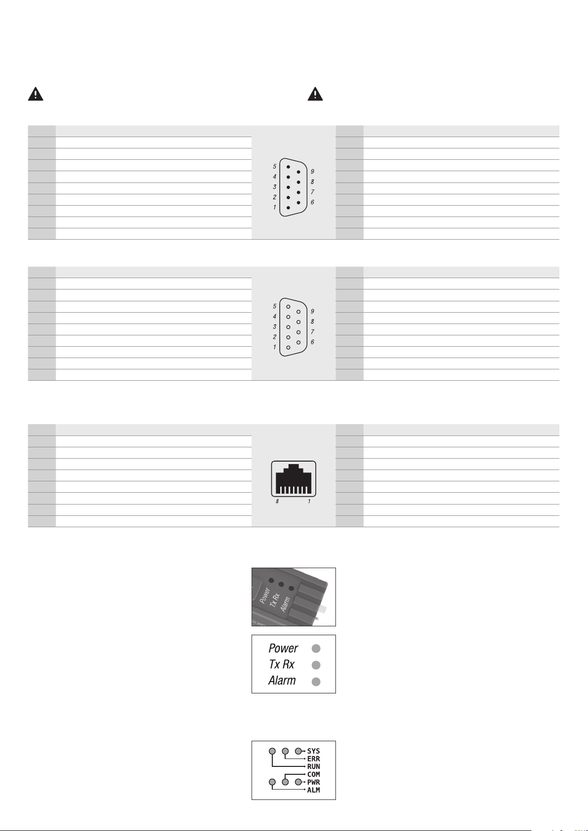
Sub D plug pin assignments Modbu s RTU, power supply & analog signals (male) D-Sub Stecker Pinbelegung Modbus RTU, Stromversorgung & analoge Signale (male)
Pin Assignment Description Pin Belegung Beschreibung
1 Common (-) GND analog signals 1 Common (-) GND Analoge Signale
2 Supply 0 Vdc 0 Vdc supply voltage 2 Supply 0 Vdc 0 Vdc Speisespannung
3 Supply +24 Vdc +24 Vdc supply voltage 3 Supply +24 Vdc +24Vdc Speisespannung
4 Output (+) Analog output, measured value 4 Output (+) Analogausgang, Messwert
5 Setpoint (+) Analog input, setpoint 5 Setpoint (+) Analogeingang, Sollwert
6 Tx+ RS- 485 Out put (Y ) 6 Tx+ RS-485 Ausgang (Y)
7 Tx- RS- 485 Out put (Z) 7 Tx- RS-485 Ausgang (Z)
8 Rx+ RS- 485 Input (B) 8 Rx+ RS-485 Eingang (B)
9 Rx- RS- 485 Inp ut (A) 9 Rx- RS-485 Eingang (A)
Sub D plug pin assignments Profibus (female) D-Sub Stecker Pinbelegung Profibus (female)
Pin Assignment Description Pin Belegung Beschreibung
1 Not connected – 1 Nicht belegt –
2 Not connected – 2 Nicht belegt –
3 RxD/TxD-P Data trans mit / recei ve; data wire B 3 RxD/TxD-P Daten senden / empfangen; Datenader B
4 CNTR-P Repeater control signal (RTS) 4 CNTR-P Repeater Steuersignal (RTS)
5 DGND Ground for data signals and VP 5 DGND Masse für Datensignale und VP
6 VP / +5V Power supply +5V 6 VP / +5V Spannungsversorgung +5V
7 Not connected – 7 Nicht belegt –
8 RxD/TxD-N Data tr ansmit / receive; dat a wire A 8 RxD/TxD-N Daten senden / empfangen; Datenader A
9 Not connected – 9 Nicht belegt gelb/grün
Bei Arbeiten an Steckern immer zuerst die Stromversorgung
trennen!
RJ45 socket pin assignments Profinet / EtherCAT (female) RJ45 Buchse Pinbelegung Profinet / EtherCAT (female)
Pin Assignment Wire color Pin Belegung Drahtfarbe
1 Data ( Tx+) yellow 1 Data ( Tx+) gelb
2 Data (Tx-) orange 2 Data (Tx-) orange
3 Data (Rx+) white 3 Data (Rx+) weiss
4 Not connected – 4 Nicht belegt –
5 Not connected – 5 Nicht belegt –
6 Data (Rx-) blue 6 Data (Rx-) blau
7 Not connected – 7 Nicht belegt –
8 Not connected – 8 Nicht belegt –
LED operating status
Power
The green LED lights up when the unit is supplied with the
correct supply voltage and is ready for operation.
TxR x
The yellow LED flashes when the device is communicating
on the digital Modbus RTU interface.
Alarm
If the red LED flashes, there is a malfunction. If the LED is lit
continuously, there may be a serious problem. Disconnect
the supply voltage and reconnect the device. If the LED is
still lit, the unit must be returned for repair.
LED Betriebszustands-Anzeige
Power
Die grüne LED leuchtet, wenn das Gerät mit der korrekten
Speisespannung versorgt wird und betriebsbereit ist.
TxR x
Die gelbe LED blinkt, wenn das Gerät auf der digitalen
Modbus RTU-Schnittstelle kommuniziert.
Alarm
Blinkt die rote LED, liegt eine nicht schwerwiegende
Betriebs-Störung vor. Leuchtet die LED dauernd, besteht
eventuell ein schwerwiegender Fehler. Unterbrechen Sie
die Speisespannung und stecken Sie das Gerät wieder ein.
Falls danach die Alarm-LED noch immer leuchtet, muss das
Gerät zur Reparatur eingesandt werden.
Note
The EtherCat/Profinet devices have an ex tended LED
operating status. Please refer to the operating instructions.
Hinweis
Die EtherCat/Profinet Geräte verfügen über eine
erweiterte LED Betriebszustands-Anzeige. Bitte
konsultieren sie diesbezüglich die Bedienungsanleitung.
 Loading...