

Vogtlin red-y industrial Series Quick Start Manual
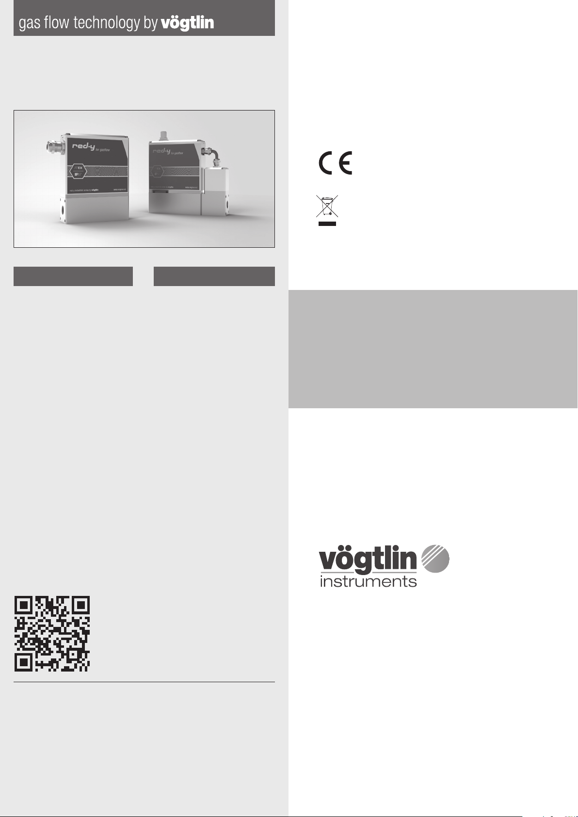
red-y industrial series
Vögtlin Customer Service:
service@voegtlin.com
+41 61 756 63 00
www.voegtlin.com
Quick Start Guide
English Deutsch
Thank you for choosing a Vögtlin
red-y industrial series device
for your application. This Quick
Start Guide will help you to install
and operate the unit. Please
read through these instructions
carefully before you use and install
this flow meter.
Vielen Dank dass Sie sich für ein
Gerät der red-y industrial series
entschieden haben. Dieser Quick
Start Guide wird Ihnen helfen, das
Gerät schnellstmöglich in Betrieb
zu nehmen. Bitte lesen Sie diese
Anleitung aufmerksam durch und
befolgen Sie die darin enthaltenen
Anweisungen.
Please contact our customer ser vice, if you are not able to obtain
the operating manual online.
Sollte es Ihnen nicht möglich sein, die Bedienungsanleitung online
zu beziehen, wenden Sie sich bitte an unseren Customer Service.
Please dispose of the device in an environmentally friendly way
(recycle).
Bitte entsorgen Sie das Gerät fachgerecht (Recycling).
For safe operation, please consider the process and
ambient conditions for which the device is designed and
specified at the time of delivery. This information can be
found on the type plate on the instrument housing and in
the operating manual.
Bitte beachten Sie für eine sichere Inbetriebnahme die
Prozess- und Umgebungsbedingungen, für die das Gerät
zum Zeitpunkt der Lieferung ausgelegt wurde. Diese
Informationen befinden sich auf dem Typenschild auf dem
Gerätegehäuse und in der Bedienungsanleitung.
IMPORTANT: This Quick Start
Guide does not replace the
operating manual!
Please download and read
the operating instructions
carefully before installation and
commissioning.
You can download the complete
red-y industrial manual, the free
configuration software get red-y
and other product information
with the below link:
www.voegtlin.com/go/industrial
This Quick Start Guide is subject
to technical change.
WICHTIG: Dieser Quick Start
Guide ist kein Ersatz für die
Bedienungsanleitung!
Bitte lesen Sie die
Bedienungsanleitung vor dem
Einbau und der Inbetriebnahme
sorgfältig durch.
Sie können die red-y industrial
Bedienungsanleitung, die
kostenlose Konfigurationssoftware get red-y und weitere
Produktinformationen über
folgenden Link beziehen:
Technische Änderungen
vorbehalten.
Vögtlin Instruments GmbH
flow technology
Langenhagstrasse 1
CH- 4147 Aesch BL
Switzerland
Phone +41 61 756 63 00
Fax +41 61 756 63 01
info@voegtlin.com
www.voegtlin.com
© 2019 Vögtlin Instruments GmbH Switzerland
Subject to technical change
811-1220 Industrial Quick Start Guide – V191126

Available Connections
Verfügbare Anschlüsse
1 1 1
Terminal Assignement
Always disconnect the power supply before working on the
terminals and plugs!
Terminal assignment for Modbus RTU, power suppl y & analog signals
1
Terminals Assignment Description
0 Ground Connected to housing
1 Common GND analog signals
2 0 Vdc 0 Vdc supply voltage
3 +24 Vdc +24 Vdc supply voltage
4 Output + Analog output, measured value
Analog SIgnals
Power Sup ply &
5 Setpoint + Analog input, setpoint
6 Tx+ RS- 485 Output (Y )
7 Tx- RS- 485 Output (Z)
8 Rx- RS- 485 Input (B )
Modbus RTU
9 Rx+ RS- 485 Input (A)
10 +5 Vdc Maximum load 100 mA
11 A (-) Profibus- DP Comms (A or - )
12 Ground GND digital signals
Profibus
(optional)
13 B (+) Profibus -DP C omms (B or +)
14 Shield Connection analog ground
15 - (Val ve) Control Valve (for MFC option only)
Valve
16 + (Valve) Control Valve (for MFC option only)
Klemmenbelegung
Bei Arbeiten an Klemmen und Steckern immer zuerst die
Stromversorgung trennen!
Klemmenbelegung für Modbus RTU, Stromversorgung & analoge Signale
1
Terminals Assignment Description
0 Ground An Gehäuse angeschlossen
1 Common Erdung für analoge Signale
2 0 Vdc 0 Vdc Spannungsversorgung
3 +24 Vdc +24 Vdc Spannungsversorgung
4 Output + Analoger Ausgang, Messwert
Analogw SIgnale
5 Setpoint + Analoger Eingang, Sollwert
Stromversorgung &
6 Tx+ RS-485 Ausgang (Y )
7 Tx- RS-485 Ausgang (Z)
8 Rx- RS-485 Eingang (B)
Modbus RTU
9 Rx+ RS-485 Eingang (A)
10 +5 Vdc Max. L ast 10 0 mA
11 A (-) Profibus- DP Comms (A od er -)
12 Ground Erdung für digitale Signale
Profibus
(optional)
13 B (+) Profibus -DP C omms (B oder +)
14 Shield Anschluss analoge Erdung
15 - (Val ve) Regelventilanschluss (nur MFC)
16 + (Valve) Regelventilanschluss (nur MFC)
Ventil
22 23 3 4 4
4
Pin assignment
M12 plug pin assignments Modbus RTU, power supply & analog signals (male)
2
Pin Assignment Wire color Pin Belegung Drahtfarbe
1 RS -485 B (+) (Rx+/Tx+) white 1 RS -485 B (+) (Rx+/Tx+) weiss
2 Output + brown 2 Output + braun
3 Setpoint + green 3 Setpoint + grün
4 0 Vdc yellow 4 0 Vdc gelb
5 Not connected grey 5 Not connected grau
6 RS- 485 A (-) (Rx-/Tx-) pink 6 RS- 485 A (-) (R x-/Tx-) rosa
7 +24 Vdc blue 7 +24 Vd c blau
8 Common red 8 Common rot
M12 plug pin assignments Profibus (female)
3
Pin Assignment Wire color Pin Belegung Drahtfarbe
1 +5 Vdc brown 1 +5 Vdc braun
2 A (-) white 2 A (-) weiss
3 Ground blue 3 Ground blau
4 B (+) black 4 B (+) schwarz
5 Shield yellow/green 5 Shield gelb/grün
M12-D coding plug pin assignment s Profinet / EtherCAT (female)
4
Pin Assignment Wire color Pin Belegung Drahtfarbe
1 D at a ( Tx+) yellow 1 D at a ( Tx+) gelb
2 Data (Rx+) white 2 Data ( Rx+) weiss
3 Da ta (Tx-) orange 3 Da ta (Tx-) orange
4 Data (Rx-) blue 4 Data (Rx-) blau
45°
1
45°
1
45°
1
Steckerbelegung
2
2 3
4
8
5
7
6
3
2
5
3
4
4
2
3
4
M12 Stecker Pinbelegung Modbus RTU, Stromversorgung & analoge Signale (male)
M12 Stecker Pinbelegung Profibus (female)
M12-D coding Stecker Pinbelegun g Profinet / EtherCAT (female)
 Loading...