

Vogtlin Q-Flow 80, V-100 Series, Q-Flow 55, Q-Flow 140, V-100 55 Operating Instructions Manual
...
Vögtlin Instruments AG – flow technology
Langenhagstrasse 1 | 4147 Aesch (Switzerland)
Phone 41 (0)61 756 63 00 | Fax +41 (0)61 756 63 01
www.voegtlin.com | info@voegtlin.com
Handbuch PCU1000
Variable area flowmeters
and high-precision control valves
for gases and liquids
V-Flow Line operating instructions

V-Flow Line
Manual
Version
Page
V-Flow Line
vflow_E4_7
© Vögtlin Instruments AG
02
Operating instructions V-Flow Line
Variable area flowmeters Q-Flow
Variable area flowmeters V-100
High-precision control valves M-Flow
Version: vflow_E4_7
For the latest information on our products, see our website at www.voegtlin.com
© 2010 Vögtlin Instruments AG, Switzerland

V-Flow Line
Manual
Version
Page
V-Flow Line
vflow_E4_7
© Vögtlin Instruments AG
03
Contents
Introduction 5
Service and quality 5
Warranty 5
General instructions 6
Safety information 6
Using the manual 6
General information 7
Operating principle of the variable area flowmeter 7
Variable area flow meter type marking 8
High-precision control valve type marking 8
Technical data 9
Technical data Q-Flow 9
Materials Q-Flow 9
Setups Q-Flow 9
Technical data V-100 10
Materials V-100 10
Setups V-100 10
Technical data M-Flow 11
Materials M-Flow 11
Setups M-Flow 11
M-Flow valve operation options 12
Measuring ranges variable area flowmeters 13
Measuring ranges direct reading scales ln/h (Air) and l/h (Water) 13
Measuring ranges direct reading scales mln/min and ln/min (Air) 14
Measuring ranges mm-scale Q-Flow 14
Measuring ranges mm-scale V-100 14
CV-values high-precision control valves M-Flow 15
Installation and commissioning 16
General instructions 16
Installation instructions 18
Instructions for commissioning 18
Recommended connections 18
Panel mounting Q-Flow 19
Faceplate mounting V-100 20
Limit indicator 21
M-Flow Digiturn installation 24

V-Flow Line
Manual
Version
Page
V-Flow Line
vflow_E4_7
© Vögtlin Instruments AG
04
Disassembly and maintenance 25
Important instructions 25
Disassembly variable area flowmeter Q-Flow 25
Disassembly variable area flowmeter V-100 26
Disassembly Digiturn M-Flow 27
Maintenance 28
Soiling 28
Cleaning 28
Return 28
Appendix 29
Dimensions Q-Flow 29
Dimensions V-100 30
Dimensions M-Flow 31
Type code Q-Flow 33
Type code V-100 34
Type code M-Flow 35
Contamination declaration 37

V-Flow Line
Manual
Version
Page
V-Flow Line
vflow_E4_7
© Vögtlin Instruments AG
05
Introduction
We are glad that you have decided to use our variable area flow meters and high-precision control
valves. Our instruments will provide you with high-quality long-lived products.
This manual contains important information for commissioning and/or designing equipment. Please
contact your distribution partner if anything is not clear.
We are committed to the continual improvement of our products and documentation. Your
experience from everyday use can assist us with this. We welcome your comments and criticisms.
We have taken great care in compiling this manual. However, we cannot accept responsibility for
possible errors.
Service and quality
We are continually improving the quality and provision of our products and services. In the end,
whether the right product was selected only becomes apparent once the product is in use.
Therefore we make every effort not just to preach but also to live by top quality and service.
Warranty
The warranty for the products described in this manual is limited to defects in material and
workmanship. Warranty does in no case exceed product replacement free of charge. All claims are
null and void in the case of improper use:
Use outside the operating limits
Damage due to water hammer
Corrosion damage
Mechanical damage in general
V-Flow Line
Manual
Version
Page
V-Flow Line
vflow_E4_7
© Vögtlin Instruments AG
06
General instructions
Check the package for external damage and contact your distribution partner if the instruments
have visible defects. Check that the delivery is complete and corresponds to the delivery note.
This product is a precision measuring instrument. We would like to point out that you should take
due care when choosing the installation site and following these suggestions and instructions.
Before installing, check that the specification on the type label matches your application.
Please read through these operating instructions carefully before commissioning. Incorrect
operation, errors in comprehension and the consequences of these can lead to breakage of the
instrument or risk of personal injury.
Commissioning and maintenance must be carried out by appropriately qualified personnel. Proper
use of the products is a necessary precondition for their smooth operation.
Safety information
The instruments must not be used outside the specified operating limits
(See also section Technical Data)
Incorrect operation can lead to breakage of the instrument or risk of personal injury.
When using toxic media it is strongly advised not to use glass cylinder measuring instruments:
cylinder breakage and leaks can cause risk of personal injury
Shocks, e.g. caused by magnetic valves, should be avoided.
The measuring instruments must be used solely for the medium specified in the delivery note.
Media which differ from this may lead to impaired durability and therefore cause leakage
Using the manual
This manual contains information on the variable area flowmeters Q-Flow and V-100 and highprecision control valves M-Flow.
Sections and paragraphs which only apply to a particular product group are marked as follows:
Variable area flowmeters Q-Flow
Variable area flowmeters V-100
High-precision control valves M-Flow
V-Flow Line
Manual
Version
Page
V-Flow Line
vflow_E4_7
© Vögtlin Instruments AG
07
General information
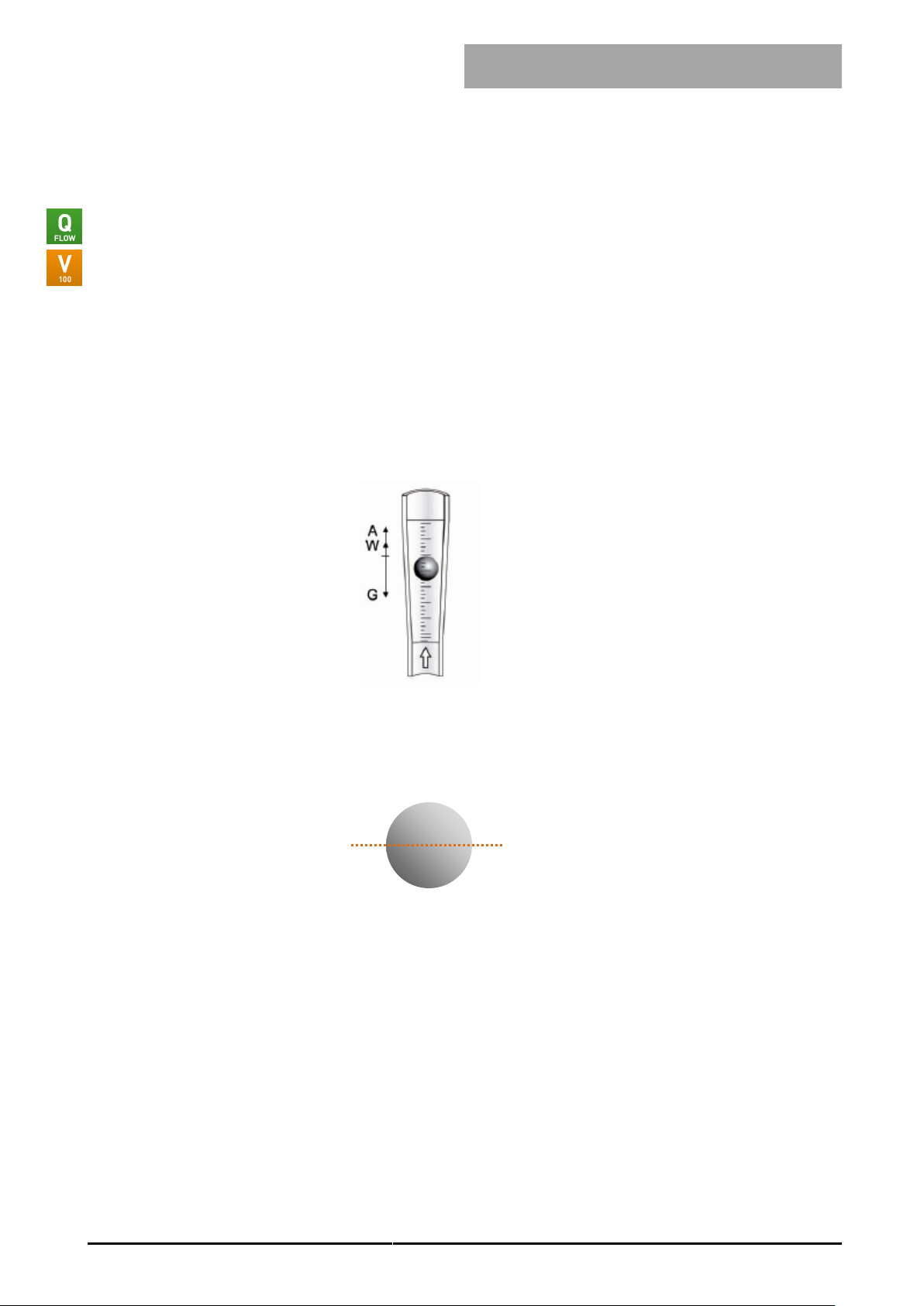
Operating principle of the variable area flowmeter
The measuring instrument works according to the float measuring principle
The measuring unit consists of a tapered graduated precision glass measuring cylinder in which a
ball float can move freely up and down. The medium flows through the vertically-aligned measuring
cylinder from the bottom upwards.
The float positions itself so that the buoyancy force A acting on it, the form resistance W and its
weight G are in balance::
G = A + W
The flow rate can be read as the height of the float on a scale on the tapered measuring cylinder.
The value is read off at the middle of the float (largest diameter).

V-Flow Line
Manual
Version
Page
V-Flow Line
vflow_E4_7
© Vögtlin Instruments AG
08
SN: 483493-1-006 07/08
BE: 133526
Type: FLV-CSSA-SM
Air, 3.6-43 ln/min, 4 bar a, 20°C
mm-Scale
www.voegtlin.com - +41 61 756 63 00
Variable area flow meter type marking
The instrument type label is attached to the inside of the left side panel in the V-100 and on the
back of the mounting plate in the Q-Flow:
Example:
Key:
SN: Serial number – Position – number of instruments per position
BE: Customer order number
07/08: Date of manufacture, month/year
Type: Specification in accordance with type code (standard instruments only) 1
Medium, measuring range, measurement unit, pressure, temperature and additional information.
1
Custom designed instruments are given a seven digit product code instead of a type code
(e.g. 137-1215).
High-precision control valve type marking
For the M-Flow the type label is attached to the valve cartridge housing.
An arrow on the body of the valve indicates the flow direction.
Example:
Key:
NS 2.5: Specification of valve size NS 1.0 to NS 6.5
L: Closing direction for valve (L = left / R = right)
V: Sealing material (V = FKM / E = EPDM / P = FFKM
Custom designed instruments can have additional details such as leakage rate.
V-Flow Line
Manual
Version
Page
V-Flow Line
vflow_E4_7
© Vögtlin Instruments AG
09
Type
Q-Flow 55
Q-Flow 80
Q-Flow 140
Turndown ratio
10:1
10:1
10:1
Accuracy in % of full scale
± 5 %
± 4 %
± 2 %
Measuring tube length
55 mm
80 mm
140 mm
Scale length
40 mm
65 mm
120 mm
Float
spherical
spherical
spherical
Max. pressure
20 bar
20 bar
16 bar
Max. pressure drop
100°C
100°C
100°C
Component
Aluminium
Stainless steel
Top and base sections*
Anodized aluminum
Stainless steel 1.4305
Mounting plate
Anodized aluminum
Anodized aluminum
Measuring cylinder*
Borosilicate glass
Borosilicate glass
Connections*
Nickel-plated brass
Stainless steel 1.4305
Float*
SS 316 L / Glass / Ceramic
SS 316 L / Glass / Ceramic
Valve*
Nickel-plated brass
Stainless steel 1.4305
Seals*
FKM
FKM/EPDM
Front cover
Makrolon (Polycarbonate)
Makrolon (Polycarbonate)
Shock absorbing limit stop*
Stainless steel 1.4305 / PTFE
Stainless steel 1.4305 / PTFE
*Wetted parts
Technical data
Technical data Q-Flow
Materials Q-Flow
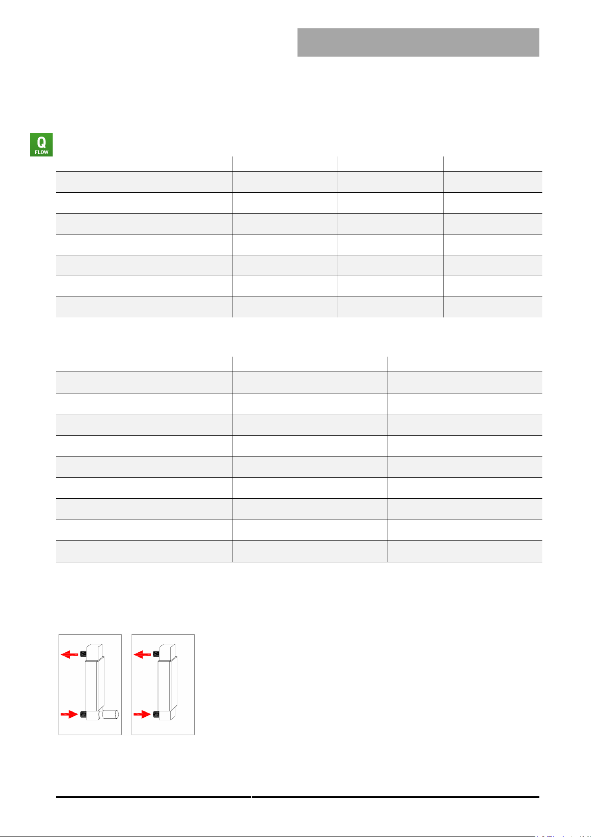
Setups Q-Flow
Standard (process connection on the back)
With valve Without valve
V-Flow Line
Manual
Version
Page
V-Flow Line
vflow_E4_7
© Vögtlin Instruments AG
10
Type
V-100 55
V-100 80
V-100 140
Turndown ratio
10:1
10:1
10:1
Accuracy in % of full scale
± 5 %
± 4 %
± 2 %
Measuring tube length
55 mm
80 mm
140 mm
Scale length
40 mm
65 mm
120 mm
Float
spherical
spherical
spherical
Max. pressure
20 bar
20 bar
16 bar
Max. pressure drop
100°C
100°C
100°C
Component
Aluminium
Stainless steel
Top and base sections*
Anodized aluminum
Stainless steel 1.4305
Mounting plate
Anodized aluminum
Anodized aluminum
Measuring cylinder*
Borosilicate glass
Borosilicate glass
Connections*
Nickel-plated brass
Stainless steel 1.4305
Float*
SS 316 L / Glass / Ceramic
SS 316 L / Glass / Ceramic
Valve*
Nickel-plated brass
Stainless steel 1.4305
Seals*
FKM
FKM/EPDM
Front cover
Makrolon (Polycarbonate)
Makrolon (Polycarbonate)
Shock absorbing limit stop*
Stainless steel 1.4305 / PTFE
Stainless steel 1.4305 / PTFE
*Wetted parts
Technical data V-100
Materials V-100
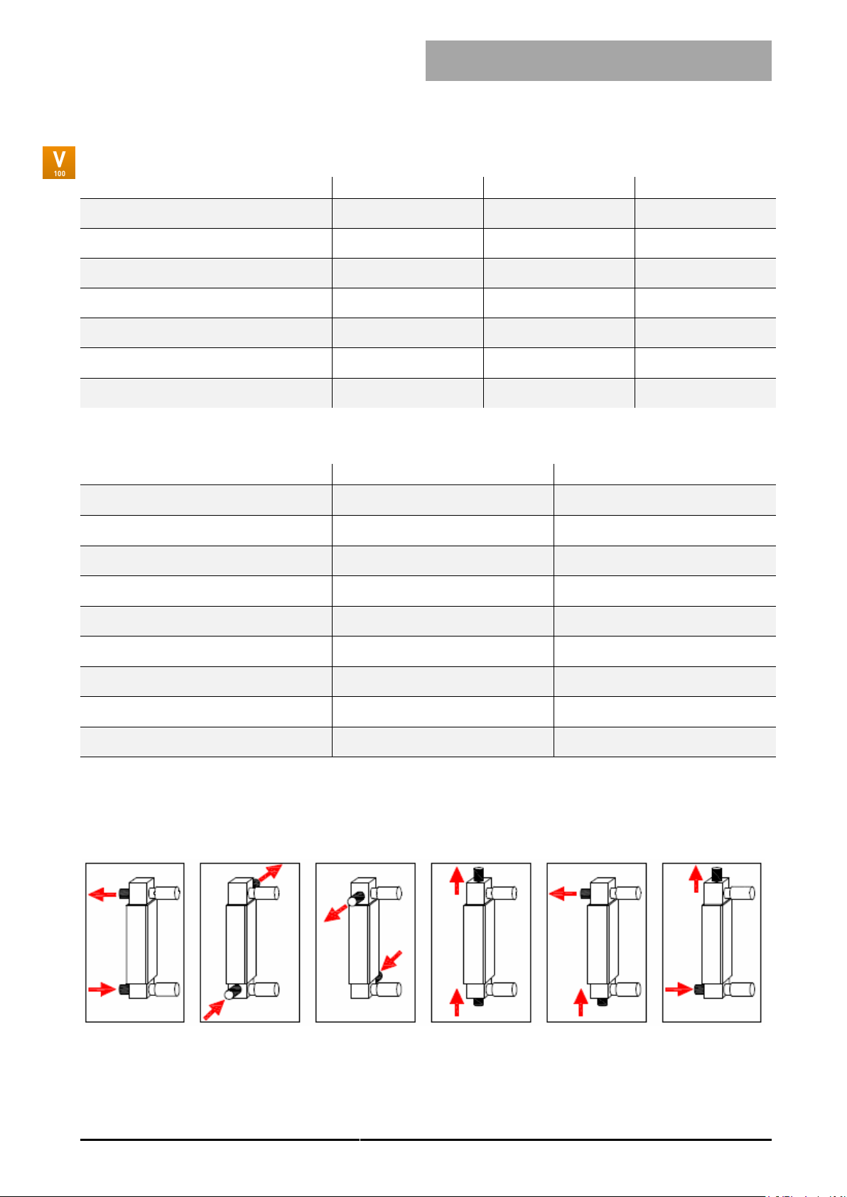
Setups V-100 (position of the process connection)
Standard Setup L Setup R Setup A* Setup T* Setup O*
*A, T and O-Type in stainless steel only
V-Flow Line
Manual
Version
Page
V-Flow Line
vflow_E4_7
© Vögtlin Instruments AG
11
Type
M-Flow 25
M-Flow 35
M-Flow V-Stack
Straight valve
Corner valve
Valve insert/cartridge
Gas distribution system
Ccw-closed
Valve turns
15
15
15
Valve size
NS 1.0 bis 3.0
NS 4 und 6.5
NS 4 und 6.5
Leak rate
<1x10⁻⁵ mbar l/s He
<1x10⁻⁵ mbar l/s He
<1x10⁻⁵ mbar l/s He
Max. pressure
20 bar
20 bar
20 bar
Min. temperature
-40°C
-40°C
-40°C
Max. temperature
150°C
150°C
150°C
Component
Aluminium
Edelstahl
Valve*
Anodized aluminum
Stainless steel 1.4305
Valve insert/cartdrige *
Nickel-plated brass
Stainless steel 1.4305
Connections*
Nickel-plated brass
Stainless steel 1.4305
Seals*
FKM
FKM/EPDM/FFKM
* Wetted parts
Technical data M-Flow
Materials M-Flow
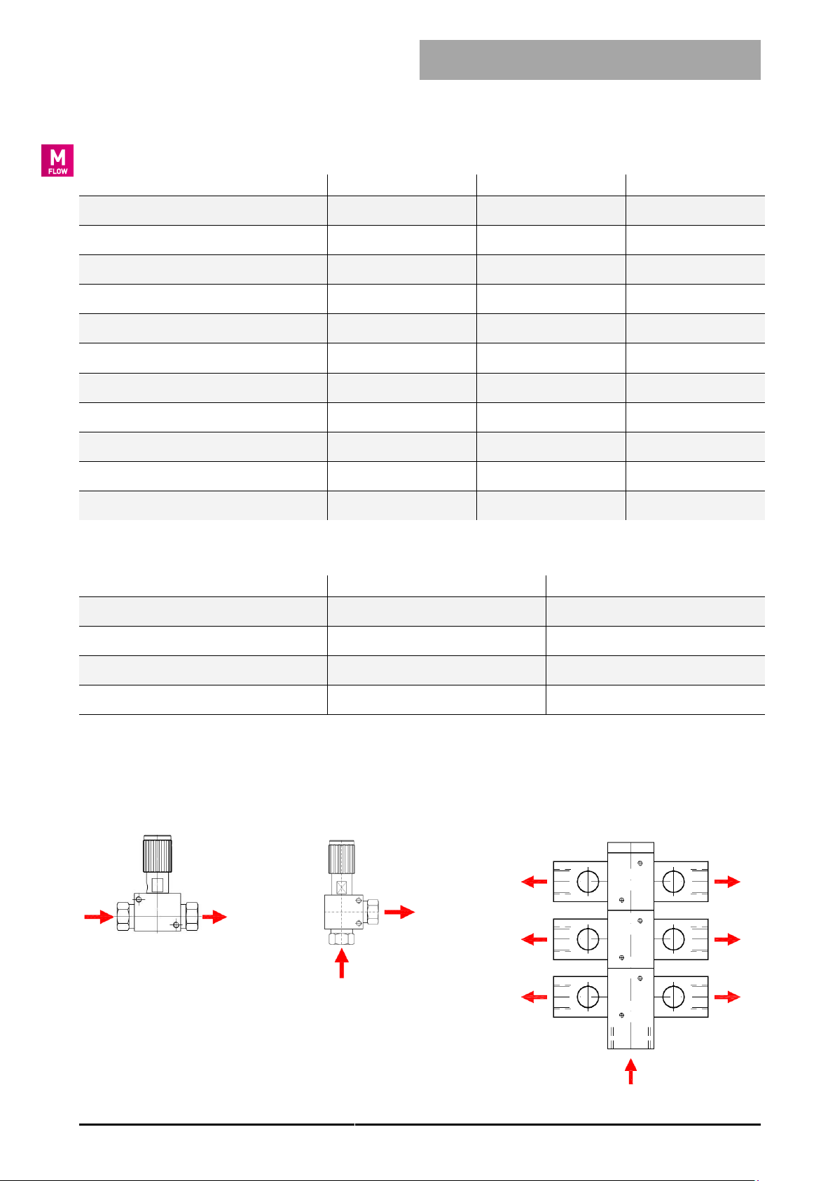
Setups M-Flow
Straight valve Corner valve Distribution system V-Stack

V-Flow Line
Manual
Version
Page
V-Flow Line
vflow_E4_7
© Vögtlin Instruments AG
12
Standard-knob
Standard-knob with locking ring
Hex socket and locking nut (instead of standard-knob)
Digiturn with indication
(100 divisions, cw-closed valve only)
Digi-knob
(100 divisons, ccw-closed valve only)
basic valve right- or left-handed
thread made from brass or
stainless steel
stop ring 518-1552
manual knob
manual knob
headless screw M3x6 512-8204
headless screw M5x5
disc Ø10x6.4/0.5 518-1550
locking nut 518-1554
2 x headless screw M3x3 512-8201
2 x headless screw M3x4 512-8202
2 x headless screw M3x3 512-8201
2 x headless screw M4x10 512-8217
headless screw M3x6 512-8204
digiturn knob 633-1102
reducing bush 518-1575
collar ring 518-1563
cover ring 633-1104
stargrip to digiturn knob 633-1103
digivö knob 633-1101
digibase 518-1553
M-Flow valve operation options
The following valve operation options are available (see also the type code of each instrument):
 Loading...