

Vogelzang International VG900 Owner's Manual

OWNERS MANUAL
Model VG900
THERMOSTAT CONTROLLED DUAL FUEL CIRCULATOR SERIES
SAFETY NOTICE:
If this heater is not properly installed, a house re may result.
To reduce the risk of re, follow the installation instructions.
Contact local building or re ofcials about permits, restrictions
and inspection requirements in your area.
• ASSEMBLY
• INSTALLATION
• OPERATION
• REPAIR PARTS
Conforms To:
UL STD 1482;
ULC STD S627
852083
United States Stove Company
227 Industrial Park Rd.
P.O. Box 151 South Pittsburg, TN 37380
(800) 750-2723
www.vogelzang.com
Hearth Deluxe
CAUTION:
Please read this entire manual before you install and use your
new room heater. Failure to follow instructions may result in prop-
erty damage, bodily injury, or even death.
DO NOT USE THIS HEATER IN A MOBILE HOME OR TRAILER
Ê É
Fold Here Fold Here
PLACE
STAMP
HERE
United States Stove Company
P.O. Box 151
South Pittsburg, TN 37380
" CUT HERE " CUT HERE
TOOLS AND MATERIALS NEEDED
TOOLS
• Pencil
• Measuring Tape or 6 foot rule
• Tin Snips
• Drill and 1/8” dia. bit
• Gloves
• Screwdriver (Blade type)
• 5/16” Nut Driver or
5/16” Socket w/Ratchet
MATERIALS
• Chimney Connection- 6” Diameter Black Steel
pipe (24 gauge minimum) and elbow(s) either
adjustable1 or corrugated as necessary
• 1/2” Sheet Metal Screws
• 6” Inside Diameter Underwriters Laboratories
(UL) listed Residential Type and Building Heating
Appliance Chimney, Type “HT”, or 6” existing
Masonry Chimney with ue liner.
• Floor Protector Material: 3’ x 4’-6” (as specied
on page 4.)
• Furnace Cement (Manufacturer recommends:
Rutland Code 78 or Equivalent)
1
Avoid adjustable elbows, they leak!
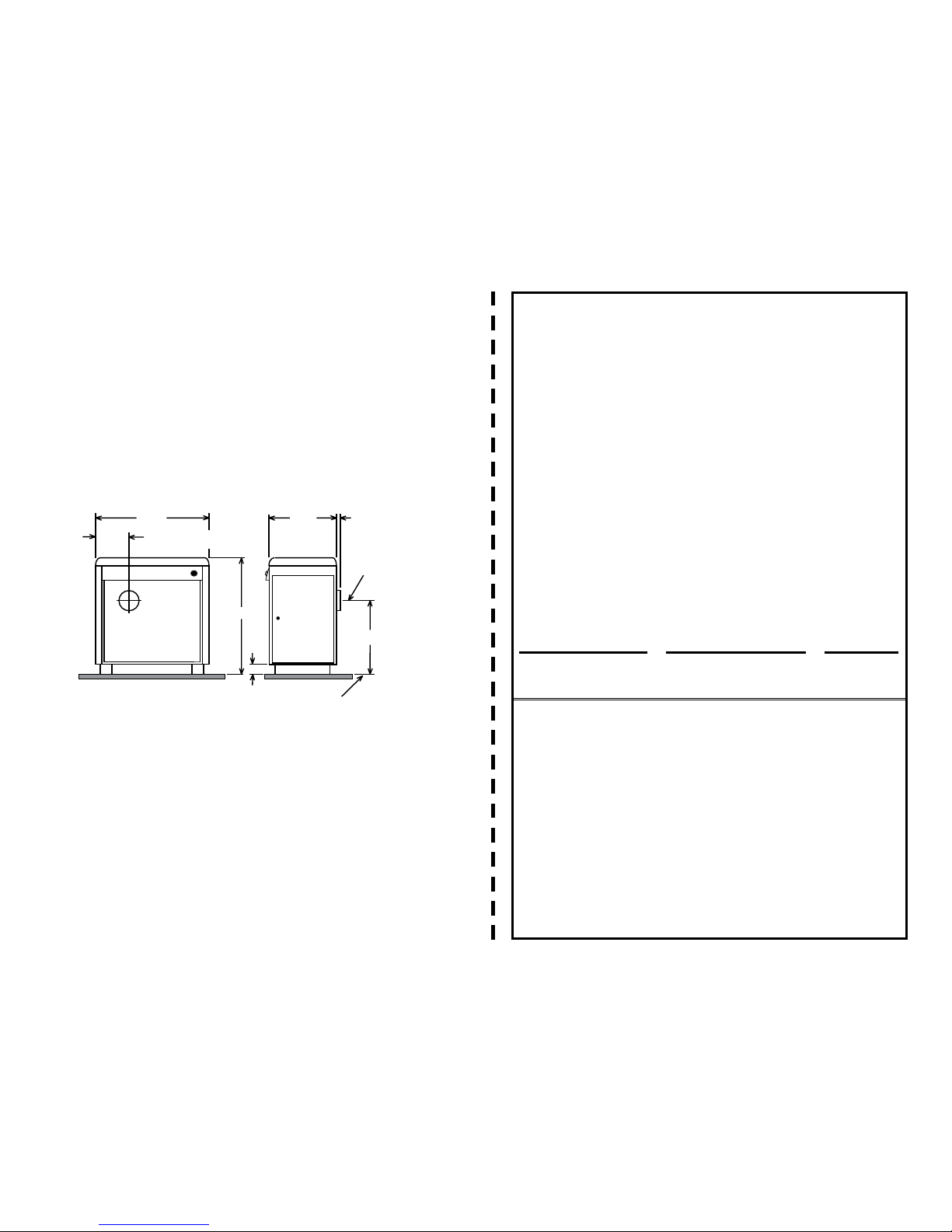
32 1/4
12 1/2
33 1/2
4 1/8
4 1/4
19 1/4
CENTER LINE OF 6"
CHIMNEY CONNECTOR
24
CENTER LINE
OF 6"
CHIMNEY
CONNECTOR
CIRCULATOR DIMENSIONS
RULES FOR SAFE INSTALLATION AND OPERATION
Save These Instructions! Read these rules and the instructions carefully.
1.
Check local codes. The installation must
comply with their rulings. Do not install this
heater in a mobile home or trailer.
2. Always connect this heater to a chimney or
vent to the outside. Never vent to another
room or inside a building.
3. Do not connect this heater to an aluminum
Type B gas vent. This is not
safe and is prohibited by all codes. This heater requires
connection to approved
chimneys: Either a
chimney complying with the requirements
for Type HT chimneys in the Standard for
Chimneys. Factory Built, Residential Type
and Building Heating Appliance, UL 103, or
a code approved masonry chimney with a
ue liner
, preferably round. A larger
masonry
ue may be used, so long as the ue-section
diameter is not greater than 50 sq. in.
4. The chimney portion (whether factor-built
or masonry) must be tall enough to provide
sufcient draft and safe exit of smoke and
combustion products.
5. Be sure that your Chimney is safely constructed and in good repair. Have the
chimney inspected by the Fire Department
or a qualied inspector (such as a Chimney
sweep). Your insurance company may be
able to recommend a qualied inspector.
6. Inspect chimney connector and chimney
twice monthly during the heating season for
any deposit of creosote or soot which must
be removed.
7. Provide air for combustion from outside the
house into the room where the heater is located. If the intake is not in the same room,
air must have free access to the room.
WARRANTY INFORMATION CARD
Name___________________________________________________ Telephone #: (_____) ___________
City ________________________________________________State__________Zip ___________________
Email Address ___________________________________________________________________________
Model # of Unit ________________________________ Serial # __________________________________
Fuel Type: qWood qCoal
Place of Purchase (Retailer) ______________________________________________________________
City ________________________________________________State__________Zip ___________________
If internet purchase, please list website address ___________________________________________
Date of Purchase ________________________________________________________________________
I have read the owner’s manual that accompanies this unit and fully understand the:
Installation
q
Operation
q
and Maintenance
q
of my new appliance.
Print Name Signature Date
Please attach a copy of your purchase receipt.
Warranty not valid without a Proof of Purchase.
Warranty information must be received within 30 days of original purchase.
Detach this page from this manual, fold in half with this page to the inside and tape together.
Apply a stamp and mail to the address provided. You may use an envelope if you choose.
You may register online by going to www.usstove.com
All information submitted will be kept strictly condential. Information provided will not be sold for advertising
purposes. Contact information will be used solely for the purpose of product notications.
" CUT HERE " CUT HERE
2
8. CAST IRON PARTS MUST BE “SEASONED” TO
AVOID CRACKING. BUILD ONLY SMALL FIRES
ON FIRST USE.
9. To prevent injury, do not allow anyone to use
this heater who is unfamiliar with the correct
operation of the heater. Do not allow children
to use or in any way operate this heater.
CAUTION: DO NOT TOUCH THE HEATER UNTIL IT
HAS COOLED. ALWAYS WEAR GLOVES WHEN
REFUELING THIS UNIT OR WORKING WITH METAL
CABINET PARTS.
10. K
eep the ash pit section free of excess
ashes.
Do not allow ashes to stack higher than the
sides of the ash pan. Never allow the ashes
to contact the grate.
11. CAUTION: The special paints used on your
heater may give off some smoke while they
are curing during rst few res. Build small res
at rst. The metal used in construction of the
heater has a light coating of oil. This could
give off smoke and/or odors when heater is
used for the rst couple of times. This should
disappear after a short period. Once this
burn-off has occurred, it should not reoccur.
12. CARING FOR PAINTED PARTS- This heater has
a painted outside jacket, which is durable
but will not stand rough handling or abuse.
When installing your heater, use care in
handling. Clean with soap and warm water
when heater is not hot. DO NOT use any harsh
chemicals (acids or caustics) or scouring
powder, as these wear and dull the nish.
13. KEEP THE FEED DOOR, ASH DOOR AND CABINET
DOOR CLOSED AT ALL TIMES EXCEPT WHILE
TENDING THE HEATER. KEEP SEALS IN GOOD
CONDITION. DO NOT OVERFIRE THE HEATER.
THIS WILL HAPPEN IF THE FEED DOOR, OR
PARTICULARLY THE ASH DOOR, IS LEFT OPEN
DURING OPERATION. UNDER EXTREME CONDITIONS THIS CAN PRODUCE DANGEROUS
RESULTS. AT A MINIMUM, IT WILL ALLOW THE
PAINT TO DISCOLOR.
14. DO NOT USE the coal bricks that are manufac-
tured from coal dust and a wax-type binder.
15. Use smoke detectors in the room where your
heater is installed. We recommend installing
smoke detectors in your home if not already
installed.
16. DO NOT connect this heater to any air distribution duct or system.
17. Never use make-shift compromises during
the installation.
18. For further information on using your heater
safely, obtain a copy of the National Fire
Protection Association (NFPA) publication
“Using Coal and Wood Stoves Safely” NFPA
No. HS-10-1978. The address of the NFPA is
Battery March Park, Quincy, MA. 02269.
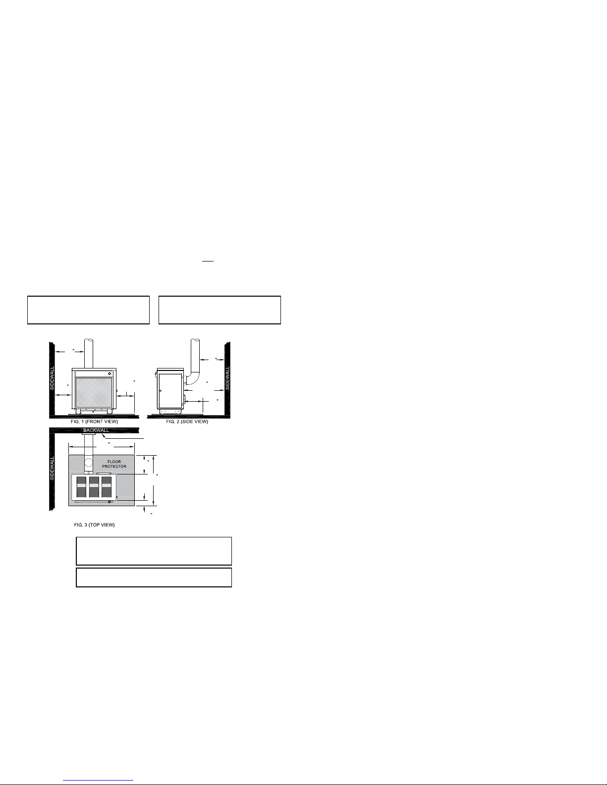
MINIMUM CLEARANCES TO COMBUSTIBLE WALLS AND CEIL
INGS
Minimum clearances to unprotected combustible walls and ceilings as noted by gures 2
through 4 must be maintained. Drapes, curtains,
furniture and other combustible materials should
be kept much further away from the heater
to avoid re. If you choose to, you may install
the heater and chimney connector closer to
combustible surfaces than indicated by Figures
2 through 4 IF a clearance reduction system is
also installed to protect combustible ceilings and
walls near the heater and chimney connector.
However, there are limits to how close the heater
and chimney connector can be installed to
combustible surfaces protected by a clearance
reduction system.
A correctly installed clearance reduction system
protects the combustible surfaces well beyond
the sides and above the top of the heater and
beyond the sides and top of the chimney connector pipe.
Two common types of clearance reduction
systems use sheet metal with a minimum thickness of 28 gauge (galvanized steel, aluminum,
copper) or a 3-1/2 inch (4 inch nominal) thick
masonry wall. Either of these materials must be
spaced out 1 inch from the combustible surfaces.
With sheet metal, non-combustible spacers are
used to maintain the 1 inch air space. With a
masonry wall, metal wall ties and furring strips, if
needed are used to anchor the brick to the wall.
To avoid excessive heat transmission, the spacers
or wall ties should not be placed directly behind
the heater or chimney connector. The 1 inch air
space provides free air circulation. It is essential
that there be openings at the top and bottom of
these clearance reducers so cool air can enter
at the bottom and hot air exit at the top. It is
the “chimney effect” whereby when the air in
the space is heated, it rises exiting from the top
and being replaced by cooler air at the bottom,
that makes these shields effective.
Masonry, or other non-combustible products, attached directly to a combustible surface without
an air space offer very little protection and can-
not be considered a clearance reducer unless
specied materials have been tested and listed
for direct attachment to a combustible surface.
The same applies to thin veneer brick and stone
coverings. These materials provide adequate
protection only when mounted on sheet metal
with a 1 inch spacing to the wall.
A variety or prefabricated clearance reduction
systems which have been tested and listed are
available through heater dealers. Always look
for a safety listing label on the product when selecting a clearance reduction system and make
sure it is designed for solid fuel appliances. The
manufactures of these systems provide specic
installation instructions that must be followed
exactly for a safe installation.
HOW TO ORDER REPAIR PARTS
This manual will help you to obtain efcient, dependable service from
the heater, and enable you to order repair parts correctly.
Keep this manual in a safe place for future reference.
When writing, always give the full model number which is on the
nameplate attached to the inside of the cabinet door of the heater.
When ordering repair parts or options, always give the fol-
lowing information as shown in this list:
1. The PART NUMBER
2. The PART DESCRIPTION
3. The MODEL NUMBER:________________
4. The SERIAL NUMBER:________________
Before installing your heater, ll in the serial number of your heater in
the space provided above.
United States Stove Company
227 Industrial Park Rd.
P.O. Box 151 South Pittsburg, TN 37380
(800) 750-2723
www.vogelzang.com
CC
SS
SS
UU
C
O
M
P
A
N
Y
U
N
I
T
E
D
S
T
A
T
E
S
S
T
O
V
E
3
LOCATING THE HEATER
AS A LOCATION IS SELECTED, KEEP THE FOLLOWING MIND:
1. The chimney connection should be as airtight
as possible. The heater must have its own
chimney ue. Do not connect this unit to a
chimney ue serving another appliance. If
there is no chimney near where you wish to
place the heater, you can use a UL 103HT
Residential Type and Building Heating Appliance Chimney.
2. Place the heater on solid masonry or solid
concrete. When the heater is used on a
combustible oor, use a non-combustible
oor protector of one layer of 3/8" millboard
having a thermal conductivity of K=0.84 BTU
in./ft. 2 hr. Deg. F with 28-gauge sheet metal
or a UL 1618 Listed oor protector with 0.45
R-Value. Have the oor protector extend 16"
beyond the door side of the heater and under
the connector pipe in the back.
3. Check Figures 2, 3, and 4. Be sure you have
the clearances shown from the heater and
the connector pipe to combustible surfaces.
If you have a solid brick or stone wall behind
your heater, you can place the heater as
close as you wish to the wall. If the wall is
only faced with brick or stone, treat it as a
combustible wall.
4 3/4
(121mm)
54
(1.37M)
*16
(406mm)
25
(635mm)
35
(989mm)
12
(305mm)
25
(635mm)
*17
(432mm)
12
(305mm)
36
(914mm)
INCHES (METRIC)
NOTE: DASHED LINES SHOW
STRAIGHTUP AND DOWN THROUGH
THE WALL INSTALLATION.
*CANADIAN INSTALLATIONS REQUIRE
A MINIMUM OF 18” (450mm) ON THE
FUEL LOADING SIDE AND 8”(203mm)
ON ALL OTHER SIDES.
NON-COMBUSTIBLE CONSTRUCTION
IN ACCORDANCE WITH NFPA 211
AND CAN/CSA-B365-M91
NOTE: BEFORE FIRING HEATER
Slide rebricks toward the rear so no
gaps remain between them.
CAUTION:
Keep furnishings and other combus-
tible materials away from the heater.
NOTES
4 21
NOTICE:
Clearances stated above may ONLY be reduced
by means approved by the regulatory authority.
DO NOT CONNECT TO OR USE IN CONjUNCTION WITH
ANY AIR DISTRIBUTION DUCT OR SYSTEM.
 Loading...