

Vogelzang International VG5790 Owner's Manual
MODEL: VG5790
Certifi ed for installations in the USA and Canada.
Approved for installation in mobile homes
French version is available for download from the Vogelzang website: http://www.Vogelzang.com/
PLEASE READ THIS ENTIRE MANUAL BEFORE INSTALLATION AND USE OF THIS APPLIANCE.
FAILURE TO FOLLOW THESE INSTRUCTIONS COULD RESULT IN PROPERTY DAMAGE, BODILY
INJURY, OR EVEN DEATH.
CONTACT YOUR LOCAL BUILDING OR FIRE OFFICIALS ABOUT OBTAINING PERMITS, RE-
STRICTIONS, AND INSTALLATION INSPECTION REQUIREMENTS IN YOUR AREA.
SAVE THESE INSTRUCTIONS.
This unit is not intended to be used as a primary source of heat.
227 Industrial Park Road, South Pittsburg, TN 37380
FOR TECHNICAL ASSISTANCE: Phone 1-800-222-6950 www.Vogelzang.com
OWNER’S MANUAL
U.S. Stove Company
Part No.: 852069 Rev C

Safety Precautions
IMPORTANT: Read this entire manual before install-
ing and operating this product. Failure to do so may
result in property damage, bodily injury, or even death.
Proper installation of this stove is crucial for safe and
efficient operation.
Install vent at clearances specified by the vent manu-
facturer.
Do not connect the pellet vent to a vent serving any
other appliance or stove.
Do not install a flue damper in the exhaust venting
system of this unit.
Use of outside air is not required for this unit, unless
installed in an area with tight construction, or a mobile
home.
Contact your local building officials to obtain a permit
and information on any additional installation restrictions
or inspection requirements in your area.
Do not throw this manual away. This manual has im-
portant operating and maintenance instructions that you
will need at a later time. Always follow the instructions
in this manual.
This appliance is designed for the use of pelletized fuel
that meet or exceed the standard set by the Pellet Fuel
Institute(PFI). The use of other fuels will void warranty.
Never use gasoline, gasoline-type lantern fuel, kero-
sene, charcoal lighter fluid, or similar liquids to start or
‘freshen up’ a fire in this stove. Keep all such liquids
well away from the stove while it is in use.
A working smoke detector must be installed in the same
room as this product.
Install a smoke detector on each floor of your home;
incase of accidental fire from any cause it can provide
time for escape.
The smoke detector must be installed at least 15 feet
(4,57 M) from the appliance in order to prevent unnecessary triggering of the detector when reloading.
Do not unplug the stove if you suspect a malfunction.
Turn the ON/OFF SWITCH to “OFF” and contact your
dealer.
Your stove requires periodic maintenance and cleaning
(see “MAINTENANCE ”). Failure to maintain your stove
may lead to improper and/or unsafe operation.
Disconnect the power cord before performing any
maintenance! NOTE: Turning the ON/OFF Switch to
“OFF” does not disconnect all power to the electrical
components of the stove.
Never try to repair or replace any part of the stove un-
less instructions for doing so are given in this manual.
All other work should be done by a trained technician.
Do not operate your stove with the viewing door open.
The auger will not feed pellets under these circumstances
and a safety concern may arise from sparks or fumes
entering the room.
Allow the stove to cool before performing any mainte-
nance or cleaning. Ashes must be disposed in a metal
container with a tight fitting lid. The closed container of
ashes should be placed on a non-combustible surface or
on the ground, well away from all combustible materials,
pending final disposal.
The exhaust system should be checked monthly during
the burning season for any build-up of soot or creosote.
Do not touch the hot surfaces of the stove. Educate all
children on the dangers of a high-temperature stove.
Young children should be supervised when they are in
the same room as the stove.
The hopper and stove top will be hot during operation;
therefore, you should always use some type of hand
protection when refueling your stove.
A power surge protector is required. This unit must be
plugged into a 110 - 120V, 60 Hz grounded electrical outlet.
Do not use an adapter plug or sever the grounding plug.
Do not route the electrical cord underneath, in front of, or
over the heater. Do not route the cord in foot traffic areas
or pinch the cord under furniture.
The heater will not operate during a power outage. If a
power outage does occur, check the heater for smoke spillage and open a window if any smoke spills into the room.
The feed door must be closed and sealed during operation.
Never block free airflow through the open vents of the unit.
Keep foreign objects out of the hopper.
The moving parts of this stove are propelled by high torque
electric motors. Keep all body parts away from the auger
while the stove is plugged into an electrical outlet. These
moving parts may begin to move at any time while the
stove is plugged in.
Do not place clothing or other flammable items on or near
this stove.
When installed in a mobile home, the stove must be
grounded directly to the steel chassis and bolted to
the floor. WARNING—THIS UNIT MUST NOT BE INSTALLED IN THE BEDROOM (per HUD requirements).
CAUTION—THE STRUCTURAL INTEGRITY OF THE
MOBILE HOME FLOOR, WALL, AND CEILING/ROOF
MUST BE MAINTAINED.
This appliance is not intended for commercial use.
CAUTION: Burning fuel creates carbon monoxide and can
be hazardous to your health if not properly vented.
This appliance should not be a primary source of heat as it
is possible to be down for maintenance and repairs.
* This appliance is a freestanding heater. It is not intended to be attached to any type of ducting. It is not a furnace.
2
SPECIFICATIONS
HEATING SPECIFICATIONS
Fuel Burn Rate* (lowest setting) 1.5 lbs./hr. (0.5 kg/hr)
Burn Time (lowest setting) 80 hrs. (approximate)
Hopper Capacity 120 lbs. (55kg)
* Pellet size may effect the actual rate of fuel feed and burn times. Fuel feed rates may vary by as much as 20%. Use PFI listed fuel for best results.
DIMENSIONS
Height 37.5in. (878mm)
Width 27 in. (686mm)
Depth 27.8 in. (707mm)
Weight 245 lbs. (111.1kg)
ELECTRICAL SPECIFICATIONS
Electrical Rating 110-120 volts, 60 HZ, 3.0 Amps
Watts (operational) 180
Watts (igniter running) 346
FUEL CONSIDERATIONS
Your pellet stove is designed to burn premium hardwood pellets that comply with Association of Pellet Fuel Industries
standards. (Minimum of 40 lbs density per cubic ft, 1/4” to 5/16” diameter, length no greater than 1.5”, not less than
8,200 BTU/lb, moisture under 8% by weight, ash under 1% by weight, and salt under 300 parts per million). Pellets that
are soft, contain excessive amounts of loose sawdust, have been, or are wet will result in reduced performance.
Store your pellets in a dry place. DO NOT store the fuel within the installation clearances of the unit or within the space
required for refueling and ash removal. Doing so could result in a house fi re.
Do not overfi re or use volatile fuels or combustibles, Doing so may cause personal and property damage hazards.
SAFETY AND EPA COMPLIANCE
Your pellet stove has been approved for installation in the USA and Canada. It may also be installed in a
manufactured or mobile home. Your stove conforms to ASTM E 1509, 2004, and Certifi ed to ULC S627, 2000,
and(UM) 84-HUD by INTERTEK Testing Services in Fairview, Oregon USA.
3
INSTALLATION
INSTALLATION OPTIONS
Read this entire manual before you install and use your pellet stove. Failure to follow instructions may result
in property damage, bodily injury, or even death!
(See specifi c installation details for clearances and other installation requirements)
A Freestanding Unit—supported by pedestal/legs and placed on a non-combustible fl oor surface in compliance with
clearance requirements for a freestanding stove installation.
An Alcove Unit—supported by pedestal/legs and placed on a non-combustible fl oor surface in compliance with clearance
requirements for an alcove installation.
Your pellet stove may be installed to code in either a conventional or mobile home (see SPECIAL MOBILE HOME REQUIREMENTS). The installation must comply with the Manufactured Home and Safety Standard (HUD), CFR3280, Part
24.
It is recommended that only a authorized technician install your pellet stove, preferably an NFI certifi ed specialist.
DO NOT CONNECT THIS UNIT TO ANY AIR DISTRIBUTION DUCT OR SYSTEM.
The use of other components other than stated herein could cause bodily harm, heater damage, and void your warranty.
IMPROPER INSTALLATION: The manufacturer will not be held responsible for damage caused by the malfunction of a stove due to improper venting or installation. Call (800) 750-2723 and/or consult a professional installer
if you have any questions.
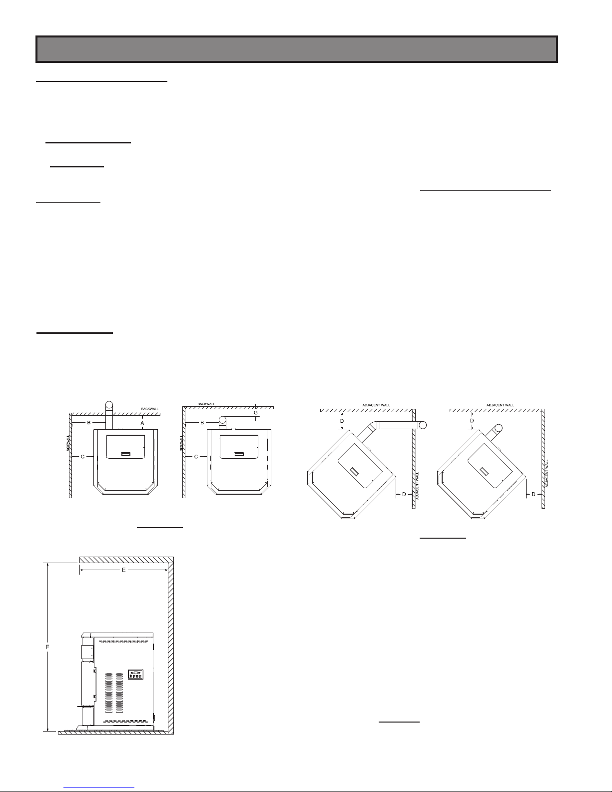
CLEARANCES
Your pellet stove has been tested and listed for installation in residential, mobile home, and alcove applications in
accordance with the clearances given in FIGURES 3-6 and TABLE 1. For safety reasons, please adhere to the installation
clearances and restrictions. Any reduction in clearance to combustibles may only be done by means approved by a
regulatory authority.
FIGURE 3
SIDEWALL CLEARANCES
PARALLEL INSTALLATION
4
FIGURE 4
SIDEWALL CLEARANCES
CORNER INSTALLATION
PARALLEL A - Backwall to unit 8.00 / 203mm
B - Sidewall to fl ue 12.50 / 317mm
C - Sidewall to top edge of unit 8.00 / 203mm
CORNER D - Adjacent wall to unit 3.00 / 76mm
ALCOVE E - Alcove depth 36.00 / 914mm
F - Alcove height 60.00 / 1524mm
G - Backwall to Flue 2.00 / 50mm
TABLE 1
CLEARANCES
Installation
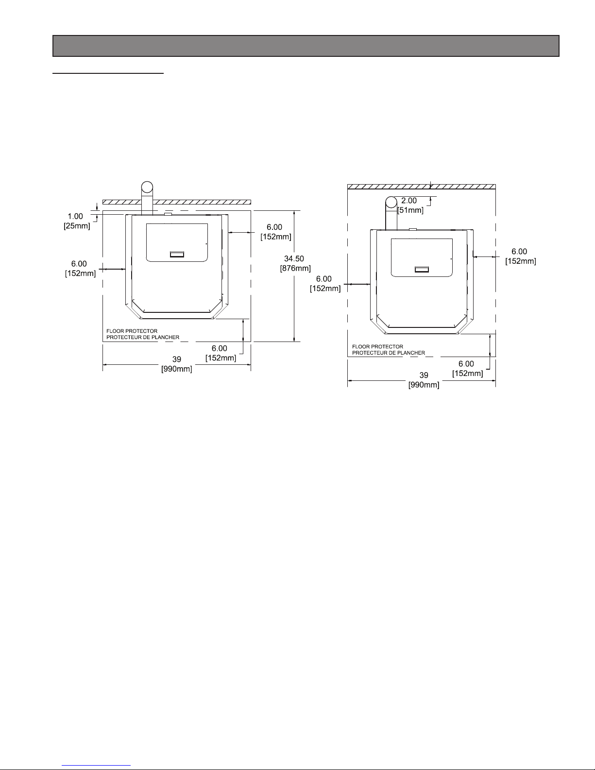
FLOOR PROTECTION
This heater must have a non-combustible fl oor protector (ember protection) installed beneath it if the fl oor is of com-
bustible material. If a fl oor pad is used, it should be UL listed or equal. The fl oor pad or non-combustible surface
should be large enough to cover at least the area under the product and 6 in. (152 mm) beyond the front and beyond
each side of the fuel loading and ash removal openings. Floor protection must extend under and 2 in. (50.8mm) to
each side of the chimney tee for an interior vertical installation (see FIGURE 2).
Canadian Installations require a minimum of 450 mm [17.7”] beyond the front of the unit and 200mm [7.8”] beyond
each side of the unit. A Floor Protector of ¼ inch thick is recommended for this installation.
FIGURE 1
Through the wall installation
FIGURE 2
Interior vertical installation
5
Installation
VENTING REQUIREMENTS
Install vent at clearances specifi ed by the vent manufacturer.
Do not connect the pellet vent to a vent serving any other appliance or stove.
Do not install a fl ue damper in the exhaust venting system of this unit.
The following installation guidelines must be followed to ensure conformity with both the safety listing of this stove and
to local building codes. Do not use makeshift methods or compromise in the installation.
IMPORTANT! This unit is equipped with a negative draft system that pulls air through the burn pot and
pushes the exhaust out of the dwelling. If this unit is connected to a fl ue system other than the way explained
in this manual, it will not function properly and will void warranty.
MAXIMUM VENTING DISTANCE
Installation MUST include at least 3-feet of vertical pipe outside the home. This will create some natural draft to reduce
the possibility of smoke or odor during appliance shutdown and keep exhaust from causing a nuisance or hazard by
exposing people or shrubs to high temperatures. The maximum recommend vertical venting height is 12-feet for 3-inch
type “PL” vent. Total length of horizontal vent MUST NOT exceed 4-feet. This could cause back pressure. Use no
more than 180 degrees of elbows (two 90-degree elbows or two 45-degree elbows and one 90-degree elbow, etc.) to
maintain adequate draft.
PELLET VENT TYPE
A UL listed 3-inch or 4-inch type “PL” pellet vent exhaust system must be used for installation and attached to the pipe
connector provided on the back of the stove (use a 3-inch to 4-inch adapter for 4-inch pipe). Connection at back of
stove must be sealed using Hi-Temp RTV. Use 4-inch vent if the vent height is over 12-feet or if the installation is over
2,500 feet above sea level.
We recommend the use of Simpson Dura-Vent® or Metal-Fab® pipe (if you use other pipe, consult your local building
codes and/or building inspectors). Do not use Type-B Gas Vent pipe or galvanized pipe with this unit. The pellet vent
pipe is designed to disassemble for cleaning and should be checked several times during the burning season. Pellet
vent pipe is not furnished with the unit and must be purchased separately.
PELLET VENT INSTALLATION
The installation must include a clean-out tee to enable collection of fl y ash and to permit periodic cleaning of the exhaust
system. 90-degree elbows accumulate fl y ash and soot, thereby reducing exhaust fl ow and performance of the stove.
Each elbow or tee reduces draft potential by 30% to 50%.
All joints in the vent system must be fastened by at least 3 screws, and all joints must be sealed with Hi-Temp RTV
silicone sealant to be airtight. The area where the vent pipe penetrates to the exterior of the home must be sealed with
silicone or other means to maintain the vapor barrier between the exterior and the interior of the home.
Vent surfaces can get hot enough to cause burns if touched. Noncombustible shielding or guards may be required.
PELLET VENT TERMINATION
Do not terminate the vent in an enclosed or semi-enclosed area, such as. carport, garage, attic, crawl space, under
a sundeck or porch, narrow walkway, or any other location that can build up a concentration of fumes. Termination in
one of these areas can also lead to unpredictable pressure situations with the appliance; and could result in improper
performance and/or malfunction.
The termination must exhaust above the outside air inlet elevation.
The termination must not be located where it will become plugged by snow or other materials.
Do not terminate the venting into an existing steel or masonry chimney.
6
Installation
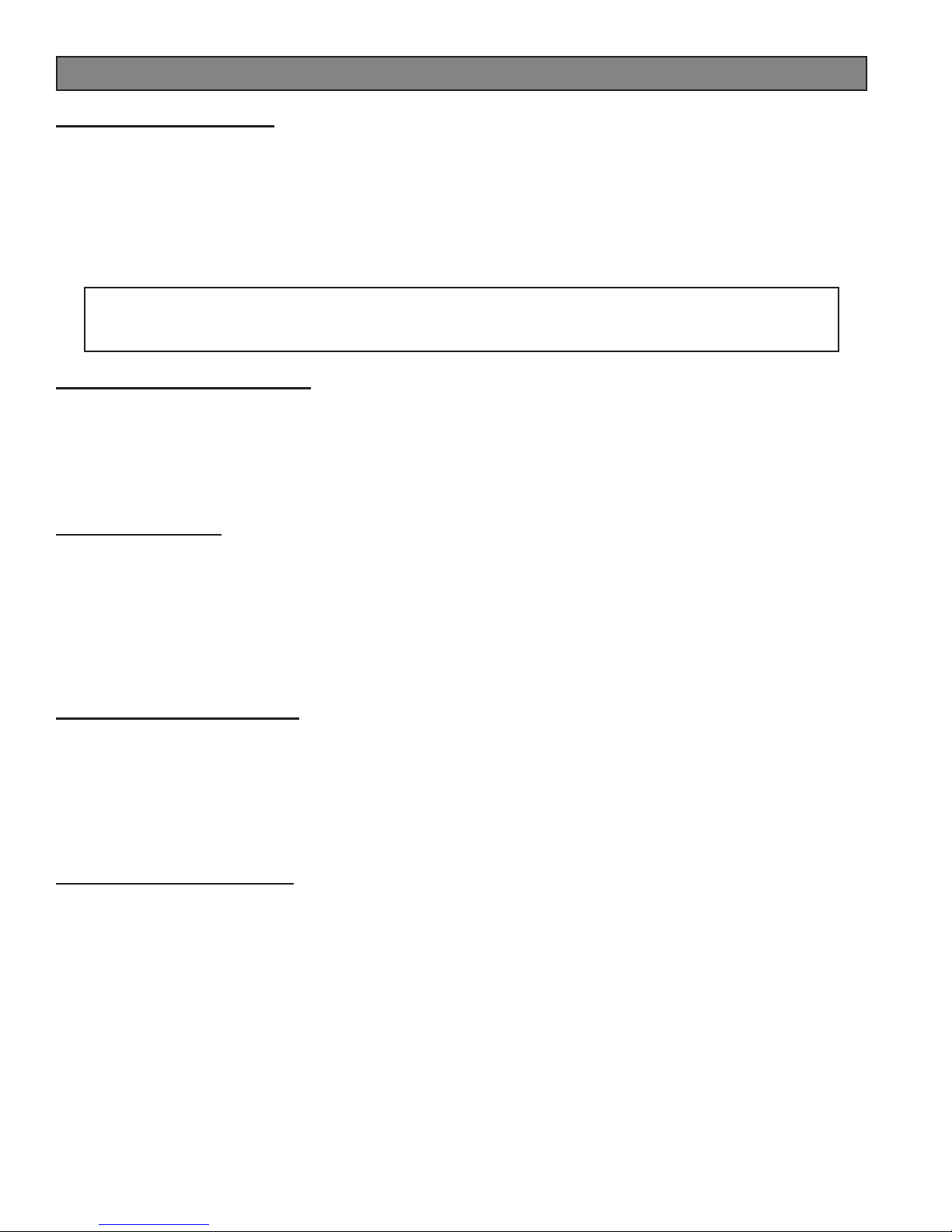
VENT TERMINATION CLEARANCES:
A) Minimum 4-foot (1.22m) clearance below or beside any door or window that opens.
B) Minimum 1-foot (0.3m) clearance above any door or window that opens.
C) Minimum 3-foot (0.91m) clearance from any adjacent building.
D) Minimum 7-foot (2.13m) clearance from any grade when adjacent to public walkways.
E) Minimum 2-foot (0.61m) clearance above any grass, plants, or other combustible materials.
F) Minimum 3-foot (0.91m) clearance from an forced air intake of any appliance.
G) Minimum 2-foot (0.61m) clearance below eves or overhang.
H) Minimum 1-foot (0.3m) clearance horizontally from combustible wall.
I) Must be a minimum of 3 foot (0.91m) above the roof and 2 foot (0.61m) above the highest point or the roof within
10 feet (3.05m).
G
VENT TERMINATION CLEARANCES
FIGURE 6
7
Installation
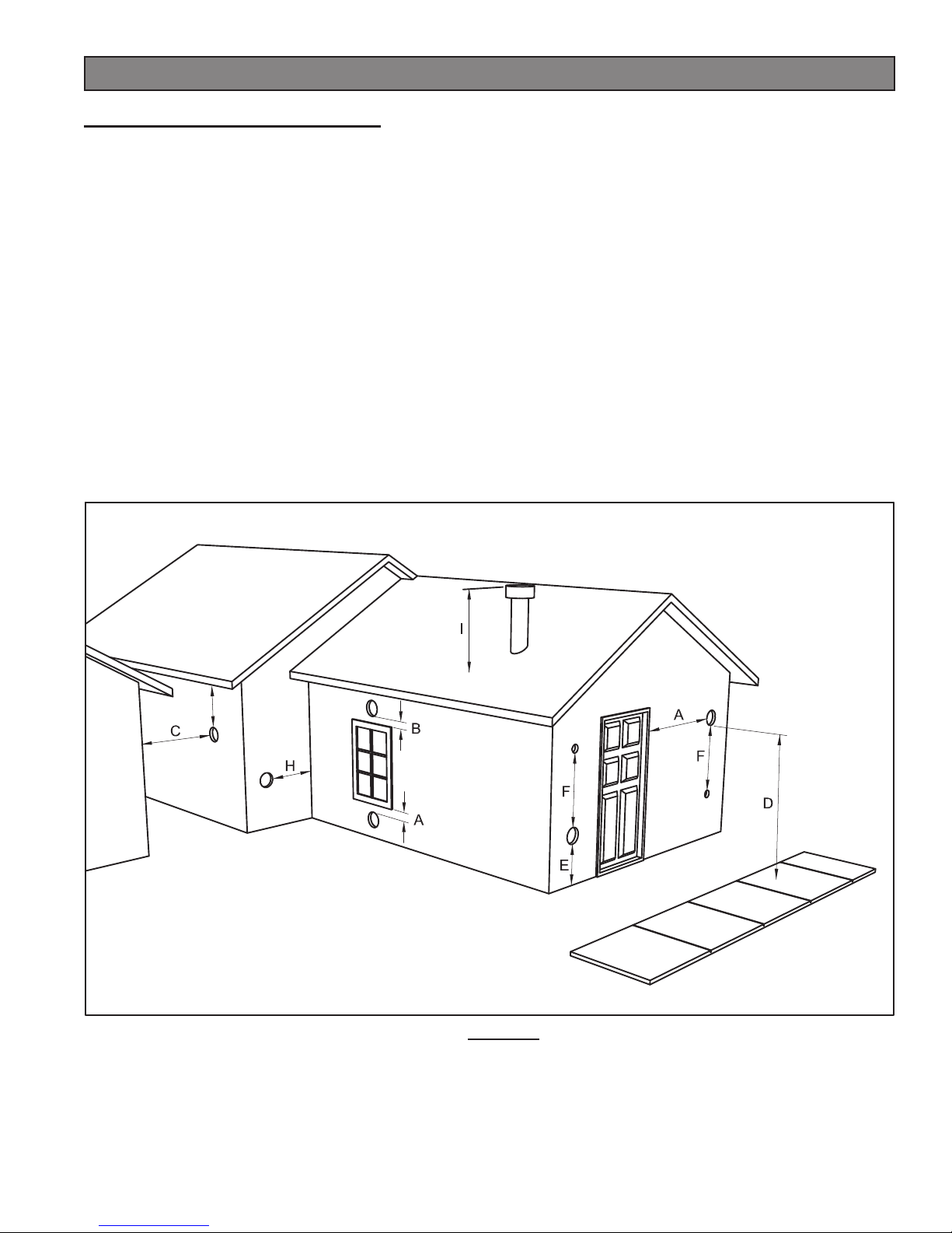
THROUGH THE WALL INSTALLATION (RECOMMENDED INSTALLATION)
Canadian installations must conform to CAN/CSA-B365.
To vent the unit through the wall, connect the pipe adapter
to the exhaust motor adapter. If the exhaust adapter is at
least 24 in.(609mm) above ground level, a straight section
of pellet vent pipe can be used through the wall.
Your heater dealer should be able to provide you with
a kit that will handle most of this installation, which will
include a wall thimble that will allow the proper clearance
through a combustible wall. Once outside the structure,
a 3 in.(76mm) clearance should be maintained from the
outside wall and a clean out tee should be placed on the
pipe with a 90-degree turn away from the house. The Clean
out tee must be placed at the bottom of the vertical section
of venting, NOT in the horizontal section. At this point, a 3ft
(0.91m) (minimum) section of pipe should be added with
a horizontal cap, which would complete the installation
(see FIGURE 7).
A support bracket should be placed just below the
termination cap or one every 4ft (1.22m) to make the
system more stable. If you live in an area that has heavy
snowfall, it is recommended that the installation be taller
than 3ft (0.91m) to get above the snowdrift line. This same
installation can be used if your heater is below ground level
by simply adding the clean-out section and vertical pipe
inside until ground level is reached. With this installation
you have to be aware of the snowdrift line, dead grass, and
leaves. We recommend a 3ft (0.91m) minimum vertical
rise on the inside or outside of the house.
TYPICAL THROUGH THE WALL INSTALLATION
FIGURE 7
The “through the wall” installation is the least expensive and simplest installation. Never terminate the vent under a
deck, in an alcove, under a window, or between two windows. We recommend Simpson Dura-Vent® or Metal-Fab® kits.
THROUGH THE ROOF/CEILING INSTALLATION
When venting the heater through the ceiling, the pipe is connected the same as through the wall, except the clean-out
tee is always on the inside of the house, and a 3 in.(76mm) adapter is added before the clean-out tee. The Clean out
tee must be placed at the bottom of the vertical section of venting, NOT in the horizontal section.
You must use the proper ceiling support fl anges and roof fl ashing (supplied by the pipe manufacturer; follow the pipe
manufacturer’s directions). It is important to note that if your vertical run of pipe is more than 12ft (3.7m), the pellet vent
pipe size should be increased to 4 in. (102mm) in diameter coming from the back of the stove.
Do not exceed more than 4ft (1.22m) of pipe on a horizontal run and use as few elbows as possible. If an offset is
required, it is better to install 45-degree elbows rather than 90-degree elbows.
8
Installation
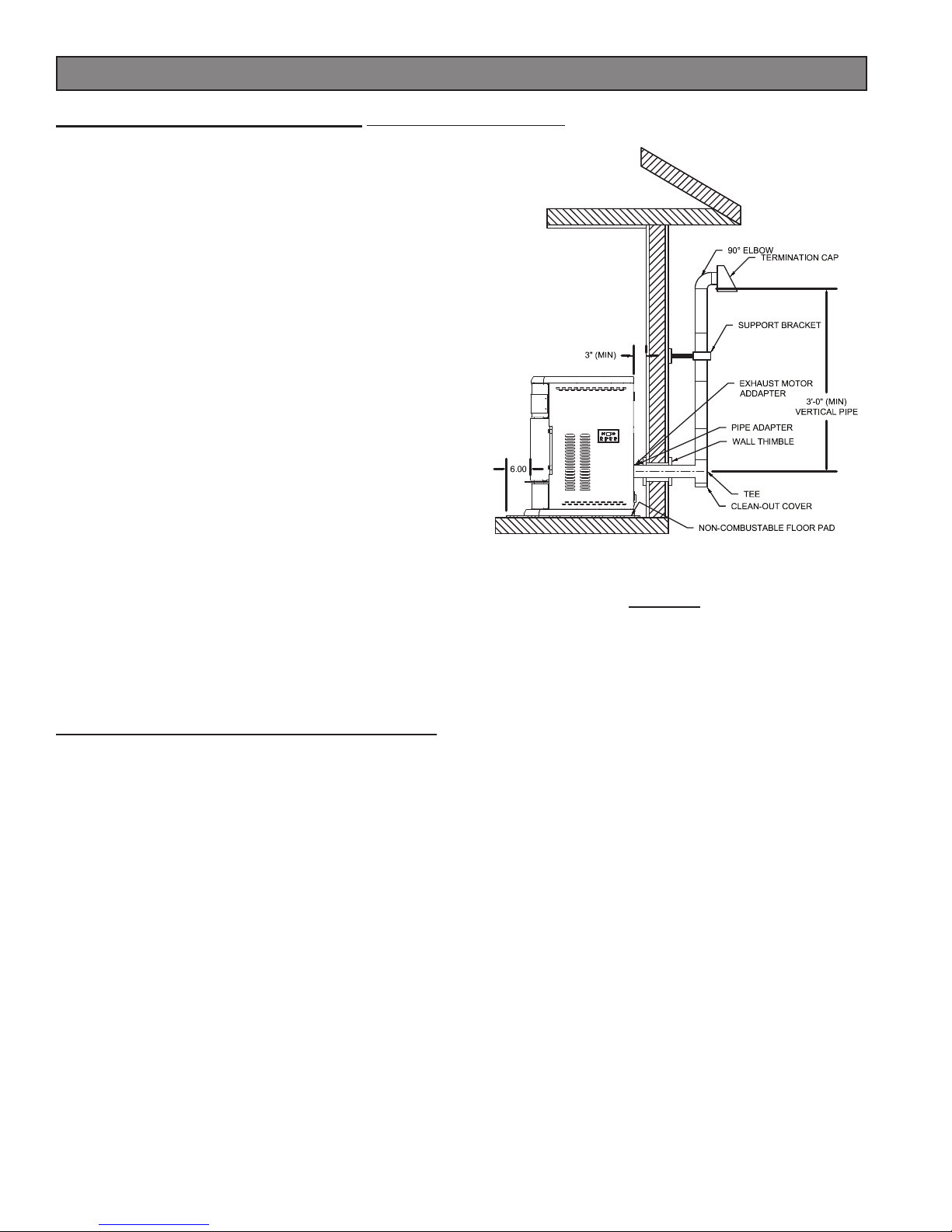
OUTSIDE AIR SUPPLY (optional, unless installing in a mobile home)
Adequate ventilation air is required to operate this heater. During operation, the heater draws air for combustion which
can be assisted by the installation of outside combustion air inlets. However, certain weather conditions such as icing
or use of kitchen exhaust fans may impact and reduce the effectiveness of vents. It is important to note that room air
starvation will negatively impact the operation of the heater.
Depending on your location and home construction, outside air may be necessary for optimal performance.
Metal pipe (solid or fl exible) must be used for the outside air installation. PVC pipe is NOT approved and should NEVER
be used.
A wind shield over the termination of the outside air pipe or a 90-degree elbow or bend away from the prevailing winds
MUST be used when an outside air pipe is installed through the side of a building. The outside air termination MUST
be at least 1ft (0.305m) away from the exhaust system termination.
The outside air pipe on your heater is 2” (50.8mm) OD. The outside air connecting pipe must be at least 2” (50.8mm) ID.
The outside air connection used MUST NOT restrict the amount of air available to your heater. The outside air connecting
pipe must be as short and free of bends as possible, and it must fi t over, not inside, the outside air connection to the heater.
TYPICAL FRESH AIR TERMINATION
NOTE: Dimensions from the fl oor to your stoves
inlet/exhaust pipes are approximate and may vary
depending on your installation.
FIGURE 9
SPECIAL MOBILE HOME REQUIREMENTS
WARNING! - DO NOT INSTALL IN A SLEEPING ROOM.
CAUTION! - THE STRUCTURAL INTEGRITY OF THE MOBILE HOME FLOOR, WALL, AND CEILING/ROOF
MUST BE MAINTAINED.
In addition to the previously detailed installation requirements, mobile
home installations must meet the following requirements:
• The unit must be secured to the fl oor using lag bolts in the holes
provided in the pedestal base.
• The heater must be electrically grounded to the steel chassis
of the mobile home with 8 GA copper wire using a serrated or
star washer to penetrate paint or protective coating to ensure
grounding.
• Vent must be 3 or 4-inch “PL” Vent and must extend a minimum
or 36 in.(914mm) above the roof line of the mobile home and
must be installed using a UL listed ceiling fi re stop and rain cap.
• When moving your mobile home, all exterior venting must
be removed while the mobile home is being relocated. After
relocation, all venting must be reinstalled and securely fastened.
• Outside Air is mandatory for mobile home installation. See
Outside Air Supply section and your dealer for purchasing.
• Check with your local building offi cials as other codes may
apply.
Mobile Home Mounting
Bolt Hole
Mobile Home
Mounting Bolt Hole
9
 Loading...