

Vogelzang International VG5770, VG5770I Owner's Manual
MODEL: VG5770/VG5770I
Certifi ed for installations in the USA
and Canada.
U.S. Environmental Protection Agency
Certified to comply with 2015 particulate
emissions standards.
French version is available for download from the Vogelzang website: http://www.usstove.com/
Version française est disponible pour téléchargement à partir du site Vogelzang: http://www.usstove.com
OWNER’S MANUAL
This unit is not intended to be used as a primary source of heat.
PLEASE READ THIS ENTIRE MANUAL BEFORE INSTALLATION AND USE OF THIS APPLIANCE.
FAILURE TO FOLLOW THESE INSTRUCTIONS COULD RESULT IN PROPERTY DAMAGE, BODILY
INJURY, OR EVEN DEATH.
CONTACT YOUR LOCAL BUILDING OR FIRE OFFICIALS ABOUT OBTAINING PERMITS, RE-
STRICTIONS AND INSTALLATION INSPECTION REQUIREMENTS IN YOUR AREA.
SAVE THESE INSTRUCTIONS.
U.S. Stove Company
227 Industrial Park Road, South Pittsburg, TN 37380
FOR TECHNICAL ASSISTANCE: Phone 800-750-2723 www.usstove.com
852050D-1903E

Safety Precautions
This manual describes the installation and operation of the Vogelzang, VG5770, VG5770I wood heater. This heater meets the 2015
U.S. Environmental Protection Agency’s crib wood emission limits for wood heaters sold after May 15, 2015. Under specifi c test
conditions this heater has been shown to deliver heat at rates ranging from 10,898 to 24,335 Btu/hr.
IMPORTANT: Read this entire manual before installing and
operating this product. Failure to do so may result in property
damage, bodily injury, or even death. Proper installation of
this stove is crucial for safe and efficient operation.
Install vent at clearances specified by the vent manufacturer.
Do not connect the pellet vent to a vent serving any other
appliance or stove.
Do not install a flue damper in the exhaust venting system
of this unit.
Use of outside air is not required for this unit.
Contact your local building officials to obtain a permit and
information on any additional installation restrictions or inspection requirements in your area.
Do not throw this manual away. This manual has important
operating and maintenance instructions that you will need at
a later time. Always follow the instructions in this manual.
This appliance is designed for the use of pelletized fuel
that meet or exceed the standard set by the Pellet Fuel
Institute(PFI), The use of other fuels will void warranty.
Never use gasoline, gasoline-type lantern fuel, kerosene,
charcoal lighter fluid, or similar liquids to start or ’freshen up’
a fire in this stove. Keep all such liquids well away from the
stove while it is in use.
A working smoke detector must be installed in the same room
as this product.
Install a smoke detector on each floor of your home; incase of
accidental fire from any cause it can provide time for escape.
The smoke detector must be installed at least 15 feet (4,57
M) from the appliance in order to prevent undue triggering of
the detector when reloading.
Do not unplug the stove if you suspect a malfunction. Turn
the ON/OFF SWITCH to ”OFF’ and contact your dealer.
Your stove requires periodic maintenance and cleaning (see
”MAINTENANCE ”). Failure to maintain your stove may lead
to improper and/or unsafe operation.
Disconnect the power cord before performing any mainte-
nance! NOTE: Turning the ON/OFF Switch to ”OFF” does not
disconnect all power to the electrical components of the stove.
Never try to repair or replace any part of the stove unless
instructions for doing so are given in this manual. All other
work should be done by a trained technician.
Do not operate your stove with the viewing door open. The
auger will not feed pellets under these circumstances and
a safety concern may arise from sparks or fumes entering
the room.
Allow the stove to cool before performing any maintenance or
cleaning. Ashes must be disposed in a metal container with
a tight fitting lid. The closed container of ashes should be
placed on a non-combustible surface or on the ground, well
away from all combustible materials, pending final disposal.
The exhaust system should be checked monthly during the
burning season for any build-up of soot or creosote.
Do not touch the hot surfaces of the stove. Educate all
children on the dangers of a high-temperature stove. Young
children should be supervised when they are in the same
room as the stove.
The hopper and stove top will be hot during operation; there-
fore, you should always use some type of hand protection
when refueling your stove.
A power surge protector is required. This unit must be plugged
into a 110 - 120V, 60 Hz grounded electrical outlet. Do not
use an adapter plug or sever the grounding plug. Do not route
the electrical cord underneath, in front of, or over the heater.
Do not route the cord in foot traffic areas or pinch the cord
under furniture.
The heater will not operate during a power outage. If a power
outage does occur, check the heater for smoke spillage and
open a window if any smoke spills into the room.
The feed door must be closed and sealed during operation.
Never block free airflow through the open vents of the unit.
Keep foreign objects out of the hopper.
The moving parts of this stove are propelled by high torque
electric motors. Keep all body parts away from the auger
while the stove is plugged into an electrical outlet. These
moving parts may begin to move at any time while the stove
is plugged in.
Do not place clothing or other flammable items on or near
this stove.
When installed in a mobile home, the stove must be grounded
directly to the steel chassis and bolted to the floor. WARNING—THIS UNIT MUST NOT BE INSTALLED IN THE BEDROOM (per HUD requirements). CAUTION—THE STRUCTURAL INTEGRITY OF THE MOBILE HOME FLOOR, WALL,
AND CEILING/ROOF MUST BE MAINTAINED.
This appliance is not intended for commercial use.
CAUTION: Burning fuel creates carbon monoxide and can be
hazardous to your health if not properly vented.
* This appliance is a freestanding heater. It is not intended to be attached to any type of ducting. It is not a furnace.
2
WARRANTY INFORMATION CARD
Name__________________________________________ Telephone #: (_____)_____________
City____________________________________________ State_______ Zip_________________
Email Address __________________________________________________________________
Model # of Unit________________________________ Serial #___________________________
Fuel Type:
Wood Coal Pellet Gas Other _________________________
Place of Purchase (Retailer)______________________________________________________
City____________________________________________ State_______ Zip_________________
If internet purchase, please list website address___________________________________
Date of Purchase _______________________________________________________________
Reason for Purchase: Alternative Heat Main Heat Source
Decoration Cost Other _________________________
What was the determining factor for purchasing your new USSC appliance?_______
I have read the owner’s manual that accompanies this unit and fully understand the:
Installation
Operation and Maintenance of my new USSC appliance.
Print Name Signature Date
Please attach a copy of your purchase receipt.
Warranty not valid without a Proof of Purchase.
Warranty information must be received within 30 days of original purchase.
Detach this page from this manual, fold in half with this page to the inside and tape together. Apply a
stamp and mail to the address provided. You may use an envelope if you choose.
You may register online by going to www.usstove.com
All information submitted will be kept strictly con dential. Information provided will not be sold for advertising purposes.
Contact information will be used solely for the purpose of product noti cations.
CUT HERE CUT HERE

Fold Here Fold Here
Fold Here
PLACE
STAMP
HERE
United States Stove Company
P.O. Box 151
South Pittsburg, TN 37380
CUT HERE CUT HERE
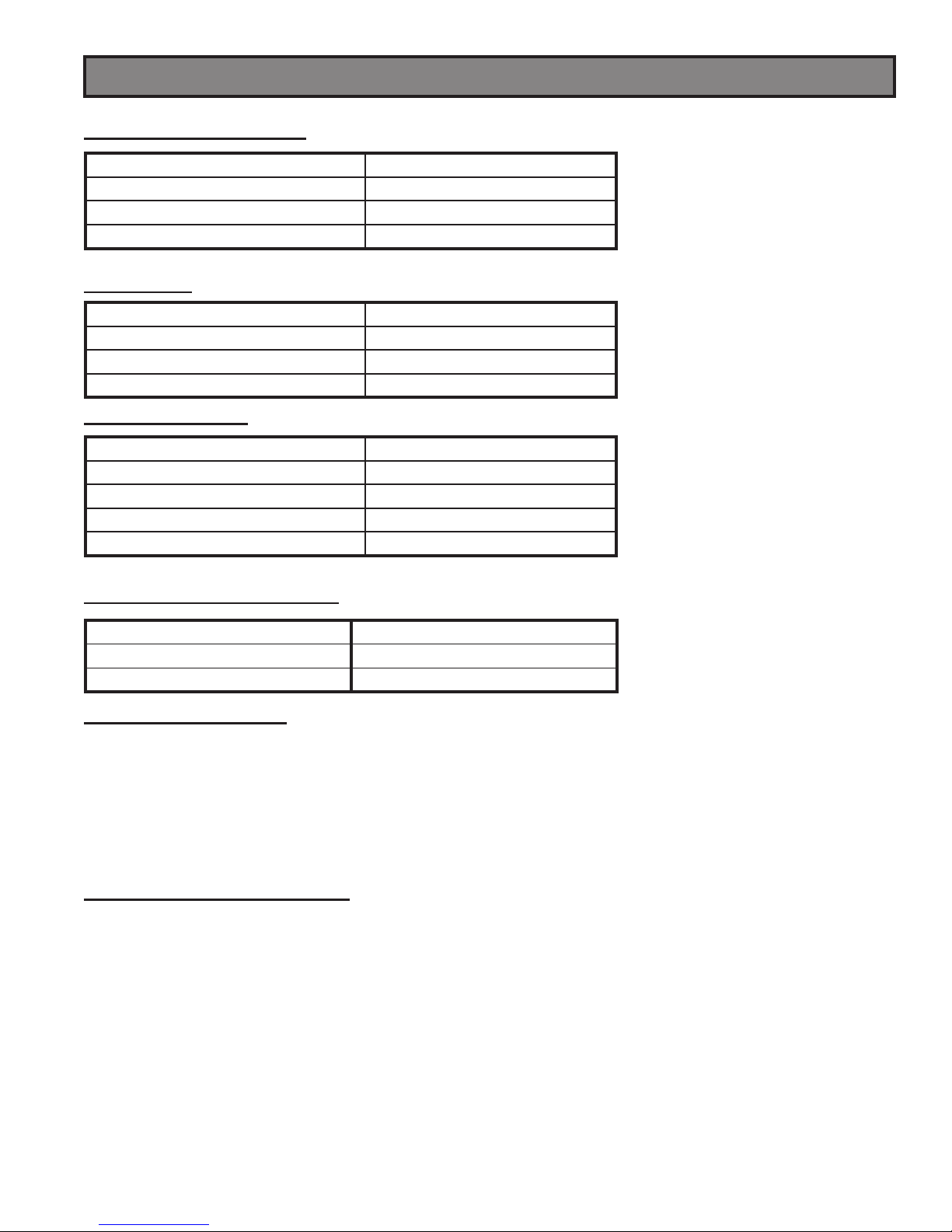
SPECIFICATIONS
HEATING SPECIFICATIONS
Fuel Burn Rate* (lowest setting) 1.5 lbs./hr. (0.5 kg/hr)
Burn Time (lowest setting) 40 hrs. (approximate)
Hopper Capacity 60 lbs. (55kg)
BTU up to 48,000
* Pellet size may effect the actual rate of fuel feed and burn times. Fuel feed rates may vary by as much as 20%. Use PFI listed fuel for best results.
DIMENSIONS
Height 44.5 in. (1130mm)
Width 23 in. (584mm)
Depth 23.5 in. (597mm)
Weight 245 lbs. (111.1kg)
FIREPLACE INSERT
Height 24” (With Flashing: 32”)
Width 22” (With Flashing: 44”)
Depth 8.5”
Weight 182.5 Lbs. (Flashing 15.5 Lbs)
Flue Size 3” to 4”
* Approved installations: zer0-clearance, masonry, as a built-in.
ELECTRICAL SPECIFICATIONS
Electrical Rating 110-120 volts, 60 HZ, 3.0 Amps
Watts (operational) 180
Watts (igniter running) 346
FUEL CONSIDERATIONS
Your pellet stove is designed to burn premium hardwood pellets that comply with Association of Pellet Fuel Industries
standards. (Minimum of 40 lbs density per cubic ft, 1/4” to 5/16” diameter, length no greater than 1.5”, not less than
8,200 BTU/lb, moisture under 8% by weight, ash under 1% by weight, and salt under 300 parts per million). Pellets
that are soft, contain excessive amounts of loose sawdust, have been, or are wet, will result in reduced performance.
Store your pellets in a dry place. DO NOT store the fuel within the installation clearances of the unit or within the space
required for refueling and ash removal. Doing so could result in a house fi re.
Do not over fi re or use volatile fuels or combustibles, doing so may cause a personal and property damage hazards.
SAFETY AND EPA COMPLIANCE
Your pellet stove has been approved for installation in the USA and Canada. It may also be installed in a
manufactured or mobile home. Your stove conforms to ASTM E 1509, and Certifi ed to ULC S627, and(UM) 84-HUD
by INTERTEK Testing Services in Fairview, Oregon USA.
5
INSTALLATION
INSTALLATION OPTIONS
Read this entire manual before you install and use your pellet stove. Failure to follow instructions may result
in property damage, bodily injury, or even death!
(See specifi c installation details for clearances and other installation requirements)
A Freestanding Unit—supported by pedestal/legs and placed on a non-combustible fl oor surface in compliance with
clearance requirements for a freestanding stove installation.
An Alcove Unit—supported by pedestal/legs and placed on a non-combustible fl oor surface in compliance with clearance
requirements for an alcove installation.
An Insert Unit— is inserted directly into an existing fi re place.
Your pellet stove may be installed to code in either a conventional or mobile home (see SPECIAL MOBILE HOME REQUIREMENTS). The installation must comply with the Manufactured Home and Safety Standard (HUD), CFR3280, Part
24.
It is recommended that only a authorized technician install your pellet stove, preferably an NFI certifi ed specialist.
DO NOT CONNECT THIS UNIT TO ANY AIR DISTRIBUTION DUCT OR SYSTEM.
The use of other components other than stated herein could cause bodily harm, heater damage, and void your warranty.
IMPROPER INSTALLATION: The manufacturer will not be held responsible for damage caused by the malfunction of a stove due to improper venting or installation. Call (800) 750-2723 and/or consult a professional
installer if you have any questions.
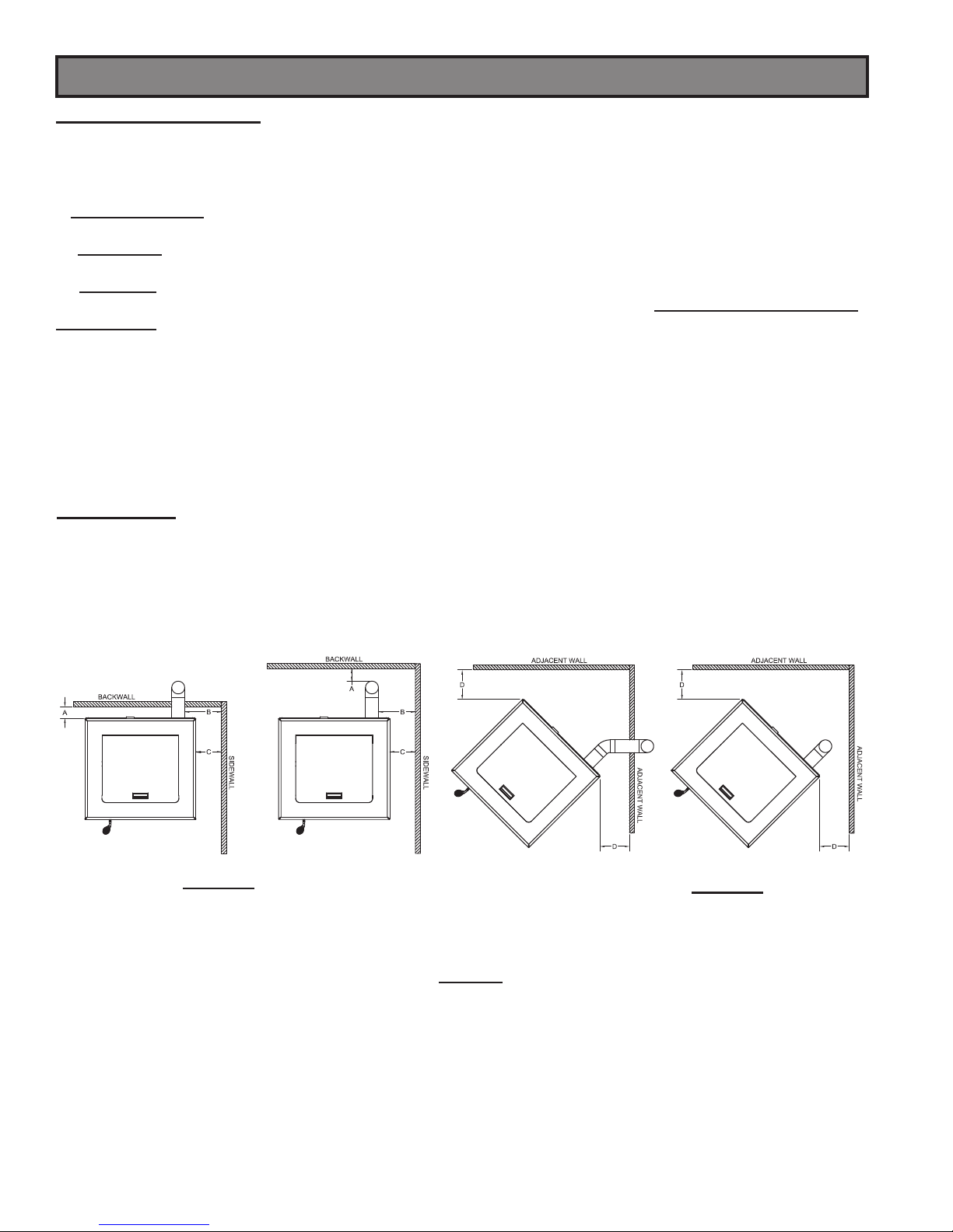
CLEARANCES
Your pellet stove has been tested and listed for installation in residential, mobile home, and alcove applications in
accordance with the clearances given in FIGURES 1-2 and TABLE 1. For safety reasons, please adhere to the installation
clearances and restrictions. Any reduction in clearance to combustibles may only be done by means approved by a
regulatory authority.
FIGURE 1
SIDEWALL CLEARANCES
PARALLEL INSTALLATION
PARALLEL A - Backwall to unit 3.00 / 76mm
B - Sidewall to fl ue 11.00 / 280mm
C - Sidewall to top edge of unit 8.00 / 203mm
CORNER D - Adjacent wall to unit 8.00 / 203mm
6
FIGURE 2
SIDEWALL CLEARANCES
CORNER INSTALLATION
TABLE 1
CLEARANCES
INSTALLATION
U.S. 6.00
Canada 450mm (18”)
U.S. 6.00
Canada 450mm (18”)
U.S. 6.00
Canada
203mm (8”)
U.S. 6.00
Canada
203mm (8”)
U.S. 6.00
Canada
203mm (8”)
U.S. 6.00
Canada
203mm (8”)
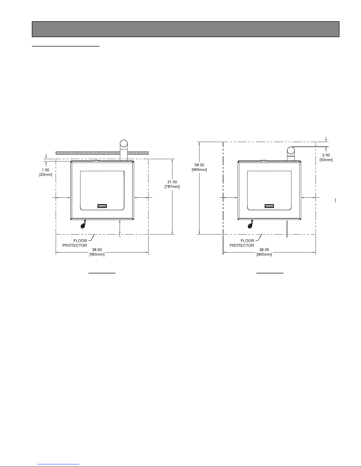
FLOOR PROTECTION
This heater must have a non-combustible fl oor protector (UL1618 ember protection) installed beneath it if the fl oor is of
combustible material. The fl oor pad or non-combustible surface should be large enough to cover at least the area under
the product and 6 in. (152 mm) beyond the front and beyond each side of the fuel loading and ash removal openings.
Your heater will need a minimum 31” X 38” fl oor protector. Floor protection must extend under and 2 in. (50.8 mm) to
each side of the chimney tee for an interior vertical installation (see FIGURE 4) This applies to both freestanding heaters
and insert heaters.
Canadian Installations require a minimum of 475 mm [18”] beyond the front of the unit and 203 mm [8”] beyond each
side of the unit. A Floor Protector of 1/4 inch thick is recommended for this installation.
THROUGH THE WALL INSTALLATION
FIGURE 3
INTERIOR VERTICAL INSTALLATION
FIGURE 4
7
5.72
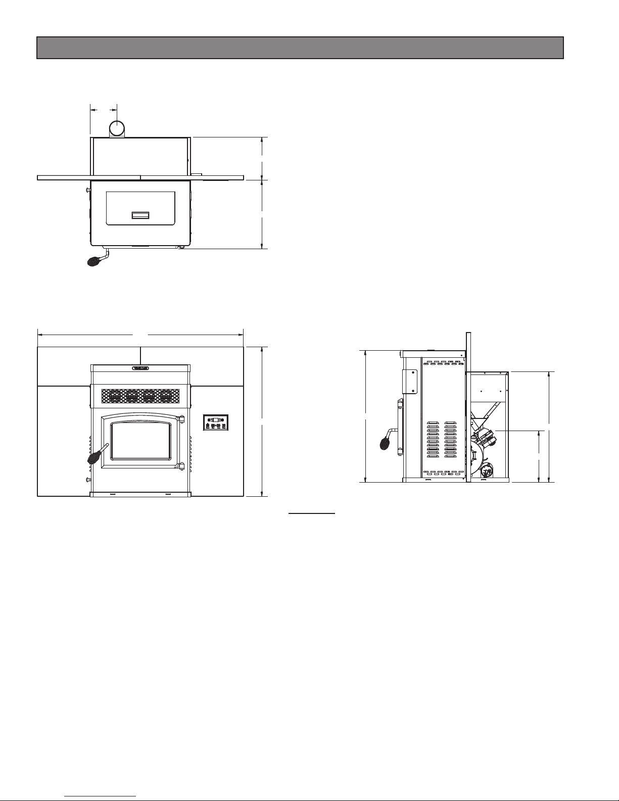
INSTALLATION
The minimum installation dimensions, of the insert opening, are:
22” (558.8 mm) wide x 24” (609.6 mm) high x 9.17” (233 mm) deep.
9.17
14.59
43.93
31.92
FIGURE 5
INSERT DIMENSIONS
28.17
23.60
11.00
8

INSTALLATION
VENTING REQUIREMENTS
Install vent at clearances specified by the vent manufacturer.
Do not connect the pellet vent to a vent serving any other appliance or stove.
Do not install a flue damper in the exhaust venting system of this unit.
The following installation guidelines must be followed to ensure conformity with both the safety listing of this stove and
to local building codes. Do not use makeshift methods or compromise in the installation.
IMPORTANT! This unit is equipped with a negative draft system that pulls air through the burn pot and
pushes the exhaust out of the dwelling. If this unit is connected to a fl ue system other than the way ex-
plained in this manual, it will not function properly.
MAXIMUM VENTING DISTANCE
Installation MUST include at least 3-feet of vertical pipe outside the home. This will create some natural draft to reduce the
possibility of smoke or odor during appliance shutdown and keep exhaust from causing a nuisance or hazard by exposing
people or shrubs to high temperatures. The maximum recommend vertical venting height is 12-feet for 3-inch type “PL”
vent. Total length of horizontal vent MUST NOT exceed 4-feet. This could cause back pressure. Use no more than 180
degrees of elbows (two 90-degree elbows, or two 45-degree and one 90-degree elbow, etc.) to maintain adequate draft.
IMPORTANCE OF PROPER DRAFT
Draft is the force which moves air from the appliance up through the chimney. The amount of draft in your chimney
depends on the length of the chimney, local geography, nearby obstructions and other factors. Too much draft may
cause excessive temperatures in the appliance. Inadequate draft may cause backpuffi ng into the room and ‘plugging’
of the chimney.
Inadequate draft will cause the appliance to leak smoke into the room through appliance and chimney connector joints.
An uncontrollable burn or excessive temperature indicates excessive draft.
Take into account the chimney’s location to insure it is not too close to neighbors or in a valley which may cause unhealthy
or nuisance conditions.
PELLET VENT TYPE
A UL listed 3-inch or 4-inch type “PL” pellet vent exhaust system must be used for installation and attached to the pipe
connector provided on the back of the stove (use a 3-inch to 4-inch adapter for 4-inch pipe). Connection at back of
stove must be sealed using Hi-Temp RTV. Use 4-inch vent if the vent height is over 12-feet or if the installation is over
2,500 feet above sea level.
We recommend the use of Simpson Dura-Vent® or Metal-Fab® pipe (if you use other pipe, consult your local building
codes and/or building inspectors). Do not use Type-B Gas Vent pipe or galvanized pipe with this unit. The pellet vent
pipe is designed to disassemble for cleaning and should be checked several times during the burning season. Pellet
vent pipe is not furnished with the unit and must be purchased separately.
PELLET VENT INSTALLATION
The installation must include a clean-out tee to enable collection of fl y ash and to permit periodic cleaning of the exhaust
system. 90-degree elbows accumulate fl y ash and soot thereby reducing exhaust fl ow and performance of the stove.
Each elbow or tee reduces draft potential by 30% to 50%.
All joints in the vent system must be fastened by at least 3 screws, and all joints must be sealed with Hi-Temp RTV
silicone sealant to be airtight. The area where the vent pipe penetrates to the exterior of the home must be sealed with
silicone or other means to maintain the vapor barrier between the exterior and the interior of the home.
Vent surfaces can get hot enough to cause burns if touched by children. Noncombustible shielding or guards may be
required.
PELLET VENT TERMINATION
Do not terminate the vent in an enclosed or semi-enclosed area, such as; carport, garage, attic, crawl space, under
a sundeck or porch, narrow walkway, or any other location that can build up a concentration of fumes. Termination in
one of these areas can also lead to unpredictable pressure situations with the appliance, and could result in improper
performance and/or malfunction
The termination must exhaust above the outside air inlet elevation.
The termination must not be located where it will become plugged by snow or other materials.
Do not terminate the venting into an existing steel or masonry chimney.
9
INSTALLATION
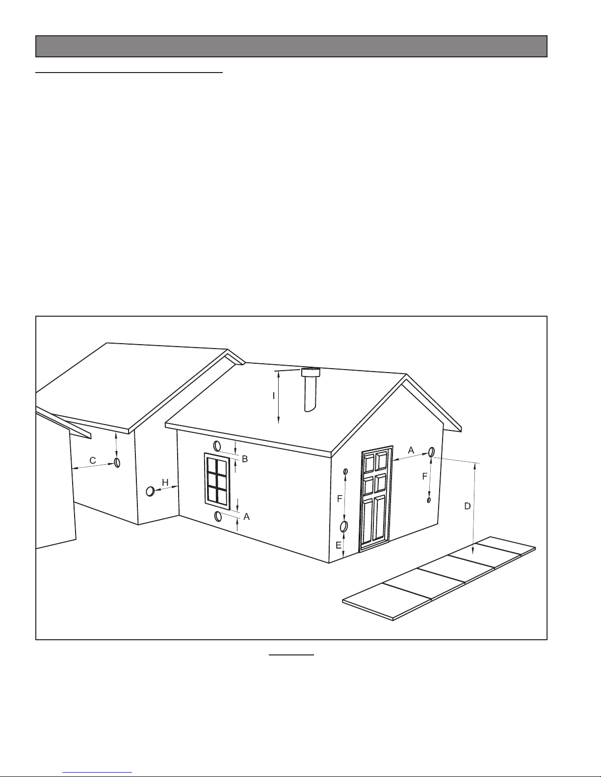
VENT TERMINATION CLEARANCES:
A) Minimum 4-foot (1.22m) clearance below or beside any door or window that opens.
B) Minimum 1-foot (0.3m) clearance above any door or window that opens.
C) Minimum 3-foot (0.91m) clearance from any adjacent building.
D) Minimum 7-foot (2.13m) clearance from any grade when adjacent to public walkways.
E) Minimum 2-foot (0.61m) clearance above any grass, plants, or other combustible materials.
F) Minimum 3-foot (0.91m) clearance from an forced air intake of any appliance.
G) Minimum 2-foot (0.61m) clearance below eves or overhang.
H) Minimum 1-foot (0.3m) clearance horizontally from combustible wall.
I) Must be a minimum of 3 foot (0.91m) above the roof and 2 foot (0.61m) above the highest point or the roof within
10 feet (3.05m).
G
VENT TERMINATION CLEARANCES
FIGURE 6
10
INSTALLATION
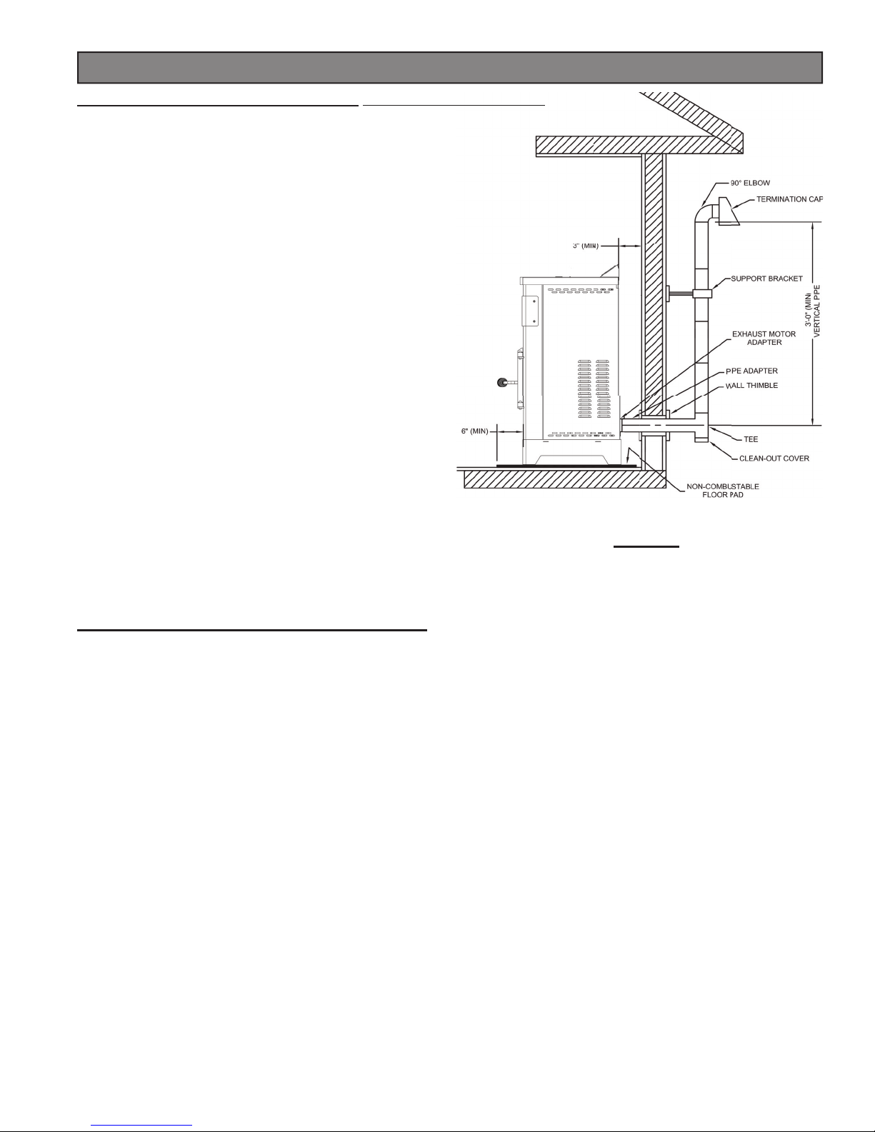
THROUGH THE WALL INSTALLATION (RECOMMENDED INSTALLATION)
Canadian installations must conform to CAN/CSA-B365.
To vent the unit through the wall, connect the pipe adapter
to the exhaust motor adapter. If the exhaust adapter is at
least 18 in.(457mm) above ground level, a straight section
of pellet vent pipe can be used through the wall.
Your heater dealer should be able to provide you with
a kit that will handle most of this installation, which will
include a wall thimble that will allow the proper clearance
through a combustible wall. Once outside the structure,
a 3 in.(76mm) clearance should be maintained from the
outside wall and a clean out tee should be placed on the
pipe with a 90-degree turn away from the house. At this
point, a 3ft (0.91m) (minimum) section of pipe should be
added with a horizontal cap, which would complete the
installation (see FIGURE 7).
A support bracket should be placed just below the
termination cap or one every 4ft (1.22m) to make the
system more stable. If you live in an area that has heavy
snowfall, it is recommended that the installation be taller
than 3ft (0.91m) to get above the snowdrift line. This same
installation can be used if your heater is below ground level
by simply adding the clean-out section and vertical pipe
inside until ground level is reached. With this installation
you have to be aware of the snowdrift line, dead grass, and
leaves. We recommend a 3ft (0.91m) minimum vertical
rise on the inside or outside of the house.
TYPICAL THROUGH THE WALL INSTALLATION
FIGURE 7
The “through the wall” installation is the least expensive and simplest installation. Never terminate the end vent under a
deck, in an alcove, under a window, or between two windows. We recommend Simpson Dura-Vent® or Metal-Fab® kits.
THROUGH THE ROOF/CEILING INSTALLATION
When venting the heater through the ceiling, the pipe is connected the same as through the wall, except the clean-out
tee is always on the inside of the house, and a 3 in.(76mm) adapter is added before the clean-out tee.
You must use the proper ceiling support fl anges and roof fl ashing (supplied by the pipe manufacturer; follow the pipe
manufacturer’s directions). It is important to note that if your vertical run of pipe is more than 12ft (3.7m), the pellet vent
pipe size should be increased to 4 in. (102mm) in diameter.
Do not exceed more than 4ft (1.22m) of pipe on a horizontal run and use as few elbows as possible. If an offset is
required, it is better to install 45-degree elbows rather than 90-degree elbows.
11
 Loading...