

Vogelzang International VG1500, VG2500 Owner's Manual
Models VG1500/VG2500
OWNER'S MANUAL
SOLID FUEL
WARM AIR FURNACE
FOR PARALLEL INSTALLATION WITH EXISTING FORCED AIR-GAS OR OIL
FIRED FURNACE (U.S. ONLY)
FOR INSTALLATION AS A CENTRAL FURNACE
THE VG2500 FURNACE HAS BEEN APPROVED FOR U.S. INSTALLATIONS
ONLY.
ALL MODELS CERTIFIED UNDER UL 391-2010
MODELS VG1500 IS ALSO CERTIFIED UNDER CSA-B366.1-11
SAVE THESE INSTRUCTIONS
CAUTION:
READ ALL INSTRUCTIONS CAREFULLY BEFORE STARTING THE
INSTALLATION OR OPERATING
THE FURNACE
IMPROPER INSTALLATION MAY
VOID YOUR WARRANTY
DO NOT USE THIS FURNACE
IN A MOBILE HOME OR TRAILER
UNITED STATES STOVE COMPANY
227 Industrial Park Road
South PIttsburg, TN 37380
PH.: (800) 750-2723 • www.Vogelzang.com
LISTED BY LISTED BY
OMNI-Test Laboratories, Inc.
Report Number 215-S-07c-4
VG2500 (Certied for US only)
PORTLAND,
OREGON, USA
PORTLAND,
OREGON, USA
OMNI-Test Laboratories, Inc.
Report Number 215-S-07c-4
VG1500 (Certied for US and Canada)
852057

CONGRATULATIONS!
You've purchased one of America's Finest Wood and Coal
Burning Furnaces. By heating with wood and coal you're
helping CONSERVE AMERICA'S ENERGY! Wood is our
Renewable Energy Resource. Please do your part to preserve our wood supply. Plant at least one tree each year.
Future generations will thank you.
NOTE: YOUR UNIT MUST BE INSTALLED BY A
QUALIFIED FURNACE INSTALLER.
TOOLS AND MATERIALS NEEDED
TOOLS
Pencil
6 Foot Folding Rule or Tape
Tin Snips
Drill, Hand or Electric
Drill Bit- 1/8" Dia.
(For Sheet Metal Screws)
Screw Driver (Blade-Type)
Gloves
Sabre Saw
5/16" Nut Driver or
5/16" Socket w/Ratchet
Safety Glasses
6" Pipe, 6" Elbow, Collar and Thimble;
as required (24 gauge min.)
1/2" Sheet Metal Screws
6" Inside diameter Listed Residential
Type or Building Heating Appliance
Chimney or existing masonry chimney
Electrical Wiring
6" Draft Regulator
1/2" Conduit (Conduit Connectors)
Furnace Cement (Manufacturer
Recommends: Rutland Black-Code 78
or Equivalent)
Plenum and Duct work as required.
MATERIAL
2
Caution Labels
Your Furnace has the following labels. Read and Obey all labels.
DANGER: RISK OF FIRE OR EXPLOSION.
DO NOT burn garbage, gasoline, drain oil, or other ammable liquids.
WARNING: FIRE HAZARD.
DO NOT operate with re draft exceeding .06 inches w.c.
DO NOT operate with fuel loading or ash removal doors open.
DO NOT store fuels, paints, thinners, ammable liquids, or other highly volatile sub-
stances in the furnace room.
CAUTION:
HOT SURFACES! Keep children away. Do not touch during operation.
CAUTION!
INSPECT FLUE PIPES, FLUE PIPE JOINTS AND FLUE PIPE SEALS
REGULARLY TO ENSURE THAT SMOKE AND FLUE GASES ARE NOT
DRAWN INTO, AND CIRCULATED BY, THE AIR CIRCULATION SYSTEM.
CAUTION!
CLEANOUT OF THE HEAT EXCHANGER, FLUE PIPE, CHIMNEY, AND
DRAFT INDUCER (IF USED), IS ESPECIALLY IMPORTANT AT THE END
OF THE HEATING SEASON TO MINIMIZE CORROSION DURING THE
SUMMER MONTHS, CAUSED BY ACCUMULATED ASH.
SAFETY NOTICE:
If this heater is not properly installed, a house re may result. For your
safety, follow the installation directions. Contact local building or re ofcials about restrictions and installation inspection requirements in your
area. If not already installed, we recommend that smoke detectors be
installed.
3

Rules for safe installation and operation
Read these rules and the instructions carefully. Failure to follow them will cause a
hazard that could result in death, serious bodily injury, and/or property damage.
1. Check your local codes. The installation must comply
with their rulings.
2. Do not install this furnace in a mobile home or trailer.
3. Always connect this furnace to a chimney and vent
to the outside. Never vent to another room or inside
a building.
4. Do not connect this furnace to an aluminum Type
B gas vent. This is not safe and is prohibited by
the National Fire Protection Association Code. This
furnace requires a masonry or Listed Factory Built
Chimney for residential type or Building Heating
Appliance Chimney. Use a 6" diameter chimney or
larger, that is high enough to give a good draft.
5. Be sure that if a masonry chimney is used, it is safely
constructed and in good repair. Have the chimney
inspected by the Fire Department or an inspector.
6. Inspect chimney connector and chimney before and
frequently during the heating season for any deposit
of creosote or soot which must be removed.
7. Provide air for combustion into the room where the
furnace is located. If the intake is not in the same
room, air must have free access to the room.
8. CAST IRON PARTS MUST BE "SEASONED" TO
AVOID CRACKING, BUILD ONLY SMALL FIRES
ON FIRST USE.
9. To prevent injury, do not allow anyone to use this
furnace who is unfamiliar with the correct operation
of the furnace.
10. For further information on using your furnace safely,
obtain a copy of the National Fire Protection Association (NFPA) publication "Chimney's, Fireplaces
and Solid Fuel Burning Appliances" NFPA 211. The
address of the NFPA is Batterymarch Park, Quincy,
MA 02269.
11. Keep the ashpit section free of excess ashes. Do
not allow ashes to stack higher than the sides of the
ash pan.
12. Disposal of Ashes – Ashes should be placed in a steel
container with a tight tting lid and moved outdoors
immediately. The closed container of ashes should be
placed on a noncombustible oor or on the ground,
well away from combustible materials, pending nal
disposal. If the ashes are disposed of by burial in
soil or otherwise locally dispersed, they should be
retained in the closed container until all cinders have
thoroughly cooled. Other waste shall not be placed
in this container.
13. CAUTION- The special paints used on your furnace
may give off some smoke while they are curing during
rst few res., Build small res at rst. The metal
used in construction of the furnace and duct work has
a light coating of oil. This could give off smoke and/
or odor from registers when furnace is used for the
rst time. This should disappear after a short period
of time. Once this burn-off has occurred, it should
not reoccur.
14. CARING FOR PAINTED PARTS- This furnace has
a painted outside jacket, which is durable, but it will
not stand rough handling or abuse. When installing
your furnace, use care in handling. Clean with soap
and warm water when furnace in not hot. DO NOT
use any acids or scouring soap, as these wear and
dull the nish. DISCOLORATION WILL OCCUR
IF THE FURNACE IS OVERHEATED. FOLLOW
OPERATING INSTRUCTIONS CAREFULLY.
15. Keep the feed and ash doors closed at all times
except while tending the furnace.
16. WARNING: RISK OF FIRE - Inspect and clean ues
and chimney regularly
CAUTION: Hot surfaces
CAUTION: Keep children away
CAUTION: Do not touch during operation
CAUTION: Maximum draft marked on nameplate
CAUTION
GASES THAT ARE DRIVEN FROM FRESH COAL MUST
BE BURNED OR THEY WILL ACCUMULATE AND EX-
PLODE. NEVER SMOTHER A FIRE WHEN ADDING
FRESH COAL.
CAUTION
DO NOT OPERATE WITH THE FEED AND/OR ASH DOOR
OPEN. THIS FURNACE IS DESIGNED FOR THERMOSTATIC OPERATION. OPERATION WITH ANY OF THESE
DOORS OPEN WILL OVERHEAT AND DAMAGE THE
FURNACE.
CAUTION
NEVER USE GASOLINE, GASOLINE-TYPE LANTERN
FUEL, KEROSENE, CHARCOAL LIGHTER FLUID, OR
FLAMMABLE LIQUIDS TO START OR "FRESHEN UP"
A FIRE IN THE FURNACE.
WARNING
NEVER STORE FLAMMABLE LIQUIDS, ESPECIALLY
GASOLINE, IN THE VICINITY OF THE FURNACE.
Your Furnace is designed to be installed in a parallel air ow arrangement with a gas or oil-
red forced air upow-type central furnace, or it may be installed as a central furnace.
4

HOW THE FURNACE FUNCTIONS
Your furnace is designed to be a supplemental
or central heating source for your home. This
Solid Fuel Furnace may be installed in conjunction with a properly operating central furnace that
is listed or certied in accordance with nationally
recognized safety standards and equipped with
the required controls and other safety features and
which has been installed in accordance with appropriate standards of the National Fire Protection
Association with installation clearances specied
in the furnace nameplate marking. The installa-
tion must be accomplished by a qualied agency
(one who is engaged in, and is responsible for,
or is thoroughly familiar with the installation and
operation of the gas, oil, and solid fuel burning
heating appliances, who is experienced in such
work, familiar with all the requirements of the authority having jurisdiction.) The installation shall
be in strict accordance with the manufacturer's
installation instructions furnished with the solid
fuel furnace.
The chimney connector of the furnace is to be
installed to provide clearances to combustible
material not less than specied in the individual
classications and marked on the furnace. The
chimney connector must be connected to a chimney suitable for use with residential type or building
heating appliances which burn solid fuel.
The Furnace is designed to operate in either paral-
lel or series air ow arrangement with the central
furnace or as a central furnace.
CENTRAL FURNACE INSTALLATION:
As a central furnace, the unit functions independently of any other system. The blower will come
on when the plenum temperature reaches the
setting on the blower control.
PARALLEL INSTALLATION: (U.S. ONLY)
The design is such that when the blower comes
on, the blower on the central system also comes
on. The blower will only come on when the temperature in the plenum has reached the setting
on the blower control. This is to insure that there
is sufcient warm air in the system to make it efcient for the unit to operate. When the central
system thermostat calls for heat, the central system
will operate by the burner igniting and the blower
coming on. It is possible that both systems will
operate simultaneously. It is recommended that
for the most efcient use of your furnace, that it
be red as much as possible in order to reduce
the demand on your existing central heating
system. This unit has an optional forced draft kit
that operates from a wall thermostat. When the
temperature falls below the setting on the wall
thermostat, the forced draft will come on (U.S.
Stove Option 11/DIKL)
The warm air supply outlet of the furnace shall
not be connected to the cold air return of the
central furnace, because the possibility exists of
components of the central furnace overheating
and causing the central furnace to operate other
than is intended.
SERIES INSTALLATION:
This type of installation uses only the blowers of
the existing central furnace. The solid fuel fan/
limit control must also control the functions of the
existing furnace. All electrical power must come
from a single branch circuit.
5
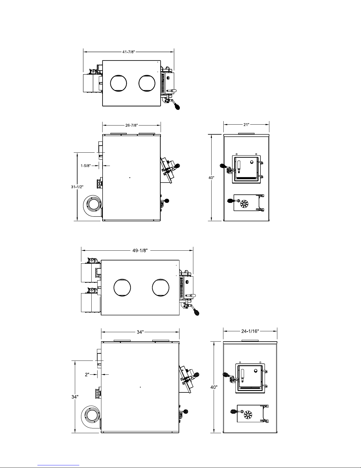
DIMENSIONS OF FURNACE
Figure 1
Model VG1500
Figure 2
Models VG2500
6
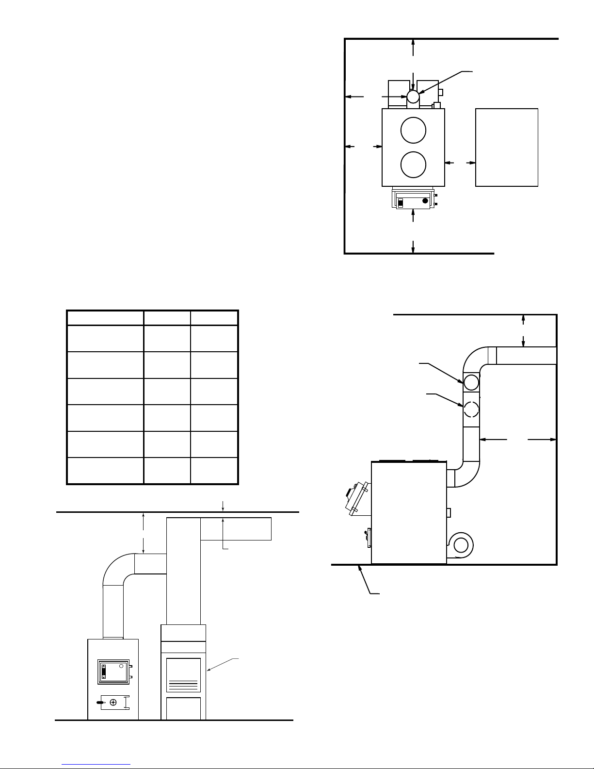
Locating the Furnace
18"
18"
6" SOLID DAMPER
6" BAROMETRIC
DRAFT REGULATOR
NON-COMBUSTIBLE FLOOR
12"
9"
48"
18"
CENTRAL
FURNACE
6" CHIMNEY
21"
1. The furnace should be located in the same
room as the central system and as close as
possible, but not closer than 9". There should
be no wall between the furnace and the warm
air outlet duct that is connected directly to the
warm air outlet plenum of the central furnace.
(See Fig. 4)
2. Place the furnace on a noncombustible oor.
3. Check gures 3 through 5. Be sure you have
the clearances shown below from the furnace
and the connector pipe to combustible surfaces. If you have a solid brick or stone wall
behind your furnace, you can place the furnace
as close as you wish to the wall. If the wall
is only faced with brick or stone, treat it as a
combustible wall.
Unit to Sidewall
Unit to Backwall
Front of Unit to
Combustible
Chimney Pipe
to Sidewall
Chimney Pipe
to Backwall
Plenum to
Combustibles6"(150mm)6"(150mm)
VG1500 VG2500
12"
(305mm)
30"
(760mm)
48"
(1.22m)
18"
(460mm)
18"
(460mm)
12"
(305mm)
30"
(760mm)
48"
(1.22m)
21"
(530mm)
18"
(460mm)
Figure 4
PLENUM
TO
CEILING
6" MIN.
2" MIN. AIR SPACE
REQUIRED BY CODE
Figure 5
CENTRAL
FURNACE
Figure 3
7

10'
2' MIN.
3' MIN.
6" CHIMNEY CONNECTOR
6" ELBOW
6" SOLID DAMPER
6" BAROMETRIC
DRAFT REGULATOR
REFER TO CHIMNEY
MANUFACTURER'S
INSTRUCTIONS AND
PARTS.
Chimney Connection
6" SOLID DAMPER
6" BAROMETRIC
DRAFT REGULATOR
THIMBLE
6" ELBOW
6" CHIMNEY
CONNECTOR
6" ELBOW
NON-COMBUSTIBLE WALL
MASONRY CHIMNEY
Before using an existing masonry chimney, clean
the chimney and inspect the ue liner to be sure
it is safe to use. Make repairs before attaching
the furnace. The connector pipe and ttings
you will need to connect directly to a masonry
chimney are shown.
The chimney connection should be as short as
possible.
If the connector pipe must go through a combustible wall before entering the masonry chimney,
consult a qualied mason or chimney dealer.
The installation must conform to local re codes,
and N.F.P.A. 211.
DO NOT CONNECT THIS FURNACE TO
A CHIMNEY FLUE SERVING ANOTHER
APPLIANCE.
The chimney used for a furnace must not be used
to ventilate the cellar or basement. If there is
a cleanout opening at the base of the chimney,
close it tightly.
Figure 6
LISTED FACTORY BUILT CHIMNEY
Carefully follow chimney manufacturer's instructions. Use only a Listed Residential Type or
Building Heating Appliance Chimney. If your
chimney starts at the ceiling (Fig. 7), you will
need enough 6" pipe to reach the ceiling.
The top of the chimney must be at least 3 feet
above the roof and be at least 2 feet higher than
any point of the roof within 10 feet (Fig. 7).
Figure 7
8
6" SOLID DAMPER
6" BAROMETRIC
DRAFT REGULATOR
NON COMBUSTIBLE
INSTALLATION PER
NFPA 211
MEASURE FLUE DRAFT HERE
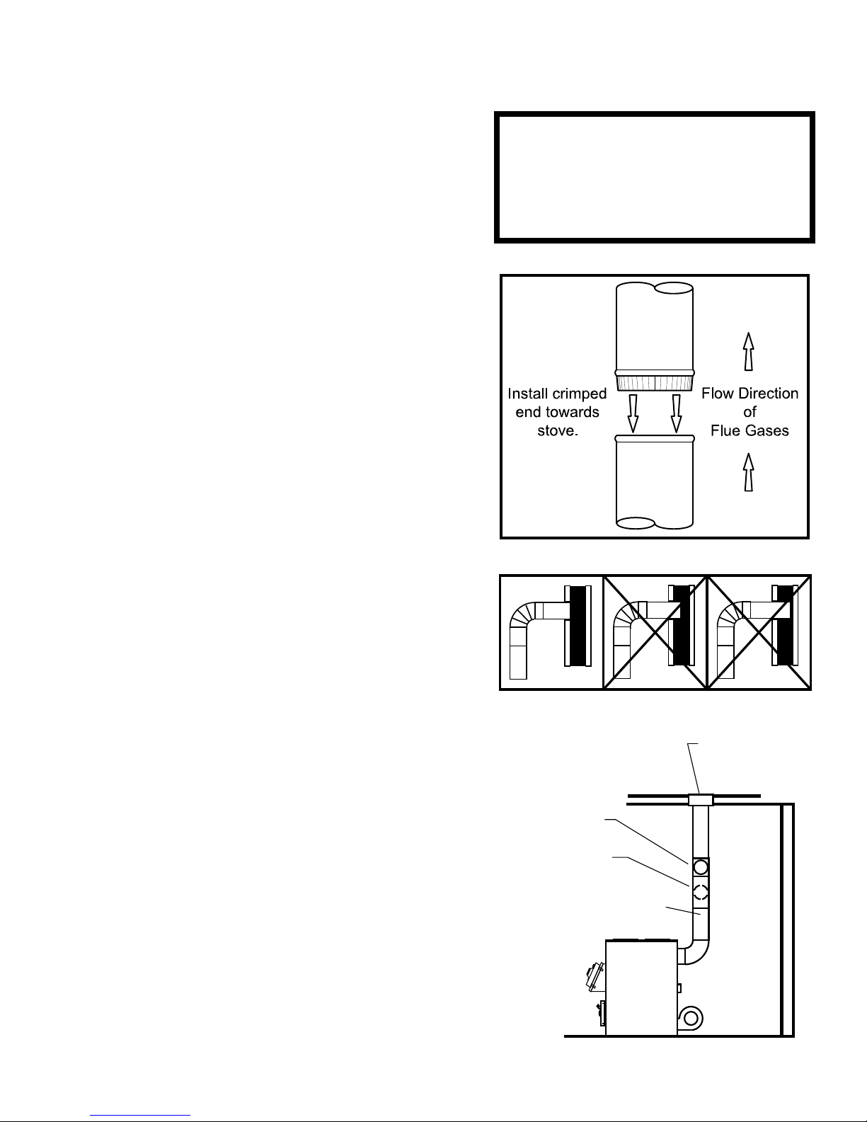
Rules for Connector Pipe Installation
1. The crimped end of the chimney connector ts inside
the furnace ue collar. Install additional chimney con-
nectors and elbow with the CRIMPED END TOWARD
THE FURNACE. This will allow any condensation
in the ue to run back into the furnace. Use 6" dia.
steel pipe and elbows for connection to chimney.
Never use less than 24 gauge and although blued
steel is satisfactory, high temp painted black is much
more desirable. (See Figure 8)
2. Slope any horizontal pipe upward toward the chimney
at least 1/4 inch for each foot of horizontal run.
3. You must have at least 18 inches of clearance be-
tween any horizontal piping and the ceiling.(See Fig.
5)
4. The chimney connector must not extend into the
chimney ue. (See Fig. 9)
5. Seal each chimney connector pipe joint with furnace
cement. Also seal the pipe at the chimney.
6. Use 3 sheet metal screws at each chimney pipe joint
to make the piping rigid.
7. The chimney connector may include a section for a
barometric draft regulator between the furnace and
the chimney (Fig. 6, 7, & 10). The barometric draft
regulator must be installed in the same room (same
pressure zone) as the furnace.
A ue pipe shall not pass through an attic, roof
space, closet or similar concealed space, a oor
or ceiling of combustible construction. Where
passage through a wall or partition is desired,
installation must conform with UL standards.
Figure 8
NOTE:
8. Install the barometric draft regulator strictly in ac-
cordance with the instructions that are provided with
the barometric draft regulator.
9. A solid damper must be used in the chimney connect-
ing pipes between the ue collar and the chimney.
When used in conjunction with a barometric draft
regulator, the solid damper must be placed between
the barometric and the chimney. (See Fig. 6, 7, & 10)
Adjusting the Barometric Draft Regulator
1. Drill a hole in the chimney connector within 18" of
the ue collar below the barometric draft regulator
just large enough for the tube of the manometer.
2. Build a re after all chimney connections have been
made.
3. Use a manometer to measure the draft in the ue.
4. Adjust the Barometric Draft Regulator to obtain a
draft of 0.05 - 0.06" W.C. under stable re conditions.
RIGHT WRONG WRONG
Figure 9
Figure 10
9
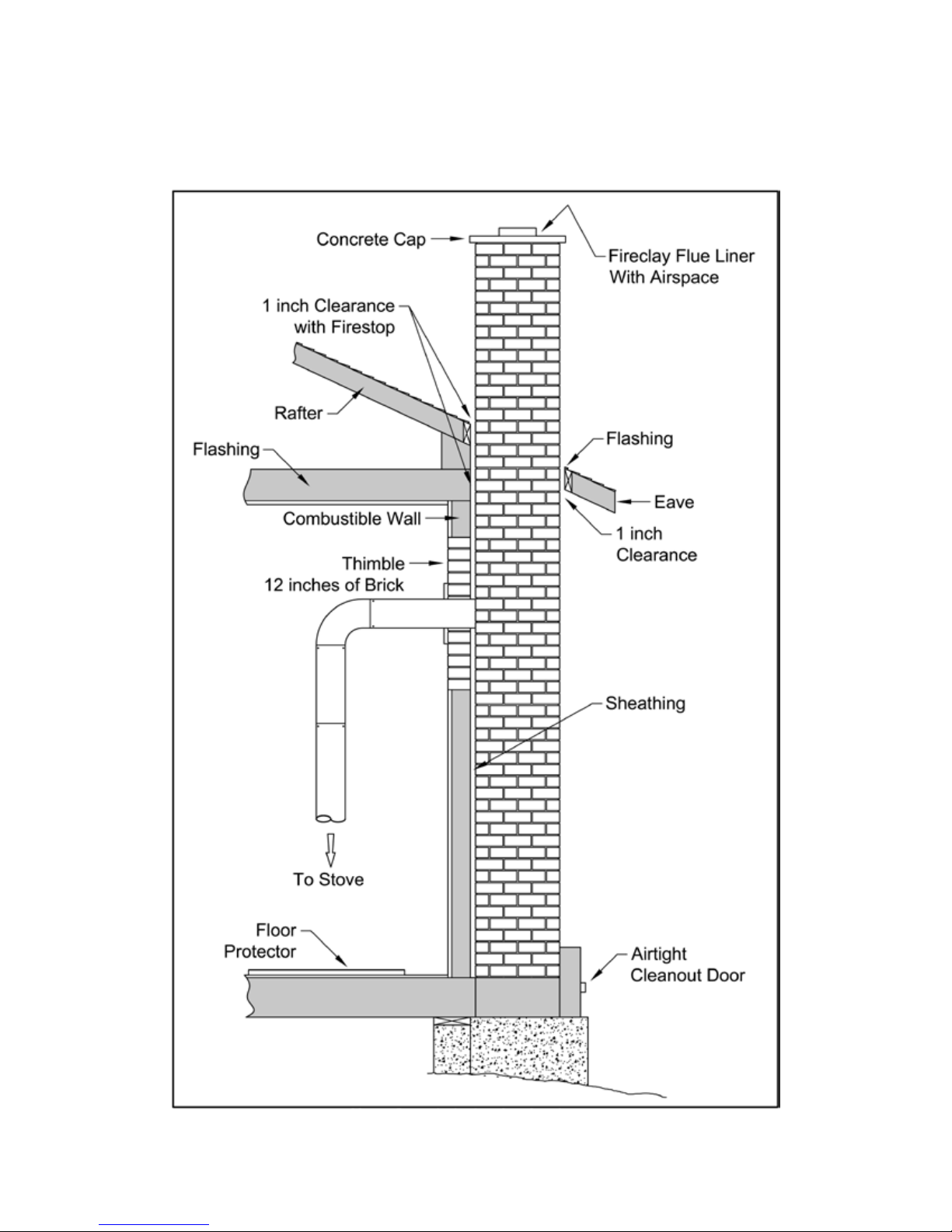
CONNECTION OF CHIMNEY CONNECTOR TO A MASONRY CHIMNEY THROUGH A COMBUSTIBLE WALL
Figure 8 shows how to connect the chimney connector of a heater to a masonry chimney through a combustible wall.
There are ve allowable ways that a chimney connector can be connected to a masonry chimney by passing through a
combustible wall. NFPA Standard 211 allows the following wall pass-through systems.
Figure 11
10
 Loading...