

Vogelzang International VG150 Owner's Manual
Owner’s Manual
MODELS: VG150
CAUTION: Please read this entire manual before
you install or use your new room heater. Failure to
follow instructions may result in property damage,
bodily injury, or even death. Improper Installation
Could Void Your Warranty!
SAFETY NOTICE: If this heater is not properly
installed, a house re may result. For your safety,
follow the installation instructions. Never use
make-shift compromises during the installation
of this heater. Contact local building or re
ofcials about permits, restrictions and installation
requirements in your area.
Save these instructions
This manual will help you to obtain efcient,
dependable service from the heater, and enable
you to order repair parts correctly. Keep in a safe
place for future reference.
Certied to comply with 2015 particulate emission standards for single burn rate heaters. Not approved for
sale after May 15, 2020. This single burn rate wood heater is not approved for use with a ue damper.
227 Industrial Park Road, South Pittsburg, TN 37380
CONFORMS TO
UL 1482-11 (R2015)
U.S. ENVIRONMENTAL PROTECTION AGENCY
SAFETY TESTED TO UL 1482
WASHINGTON STATE APPROVED
TESTED &
LISTED BY
OMNI-TEST LABORATORIES, INC.
REPORT NO.: 0215WS048E
0215WS048S
PORTLAND
OREGON, USA
U.S. Stove Company
1-800-750-2723 www.usstove.com 852466-1404F
CONGRATULATIONS!
You’ve purchased a heater from North America’s oldest manufacturer of wood burning products.
By heating with wood you’re helping to CONSERVE ENERGY!
Wood is our only Renewable Energy Resource. Please do your part to preserve our wood supply. Plant at
least one tree each year. Future generations will thank you.
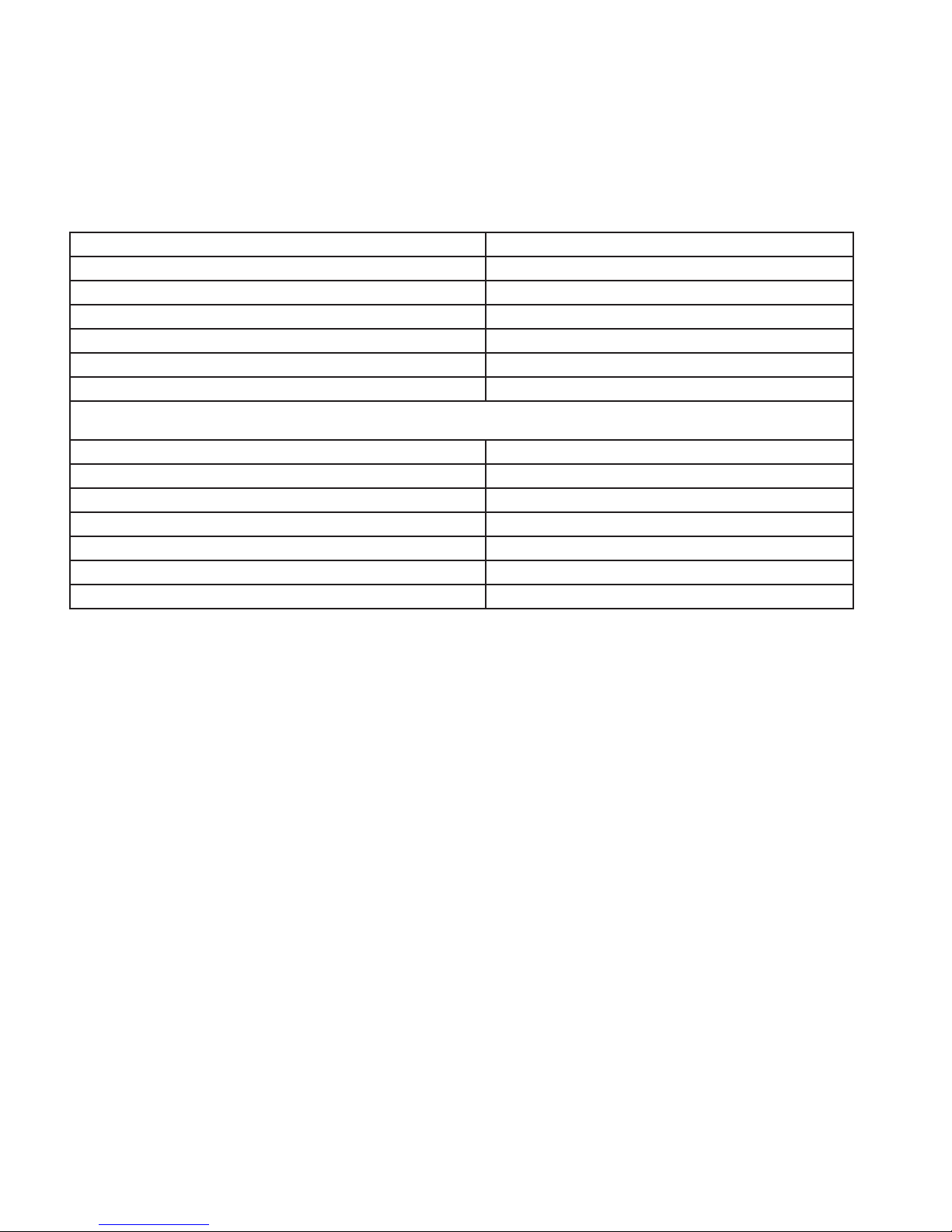
The instructions pertaining to the installation of your wood stove comply with UL-1482 standards.
Combustible: Wood
Colors: Metallic Black
Flue Pipe Diameter: 6” (135mm)
Flue Pipe Type: (Standard Single Wall or Double Wall): Single Wall Black or Blue Steel 2100 °F (650 °C)
Minimum Chimney Height: 12’ (3.7m)
Maximum Log Length: 17” (432mm)
Electrical: 120V, 60Hz, 31W
Dimensions
Overall ( Depth x Width x Height ): 26” X 17.5” X 25.5” (660mm x 445mm x 648mm)
Overall ( Depth x Width x Height ) with blower: 31” X 17.5” X 25.5” (787mm x 445mm x 648mm)
Combustion Chamber: Width x Depth: 13.6” X 17” (345mm x 432mm)
Volume: Cubic Feet: 1.6 ft²
Door Opening: 8” x 11.6” (203mm x 295mm)
Pyroceramic Glass Door : (Viewing) Width x Height: 3” x 4”(76mm x 102mm)
Weight (lbs): 235 lb
This manual describes the installation and operation of the United States Stove Company Model VG150 wood
heater. This heater meets the 2015 U.S. Environmental Protection Agency's crib wood emission limits for wood
heaters sold after May 15, 2015. Under specic EPA test conditions burning Douglas Fir dimensional lumber this
heater has been shown to deliver heat at a rate of 37,018 Btu/hr. This heater achieved a particulate emissions
rate of 2.96 g/hr when tested to method ASTM E2780-10 single Burn Rate Appendix (*and an efciency of
73.45 %.)
This wood heater has a manufacturer-set minimum low burn rate that must not be altered. It is against
federal regulations to alter this setting or otherwise operate this wood heater in a manner inconsistent with
operating instructions in this manual.
The operation of this wood heater in a manner inconsistent with the owner’s manual will void you warranty
and is also against federal regulations.
This wood heater needs periodic inspection and repair for proper operation. It is against federal regulations
to operate this wood heater in a manner inconsistent with operating instructions in this manual.
2
Safety Rules
SAFETY NOTICE: If this heater is not properly installed, a house re may result. For your safety, follow the
installation directions. Contact local building or re ofcials about restrictions and installation inspection
requirements in your area.
READ THESE RULES AND THE INSTRUCTIONS CAREFULLY
1. Check with local codes. The installation must
comply with their rulings. Observe closely the
clearances to combustibles.
2. Do not install this heater in a mobile home or
trailer.
3. Always connect this heater to a chimney and
vent to the outside. Never vent to another room
or inside a building. DO NOT CONNECT THIS
UNIT TO A CHIMNEY FLUE SERVING ANOTHER
APPLIANCE.
4. Do not connect a wood burning heater to a
Type B gas vent. This is not safe and is prohibited
by the National Fire Protection Association
Code. This heater requires approved masonry
or UL, ULC Listed Residential Type and Building
Heating Appliance Chimney. Use a 6" diameter
chimney, or larger, that is high enough to give
a good draft.
5. Be sure that your chimney is safely constructed
and in good repair. Have the chimney
inspected by the Fire Department or a qualied
inspector. Your insurance company may be
able to recommend a qualied inspector.
6. Inspect chimney connector and chimney
twice monthly during the heating season for
any deposit of creosote or soot which must be
removed (see Chimney Maintenance).
7. Provide air for combustion from outside the
house into the room where the heater is
located. If the intake is not in the same room,
air must have free access in to the room.
8. To prevent injury, do not allow anyone to use
this heater who is unfamiliar with the correct
operation of the heater.
9. For further information on using your heater
safely, obtain a copy of the National Fire
Protection Association (NFPA) publication "Using
Coal and Wood Stoves Safely" NFPA No. HS-10-
1978. The address of the NFPA is Batterymarch
Park, MA 02269.
• For more information on a Canadian
Installation, obtain a copy of CAN/CSA - B365
- M91 Installation Code for Solid-Fuel-Burning
Appliances and Equipment.
10. Disposal of Ashes - Ashes should be placed in
a metal container with a tight tting lid. The
closed container of ashes should be placed on
a noncombustible oor or on the found, well
away from all combustible materials, pending
nal disposal. If the ashes are disposed of by
burial in soil or otherwise locally dispersed, they
should be retained in the closed container until
all cinders have thoroughly cooled.
11. CAUTION - The special paints used on your
heater may give off some smoke while they are
curing during the rst few res. Build small res
at rst. Children and people/animals with lung
problems should take caution during the curing
process.
12. CARING FOR PAINTED PARTS - This heater has
a painted jacket which is durable but it will
not stand rough handling or abuse. When
installing your heater, use care in handling.
Clean with soap and warm water when heater
is not hot. DO NOT use any acids or scouring
soap, as these wear and dull the nish. PAINT
DISCOLORATION WILL OCCUR IF THE HEATER IS
OVERFIRED. FOLLOW OPERATING INSTRUCTIONS
CAREFULLY.
13. All persons, especially children, should be alerted
to hazards from high surface temperatures and
kept away while in operation. Small children
should not be left unsupervised when in the
room with the heater.
14. Keep the area adjacent to the heater free from
all combustible materials, gasoline, and other
ammable vapors.
15. This heater should not be used as a primary
source of heat.
CAUTION: Do not touch the heater until it has cooled.
NOTE: For your safety, we recommend installing smoke detectors in your home if not already installed.
3
TOOLS AND MATERIALS NEEDED FOR INSTALLATION
You will need a drill with a 1/8” bit to install sheet metal screws into connector pipe. A 5/16” socket/wrench or
screw driver to install the blower assembly described below. A 1/2” socket/wrench to install ue collar. A noncombustible oor protector as specied in this manual. All chimney and chimney connector components
required for your particular chimney installation.
4
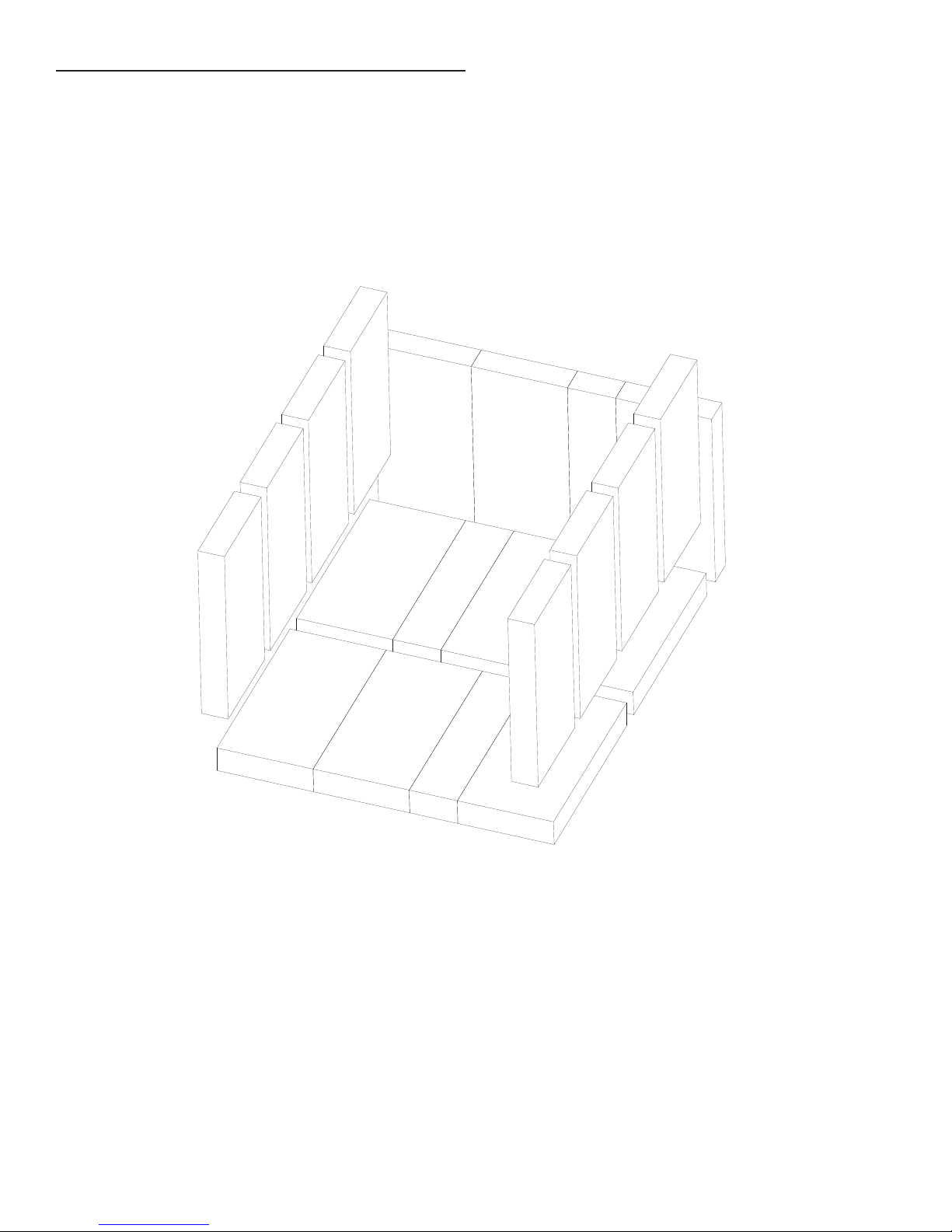
Brick Conguration
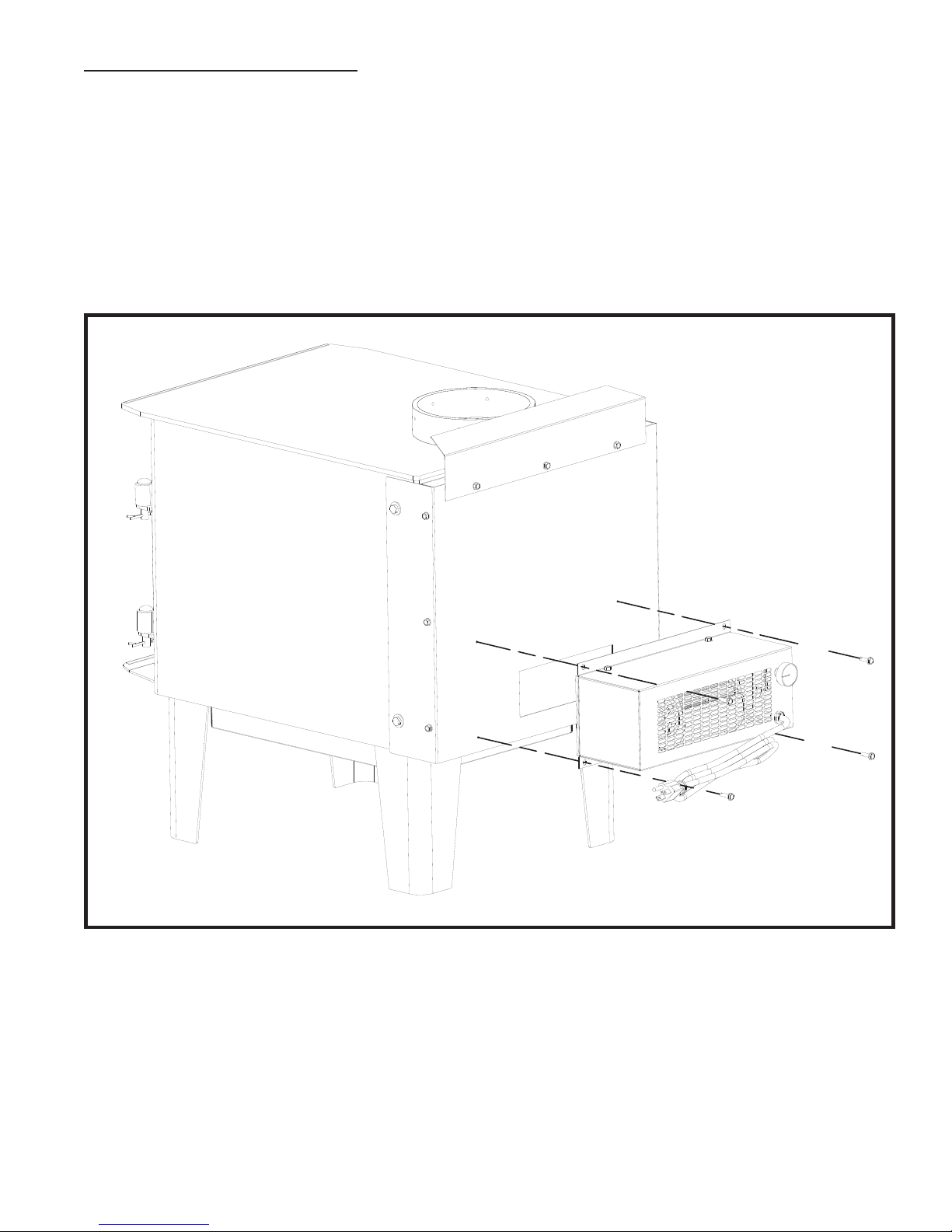
BLOWER ASSEMBLY INSTRUCTIONS
THE BLOWER ASSEMBLY MUST BE DISCONNECTED FROM THE SOURCE OF ELECTRICAL SUPPLY BEFORE
ATTEMPTING THE INSTALLATION.
Fix the assembly to the back of the stove with the four screws provided. The blower assembly is intended
for use only with a stove that is marked to indicate such use. Do not route the supply cord near or across hot
surfaces!
5
INSTALLATION
SAFETY NOTICE
• If this stove is not properly installed, a house re may result. To reduce the risk of re, follow the
installation instructions.
• Consult your municipal building department or re ofcials about permits, restrictions and installations
requirements in your area.
• Use smoke detectors in the room where your stove is installed.
• Keep furniture and drapes well away from the stove.
• Never use gasoline, gasoline-type lantern fuel, kerosene, charcoal lighter uid, or similar liquids to start
or “freshen up” a re in this heater. Keep all such liquids well away from the heater while it is in use.
• In the event of a chimney re, push the air control full closed to deprive the re of oxygen. Call the re
department.
• Do not connect to any air distribution duct or system.
• A source of fresh air into the room or space heated shall be provided when required.
POSITIONING THE STOVE
It is very important to position the wood stove as close as possible to the chimney, and in an area that will
favor the most efcient heat distribution possible throughout the house. The stove must therefore be installed
in the room where the most time is spent, and in the most spacious room possible. Recall that wood stoves
produce radiating heat, the heat we feel when we are close to a wood stove. A wood stove also functions
by convection, that is through the displacement of hot air accelerated upwards and its replacement with
cooler air. If necessary, the hot air distribution from the stove may be facilitated by the installation of a blower.
The wood stove must not be hooked up to a hot air distribution system since an excessive accumulation of
heat may occur.
A wood stove must never be installed in a hallway or near a staircase, since it may block the way in case of
re or fail to respect required clearances.
6
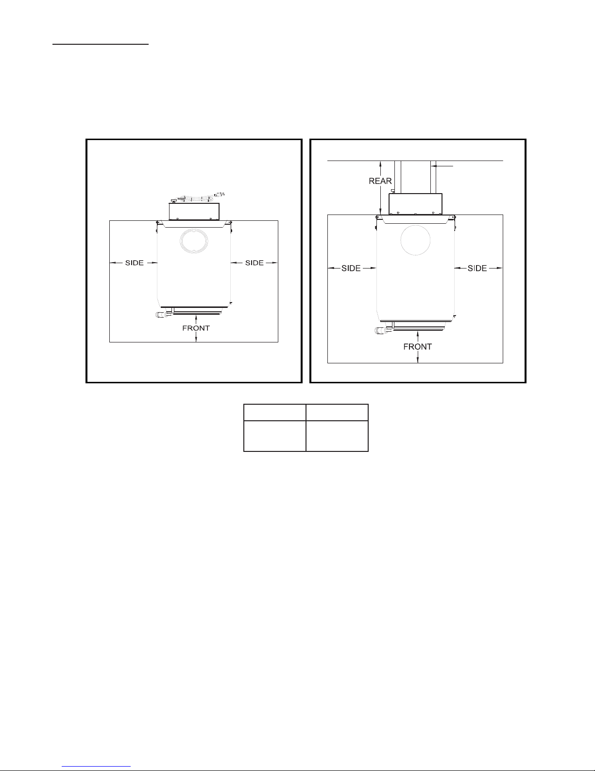
When ue pipe
exits the back your
oor protection
must extend 2”
(51mm) on both
sides of the ue.
FLOOR PROTECTOR
Manufactured oor protector conforms to UL 1618, that provides at minimum type 1 ember protection. The
oor protector should be under the stove, 16” inches beyond the front and 8” beyond each side of the fuel
loading and ash removal opening. If there is a horizontal section of chimney connector, the oor protector
should go under it and two inches beyond each side
The oor protector should exceed the stove as follows:
Front Sides
16”
(406mm)8”(203mm)
7
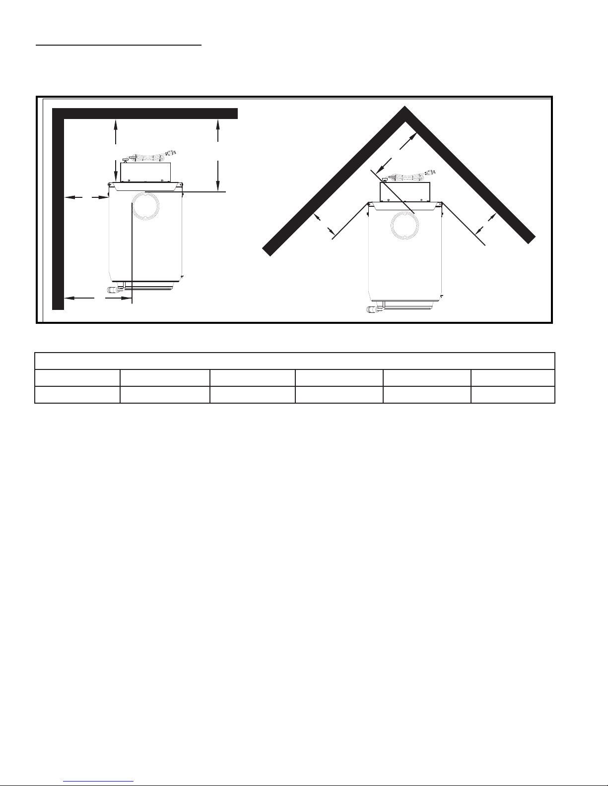
CLEARANCES TO COMBUSTIBLES
A
C
E
F
E
B
D
It is of utmost importance that the clearances to combustible materials be strictly adhered to during
installation of the stove. Refer to the tables below :
Clearance To Combustibles
A B C D E F
14” (356mm) 28” (711mm) 16” (406mm) 33” (838mm) 18” (457mm) 23” (585mm)
• Floor to ceiling height must be at least 8’ (2.4m) in all cases.
• Do not place any combustible material within 4’ (1.2m) of the front of the unit.
• The clearance between the ue pipe and a wall are valid only for vertical walls and for vertical ue pipe.
• The chimney connector must not pass through an attic or roof space, closet or similar concealed space,
a oor, or a ceiling.
• A ue pipe crossing a combustible wall must have a minimum clearance of 18” (457.2mm).
• To reduce ue clearances from combustible materials, contact your local safety department.
8
 Loading...