

Vogelzang International TR008 Durango Owner's Manual
THE DURANGO
™
HIGH-EFFICIENCY WOODSTOVE
EPA Certified (3.6 grams/hr)
Model TR008 Owners Manual
(save this manual for future reference)
Certified to comply with 2015 particulate emissions standards.
READ ALL INSTRUCTIONS CAREFULLY
BEFORE INSTALLING OR OPERATING
THIS STOVE. FAILURE TO FOLLOW INSTRUC-
TIONS MAY RESULT IN PROPERTY DAMAGE,
BODILY INJURY, OR EVEN DEATH.
REFER TO MARKINGS ON STOVE LABELS FOR
ADDITIONAL INFORMATION.
SAFETY NOTICE: IF THIS STOVE IS NOT PROPERLY INSTALLED, A HOUSE/BUILDING FIRE MAY
RESULT. FOR YOUR SAFETY, CONTACT LOCAL OR MUNICIPAL BUILDING OR FIRE OFFICIALS
ABOUT PERMITS, RESTRICTIONS, AND INSTALLATION REQUIREMENTS FOR YOUR AREA.
This stove meets test standards:
U.S. Environmental Protection Agency
US: UL 1482-2011
NOTE: IT IS RECOMMENDED INSTALLATION
BE COMPLETED BY A QUALIFIED HEATING
EQUIPMENT INSTALLER!
DO NOT INSTALL IN A MOBILE HOME.
U.S. Stove Company
Vogelzang
227 Industrial Park Road
,QGXVWULDO3DUN5RDG
South Pittsburg, Tennessee
6RXWK3LWWVEXUJ7HQQHVVHH
37380
www.vogelzang.com
3KRQH
www.usstove.com
Phone: 800-750-2723
Report No. 180-S-04-2
852142C -1902E

This manual describes the installation and operation of the Vogelzang, TR008 wood heater. This heater meets the
2015 U.S. Environmental Protection Agency's crib wood emission limits for wood heaters sold after May 15, 2015. Under specific test conditions this heater has been shown to deliver heat at rates ranging from 10,013 to 36,089 Btu/hr.
Note: The BTU ratings mentioned above are based on the EPA test protocol burning dimensional Douglas Fir lumber.
Our advertised BTU’s are based on the first hour of operation at high burn rate burning cordwood.
SAFETY INSTRUCTIONS-READ ALL INSTRUCTIONS CAREFULLY
1. The installation of this stove must comply with your local building code rulings. Please observe the clearances to
combustibles (see fi gures 5–7). Do not place fuel, furniture or any other objects within the clearance area.
2. Verify that the stove is properly assembled and installed before fi ring the stove for the fi rst time. After reading these
instructions, if you have any doubt about your ability to complete your installation properly, you must obtain the
services of a professional licensed installer familiar with all aspects of safe and correct installation. DO NOT use
temporary or makeshift compromises during installation. There must be NO DEVIATION
3. OR ALTERATION OF ANY KIND from the very specifi c instructions spelled out in this instruction manual as it
pertains to the installation of this woodstove. NO EXCEPTIONS!
4. DO NOT store wood, kindling, fl ammable liquids or other combustible materials in the vicinity of the appliance.
Refer to certifi cation label on back of unit and reference fi gures 5–7 in this manual.
5. DO NOT INSTALL THIS STOVE IN A MOBILE HOME, MANUFACTURED HOME, TRAILER OR TENT NO
EXCEPTIONS! (HUD Federal Standard: 24 CFR Ch.XX).
6. DO NOT ELEVATE THIS STOVE BY ANY MEANS. (i.e. bricks under legs, cement blocks) Stove legs must set
directly upon the solid-surface non-combustible fl oor as specifi ed in this stove instruction manual.
7. DO NOT MODIFY THIS STOVE IN ANY WAY! Stove must be installed with legs and heat shield provided, attached as
shown in the instructions. DO NOT OPERATE WITHOUT BOTTOM HEAT SHIELD IN PLACE – NO EXCEPTIONS.
Assemble only with original parts as supplied and shown in this manual. DO NOT OPERATE A STOVE THAT IS
MISSING ANY PARTS! If any parts are missing or defective, please notify the dealer or manufacturer immediately.
Replace missing, broken or worn parts with factory original or equivalent parts only.
8. CAUTION: DO NOT ALTER COMBUSTION AIR CONTROL RANGE TO INCREASE FIRING OR FOR ANY
REASON. Altering or tampering with air control beyond normal capacity will create unsafe and hazardous conditions.
9. Always connect this stove to a chimney and vent to the outside. Never vent to a room or inside a building. DO
NOT CONNECT THIS UNIT TO A CHIMNEY FLUE SERVING ANOTHER APPLIANCE.
10. DO NOT CONNECT A WOOD BURNING STOVE TO AN ALUMINUM TYPE B GAS VENT. This is not safe. Use
code-approved masonry chimney with fl ue liner or an Underwriters Laboratories Listed UL 103 HT (US)/ULC-S629
(CDN) Residential Type and Building Heating Appliance Chimney system. Use a 6˝/152mm diameter chimney, that
is high enough to give a good draft. (See specifi cs in Chimney Connections instructions).
11. Be sure that your chimney is safely constructed and in good repair. Have the chimney inspected by the fi re
department or a qualifi ed inspector. Your insurance company should be able to recommend a qualifi ed inspector.
Chimney connector pipe must be in good condition. Replace if necessary before using stove.
12. Creosote or soot may build up in the chimney connector and chimney and cause a house/building fi re. Inspect the
chimney connector and chimney twice monthly during the heating season and clean if necessary. (see Service Hints).
13. In the event of a chimney fi re, turn the air controls to closed positions, leave the building and CALL THE FIRE
DEPARTMENT IMMEDIATELY! Have a clearly understood plan on how to handle a chimney fi re by contacting
your local fi re authority for information on proper procedures in the event of a chimney fi re. After the fi re is out, the
chimney must be cleaned and inspected for any stress or cracks before starting another fi re. Check the condition
of any combustibles surrounding the chimney.
14. Ashes should not be allowed to accumulate above the top of the lower primary air orifi ce (LPAO, air vent at front
of fi rebox, just inside of door).
15. DISPOSAL OF ASHES Ashes should be placed in a steel container with a tight fi tting lid and moved outdoors
immediately. The closed container of ashes should be placed on a noncombustible fl oor or on the ground, well away
from all combustible materials, pending fi nal disposal. If the ashes are disposed of by burial in soil or otherwise
locally dispersed, they should be retained in the closed container until all cinders have completely cooled. Other
waste shall not be placed in this container.
16. To prevent injury, do not allow anyone to use this stove who is unfamiliar with the correct operation of the stove.
17. Do not operate stove while under the infl uence of drugs or alcohol.
18. DO NOT ELEVATE THE FIRE. Build fi re directly on the bottom of the fi rebox. This stove has not been tested with
the use of grates, andirons or other means of elevating the fi re and must not be used.
NOTE: A LICENSED PROFESSIONAL HEATING AND COOLING CONTRACTOR SHOULD BE CONSULTED
IF YOU HAVE QUESTIONS REGARDING THE INSTALLATION OF THIS SOLID FUEL BURNING APPLIANCE.
2

SAFETY INSTRUCTIONS
18. The special paints used on your stove may give off some smoke and an odor while they are curing during the fi rst
12 to 15 fi res. Additional smoke and odor may be emitted from the light oils used in construction of the fi re box.
This should disappear after a short period of time and not occur again. Persons with lung conditions or owners of
susceptible domestic pets (such as birds) should take prudent precautions. Open windows and doors as needed
to clear smoke and/or odor. Paint discoloration will occur if the stove is over fi red.
19. This stove has a painted surface which is durable but it will not stand rough handling or abuse. When installing
your stove, use care in handling.
20. CLEAN STOVE FREQUENTLY as soot, creosote and ash may accumulate. Clean exterior with soap and warm
water when stove is not hot. Do not use any acids or scouring soap, as these solvents wear and dull the fi nish.
21. ALERT ALL PERSONS TO THE HAZARDS OF HIGH SURFACE TEMPERATURES while stove is in operation
– especially young children. Keep away from a hot stove to avoid burns or clothing ignition.
22. NEVER LEAVE SMALL CHILDREN UNSUPERVISED WHEN THEY ARE IN THE SAME ROOM AS THE STOVE.
If small children will be in the same room as the stove during operation, provide a sturdy barrier to keep them at
a safe distance from the stove.
23. Keep stove area clear and free from all combustible materials, gasoline, engine oil, naphtha and other fl ammable
vapors and liquids.
24. WHILE TENDING THE FIRE ALWAYS WEAR PROTECTIVE CLOTHING, fi re retardant hearth gloves and eye
protection, to prevent burns.
25. Never operate this stove with the door open except when re-fueling. Such actions can result in very dangerous
operating conditions.
26. DO NOT OVER FIRE THE STOVE. Over fi ring will occur if combustion air is uncontrolled as when feed door is left
open during operation. Such actions can result in very dangerous operating conditions. While in operation, keep
the feed door closed and secured at all times except while tending the fi re
27. When adding fuel be careful not to smother the fi re. Do not build fi res against glass and do not load fuel to a height
or in such a manner that it creates a hazard when opening the door.
28. NEVER LEAVE THE STOVE UNATTENDED with door open. Always close the door after ignition.
29. DO NOT CONNECT TO OR USE IN CONJUNCTION WITH ANY AIR DISTRIBUTION DUCT WORK UNLESS
SPECIFICALLY APPROVED FOR SUCH INSTALLATIONS.
30. A WOOD-BURNING STOVE MUST NEVER BE INSTALLED IN A HALLWAY OR NEAR A STAIRCASE, as it
may block egress in the event of a fi re.
31. DO NOT INSTALL IN A SLEEPING ROOM. DO NOT INSTALL IN AN ALCOVE OR INSIDE A FIREPLACE.
32. Install at least one smoke detector on each fl oor of your home. Detectors should be located away from the heating
appliance to avoid false alarms. Detectors should be located close to sleeping areas. Follow the smoke detectors
manufacturer’s placement and installation instructions. Maintain smoke detector per manufacturer’s instructions.
33. CARBON MONOXIDE (CO) HAZARD. A buildup of CO fumes is toxic and can be fatal. Carbon Monoxide is a
colorless, odorless gas produced during combustion of wood, coal, oil, gas and by other fuel burning appliances. It
is important to have a proper draft and adequate replacement air ventilation so fumes are drawn out the chimney.
Installed as instructed this stove is designed to be as safe as possible yet it is recommended to install a CO
detector. Follow the manufacturer’s recommendations for proper installation and use. It is recommended to be
placed at table-top level (not near the ceiling) to avoid false alarms. Realize that devices other than a stove (i.e.
motor exhaust) can trigger CO alarms.
If alarm sounds:
• Recognize the symptoms of CO poisoning (headaches, nausea & drowsiness).
• Increase ventilation (open windows & doors).
• Make sure stove doors and/or lids are closed and secured.
• Check stove for smoking or puffi ng (open airfl ow controls).
• Check chimney & connector pipe for leaks, blockage or down-draft conditions.
• Check CO device for false alarm.
34. Keep power cords, electrical appliances and/or assemblies outside of the clearance area shown in this manual
for combustible materials.
35. Consult your municipal building department or fi re offi cials about restrictions, permits and installation requirements
for your area.
36. For further information on using your stove safely, obtain a copy of the National Fire Protection Association (NFPA)
publication, “Using Coal and Wood Stoves Safely” NFPA No. HS-10-1978. Write NFPA, Batterymarch Park, Quincy,
MA 02269.
3
ASSEMBLY INSTRUCTIONS
NOTICE: U.S. Stove grants no warranty, stated or implied, for the installation or maintenance of your wood
stove and assumes no responsibility of any incidental or consequential damages.
TOOLS AND MATERIALS REQUIRED FOR INSTALLATION
Tools:
• Pencil
• 6 foot Folding Rule or Tape Measure
• Tin Snips
• Drill: Hand or Electric
• 1/8” dia. Drill Bit (for sheet metal screws)
• Screwdrivers (blade and Phillips type)
• 14mm Nut Driver or Ratchet with 14mm Socket
• Safety Glasses
• Gloves
Materials:
(NOTE: The following items are NOT included with your stove) Flooring Protection: 33˝ x 48˝ as specifi ed (see page 4)
Chimney Connection Pipe: 6˝ black steel (24 ga. min.) straight stove pipe or elbow (as required) 1/2” Sheet Metal Screws
Chimney: Existing 6˝ Lined Masonry Chimney or 6˝ Inside Dia. Listed Type HT chimney. Furnace Cement (manufacturer
recommends Rutland Code 78 or equivalent)
STOVE IS HEAVY. MAKE SURE YOU
HAVE ADEQUATE HELP AND USE
PROPER LIFTING TECHNIQUES
WHENEVER MOVING STOVE.
CAUTION:
DO NOT
REMOVE!
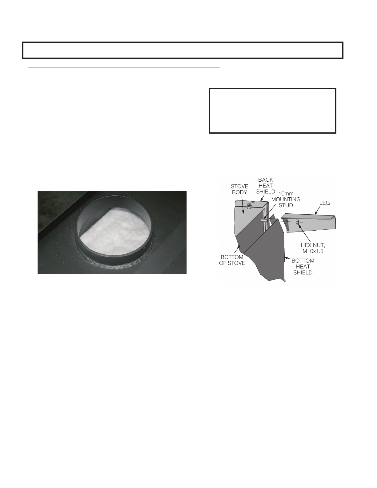
Figure 1 – DO NOT remove ceramic blanket from inside
stove pipe opening. This is NOT packing material but an
integral component of the stove combustion system.
NOTE: Reference numbers correlate to exploded view and parts list shown on pages 18 & 19.
1. Uncrate the stove and remove cardboard packing and protective poly bag. Remove bottom heat shield (#16) from
carton. (Save cardboard for further assembly.) NOTICE: DO NOT remove ceramic blanket material from inside
stove pipe opening (Fig. 1). This blanket provides an air seal on the side walls of the stove to direct combustion
gasses over the secondary combustion tubes before exiting via the chimney. DO NOT REMOVE the ceramic
blanket or your stove will not operate properly.
2. Remove parts from inside stove. Parts include: Blower Assembly (#F-6), Legs (#5) and Hardware Pack (#08-HP)
located inside fi rebox. NOTE: Stove body is HEAVY. Make sure you have adequate help to lift stove body and
use proper lifting techniques. Stove may be lightened during installation by removing fi re brick. Replace fi rebrick
before using. There are fi ve different sizes of brick. Note the location of each while removing or refer to fi gure 6
for proper location inside fi rebox.
3. Place fl attened carton on fl oor to protect stove fi nish and lay stove onto it’s side.
4. Remove the hex nuts (#28) from the leg mounting studs on the four corners of the bottom of the stove.
5. Position the bottom heat shield, fi gure 2, aligning the corner holes with the four leg mounting studs. The smaller
cutout must align with the air intake in
6. Align each leg with the mounting stud and slide into place. Replace the leg mounting hardware (hex nut, fi g. 2)
after installing the leg. After all four legs have been installed, tighten all mounting hardware.
7. Return the stove to the upright position.
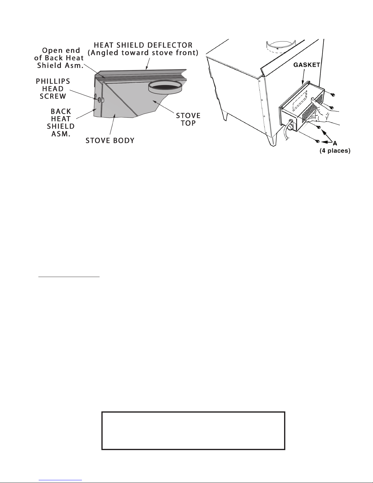
8. Attach the back heat shield assembly (#2) to the rear of the stove. The closed end is positioned to the bottom of
the stove with the open end up, fi g. 3. Secure the back heat shield with four Phillips head machine screws using
the threaded holes located in the rear side corners of the stove.
Fig. 2 – LEG ASSEMBLY
Bottom Heat Shield and Leg assembly
4
ASSEMBLY INSTRUCTIONS
Fig. 3 – Back Heat Shield and
Defl ector Assembly (top view)
1. Attach the heat shield defl ector (#17) to the top of the back heat shield assembly with three Phillips head machine
screws. The angled lip of the defl ector should face toward the front of the stove.
2. Attach blower assembly to rear of the back heat shield with four Phillips head machine screws from the hardware
pack. Make sure to position the ceramic gasket between the back heat shield and the blower assembly so it does
not block the fan opening.
3. After properly locating fl oor protector (fi g 5) to accommodate minimum stove clearances, place stove in position
on fl oor protector.
4. Route the power cord away from stove. Do not allow the power cord to touch any hot surfaces. Keep power cord
at least 12” from stove surfaces.
5. Check to make sure that the bottom fi re bricks (#13) and ceramic fi ber boards (parts #18 & #19) above the air tube
assembly (#6) have not shifted during shipping or assembly.
6. Once stove is positioned, plug power cord into a grounded 120v outlet.
Fig. 4 – Blower attaches
to rear heat defl ector
LOCATING STOVE
1. The stove must be placed on solid concrete, solid masonry, or when installed on a combustible fl oor, on a UL1618
Type 2 listed fl oor protector with minimum dimensions of 33˝ x 48˝, such as Hy-C or Imperial Model UL3648BK
or equivalent. Floor protector must be 1/2” minimum thickness (K value =0.84, R value = 0.59, see page 22 for
calculation formulas) non-combustible material or equivalent. The base must extend at least 16” beyond the front
of the access door, 8” to the sides of fuel opening. It must extend under and 2 inches beyond either side of the
stove pipe if it is elbowed towards a wall. (See fi gures 5 & 7 and consult local building codes and fi re protection
ordinances.)
2. The stove must have its own fl ue. DO NOT CONNECT THIS UNIT TO A CHIMNEY FLUE SERVING OTHER
APPLIANCES.
3. After observing the clearances to combustible materials (fi gures 5–7), locate your fl oor protector accordingly (fi gure
5) and carefully place the stove in your selected location. Install stove pipe, elbows, and thimble as required, utilizing
either a recently cleaned and inspected 6” masonry chimney or a 6” i.d. listed type HT chimney.
4. Use round 6˝/152mm dia., minimum 24 MSG black or 26 MSG blue steel stove pipe to connect the stove to the
chimney. DO NOT USE GALVANIZED PIPE AS A CONNECTOR. Secure pipe/elbow sections with a minimum of
three (3) equally spaced sheet metal screws at each joint and at the stove collar to make the pipe rigid. DO NOT
CONNECT THIS STOVE TO ANY AIR DISTRIBUTION OR DUCT SYSTEM.
5. Recheck clearances from the stove, connector stove pipe, and corner clearances using the illustrations in fi gures
5-7 and your local building codes or fi re protection ordinances.
(FIRE HAZARD) CARPETING AND OTHER COMBUSTIBLE
MATERIAL SHALL NOT COVER THE FLOOR PROTECTOR.
OF COMBUSTIBLE CLEARANCES, SEE FIG. 5 – 7..
5
CAUTION:
THESE MATERIALS MUST REMAIN OUTSIDE
LOCATING STOVE
TOP VIEW
NOTE: ANY WALL CONTAINING COMBUSTIBLE MATERIAL SUCH AS WOODEN STUDS OR DRYWALL AND
FACED WITH BRICK OR STONE MUST BE CONSIDERED A COMBUSTIBLE SURFACE.
6. DO NOT INSTALL THIS STOVE IN A MOBILE HOME, MANUFACTURED HOME, TRAILER OR TENT – NO
EXCEPTIONS! (HUD Federal Standard: 24 CFR Ch.XX)
7. The clearances provided are minimum dimensions determined by OMNI-Test Laboratories, Inc., the manufacturer’s
testing laboratory. Installation of this stove must comply with the latest edition of NFPA 211 for reduced clearances
and/or your local building code rulings. Use whichever minimum dimensions are LARGEST.
8. This stove meets U.S. Test Standard: UL 1482-2011.
9. Always locate stove to provide a source of fresh air into the room where the unit is installed. Failure to do so may
result in air starvation of other fuel burning appliances and the possible development of hazardous conditions
CAUTION:
FAILURE TO FOLLOW THESE MINIMUM CLEARANCE
REQUIRE - MENTS MAY RESULT IN AN UNSAFE
INSTALLATION AND COULD CAUSE A FIRE.
COMBUSTIBLE CONSTRUCTION PER NFPA 211
DASHED LINES SHOW HORIZONTAL CHIMNEY CONNECTOR
AND ADDITIONAL FLOOR PROTECTOR REQUIRED BENEATH
AND EXTENDING 2” BEYOND EACH SIDE
33"
4 8"
31"
FLOOR
16"min.
8"min.17"
22"
BA CKWALL
TR008
PROTECTOR
14"
min.
SIDEWALL
11"
min.
28.5
25.8"
min.
min.
min.
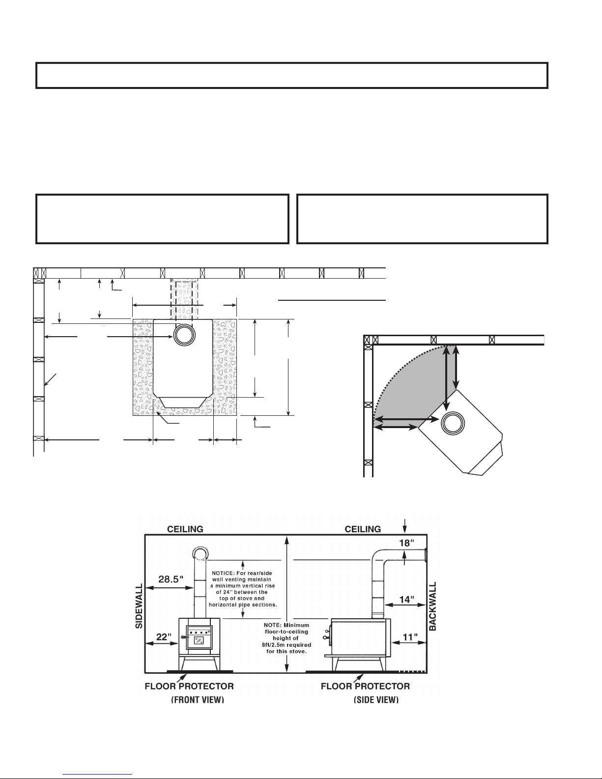
Fig. 5 – Top View Minimum Clearance Dimensions from
Combustible Surfaces
CAUTION:
KEEP FURNISHINGS AND OTHER COMBUSTIBLE
MATERIALS AWAY FORM THE STOVE AND OUTSIDE
MINIMUM CLEARANCES.
CORNER CLEARANCES
13"
19"
19"
13"
Fig. 6 – Minimum Corner Clearance
Dimension from Combustible Surfaces
6
Fig. 7 – Front & Side Views:
Minimum Clearance Dimensions
from Combustible Surfaces
LOCATING STOVE
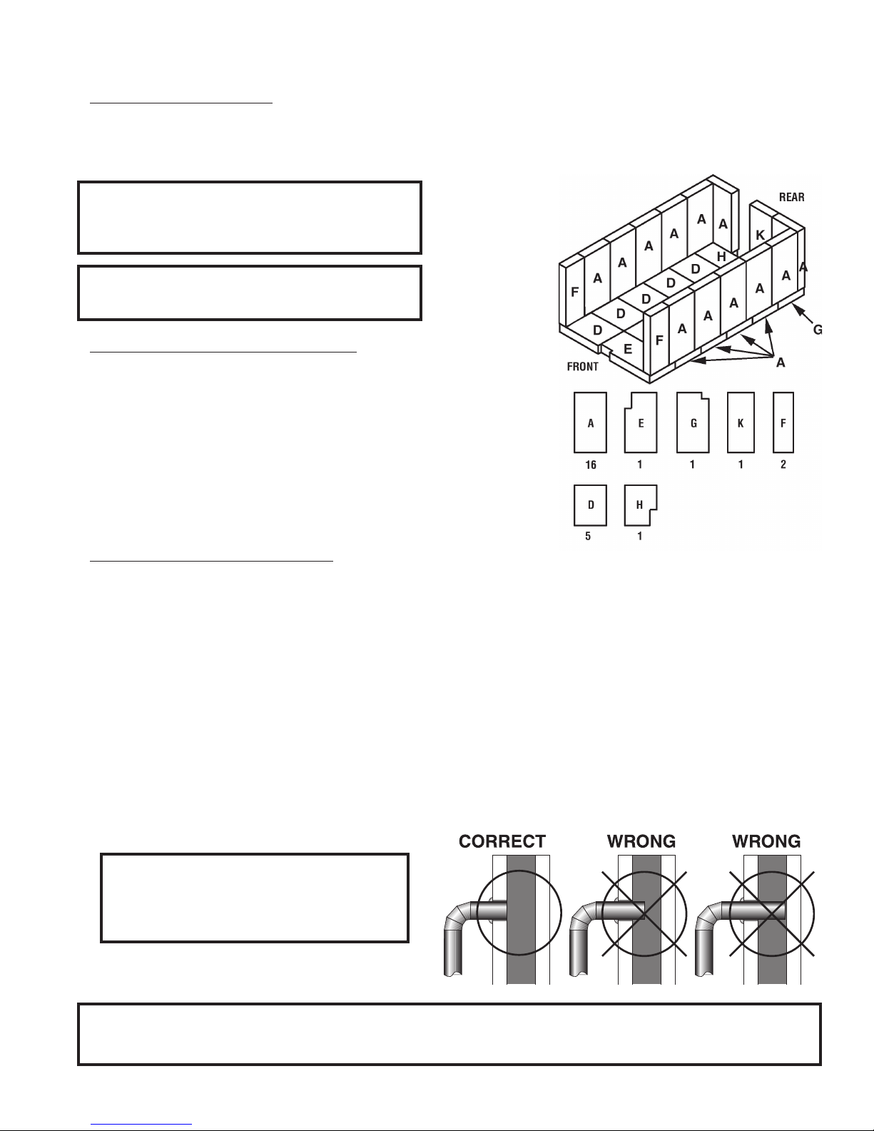
FIREBRICK ASSEMBLY
Firebrick protects the stove body, extends the life of your stove and radiates heat more evenly. Check to see that all
fi rebricks are in their correct positions and have not become misaligned during shipping or assembly. If removed for
ease of locating stove, fi rebrick must be replaced before fi ring. There are four different full-sized bricks (A, K, F, D) and
three (E, G, H) with notches. See diagram, fi g. 8, for proper positioning.
CAUTION:
REPLACE FIREBRICKS BEFORE FIRING
WOODSTOVE. POSITION FIREBRICKS SO
NO GAPS REMAIN BETWEEN BRICKS.
CAUTION:
NEVER OPERATE STOVE WITH MISSING
OR CRACKED FIRE BRICKS!
CONNECTOR PIPE INSTALLATION
Connector pipe is used to make the connection from the fi nal positioning
of your stove to a code-approved masonry chimney with fl ue liner or a
manufactured UL 103 HT listed chimney system. Connector pipe is NOT
included as part of the stove. Connector pipe must be 6” diameter minimum
of 24 MSG (minimum standard gauge) black or 26 MSG blue steel stove
pipe. Connector pipe is not rated to provide close contact to combustible
materials and must have proper clearance from combustible materials as
shown in the clearance diagrams on the previous pages. Connector pipe
should never be used in place of a chimney. If proper clearances are not
observed a house fi re could result.
Fig. 8 Firebrick
Installation
INSTALLATION INSTRUCTIONS
1. The tapered end of the connector stovepipe fi ts into the stove fl ue collar. Secure with three sheet metal screws.
Notice: For side or rear venting, you must have a minimum 24” vertical rise from top of stove to horizontal pipe
sections (see fi g. 7).
2. Horizontal pipe runs must slope upwards towards the chimney at least 1/4” per foot of horizontal run.
3. You must have at least 18 inches of clearance between any horizontal piping and the ceiling.
4. The pipe cannot extend into the chimney fl ue (fi g. 9).
5. Secure pipe/elbow sections with a minimum of three (3) equally spaced sheet metal screws at each joint and at
the stove collar to make the pipe rigid.
6. It is recommended that no more than two (2) 90 degree bends be used in the stovepipe installation. The use of
more than two 90 degree bends may decrease the amount of draw and possibly cause smoke spillage. Where
possible, use only corrugated (nonadjustable) elbows. These provide a better seal.
7. The connector pipe must not pass through an attic or roof space, closet, or any concealed space, or fl oor, ceiling,
wall or combustible construction. (See Chimney Connector Systems & Clearances, page 22). A UL 103 HT Listed
Chimney System must be used from the fi rst penetration of ceiling or wall to the chimney cap. Installation must
conform to the latest edition of NFPA 211.
WARNING:
DO NOT USE SINGLE WALL CONNECTOR
PIPE AS A CHIMNEY - A HOUSE FIRE
COULD RESULT.
NOTE: CONNECTOR PIPE IS NOT INCLUDED. TO PURCHASE, VISIT YOUR LOCAL HARDWARE, HOME
OR BUILDING CENTER. SEE “LOCATING STOVE” PAGE 6 FOR ADDITIONAL SPECIFICATIONS
7
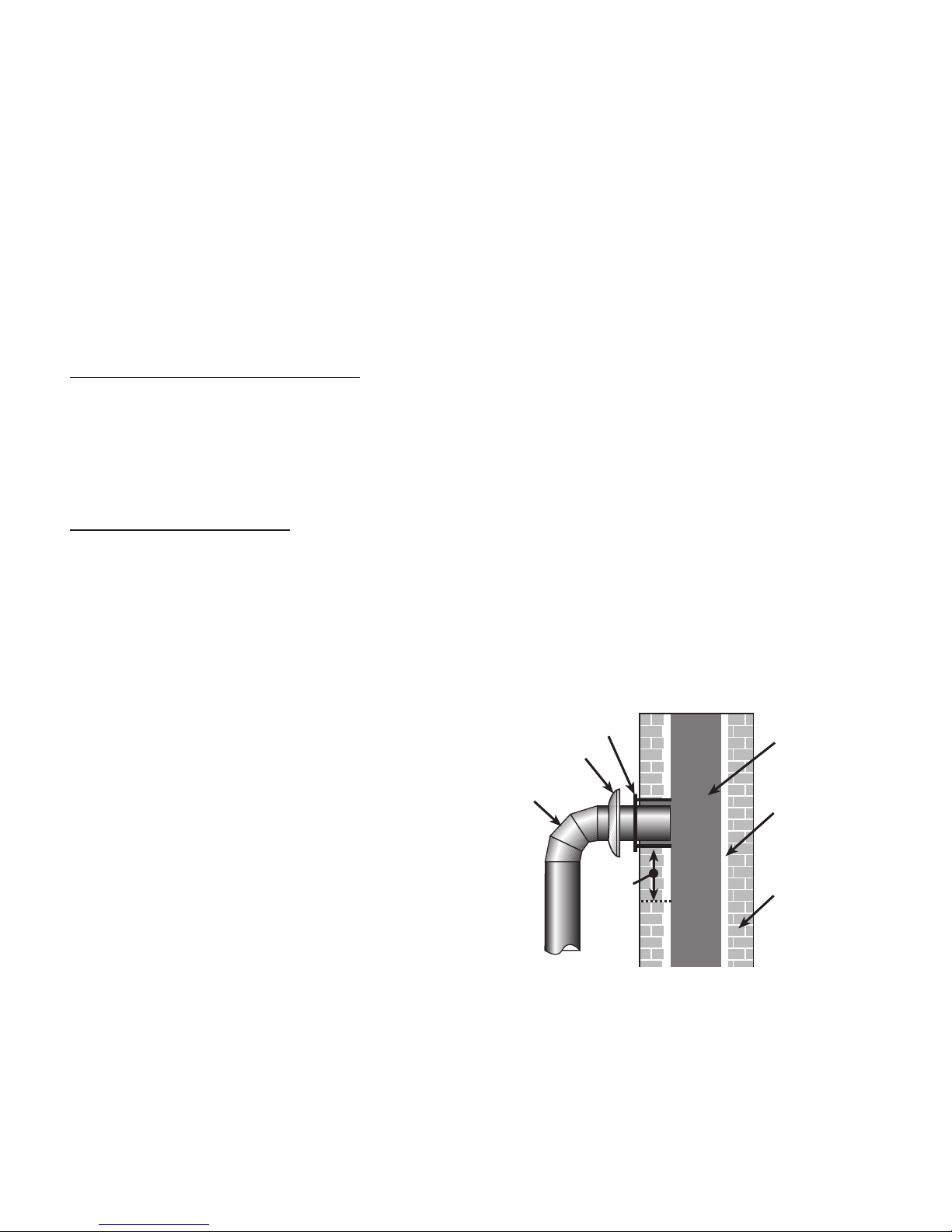
Fig.9 – Stovepipe/Flue Connections
CHIMNEY SIZING
Today’s solid fuel heating appliances are much more effi cient than those made in the past. Your heating appliance
has been designed to provide the most effi cient transfer of heat possible from the least amount of fuel. Controlled
combustion is the key to optimum heating performance. Controlled combustion requires a fl ow of fresh air into the
appliance, across the fuel and is fi nally exhausted up the chimney. Today’s high effi ciency stoves transfer more heat
into the living area and less up the chimney. Exhaust gases are typically at a lower temperature than traditional type
stoves. With lower exhaust temperatures, it is important that the chimney is correctly sized to the stove. If the chimney
diameter is too large, it will be diffi cult to raise the chimney fl ue temperature to provide for adequate draft. This may
result in a poor burn, smoke spillage, and rapid creosote creation. A 6” diameter chimney is best suited for this stove.
Your heating appliance must have a minimum of a 6” diameter (152mm) chimney. Maximum chimney diameter must
not exceed 10” (254mm) or have a cross sectional area greater than 85 sq. in. (550cm2.) Proper draft for this heating
appliance is minimum of 0.05 w.c. (water column measurement) and is required to prevent back puffi ng, smoke spillage
and prevent safety hazards. Take into account the chimney’s location to insure it is not too close to neighbors or in a
valley which may cause unhealthy or nuisance conditions.
IMPORTANCE OF PROPER DRAFT
Draft is the force which moves air from the appliance up through the chimney. The amount of draft in your chimney
depends on the length of the chimney, local geography, nearby obstructions and other factors. Too much draft may
cause excessive temperatures in the appliance and may damage. Inadequate draft may cause backpuffi ng into the
room and ‘plugging’ of the chimney.
“Inadequate draft will cause the appliance to leak smoke into the room through appliance and chimney connector joints.”
“An uncontrollable burn or excessive temperature indicates excessive draft.”
CHIMNEY CONNECTIONS
The stove must be connected to either a codeapproved masonry chimney with fl ue liner or manufactured metal
chimney system built and tested to the specifi cations listed on the previous pages. Chimneys perform two functions:
1. As a means of exhausting smoke and fl ue gases which are the result of fuel combustion.
2. The chimney (only) provides “draft” which allows oxygen to be continuously introduced into the appliance, so that
proper combustion is possible. This stove relies on natural draft to operate.
NOTICE: Always provide a source of fresh air into the room where the stove is located. Failure to do so
may result in air starvation of other fuel burning appliances and the possible development of hazardous
conditions, fi re or death.
A stove DOES NOT create draft. Draft is provided by the chimney. To achieve proper draft your chimney must meet
the four minimum height requirements detailed in
fi gures 11–13. If these minimum requirements
are not met your stove will not operate
properly. A minimum of 0.05 w.c. (measured in
water column) is required for proper drafting to
prevent back
puffing, smoke spillage, and to maximize
performance. (Gauges to measure draft are
readily available at stove stores and are
economical to rent or purchase.) Factors such
as wind, barometric pressure, trees, terrain
and chimney temperature can have an adverse
effect on the draft. The manufacturer cannot be
held responsible for external factors leading to
Fig. 10 - Masonry
less than optimal drafting. Should you have a
problem with inadequate draft, you should contact
a licensed heating and cooling contractor for
assistance in solving the problem. For a more
in-depth explanation see Chimney Draft on page 15.
THIMBLE
COLLAR
6˝ ROUND
24 ga. BLACK
CONNECTOR
STOVEPIPE
8˝ MIN.
LINER
BELOW
ENTRY
HOLE
Chimney
Connection
CHIMNEY
FLUE
5/8" TILE
CHIMNEY
LINER
MASONRY
CHIMNEY
8
 Loading...