

Vogelzang International TR007 Owner's Manual
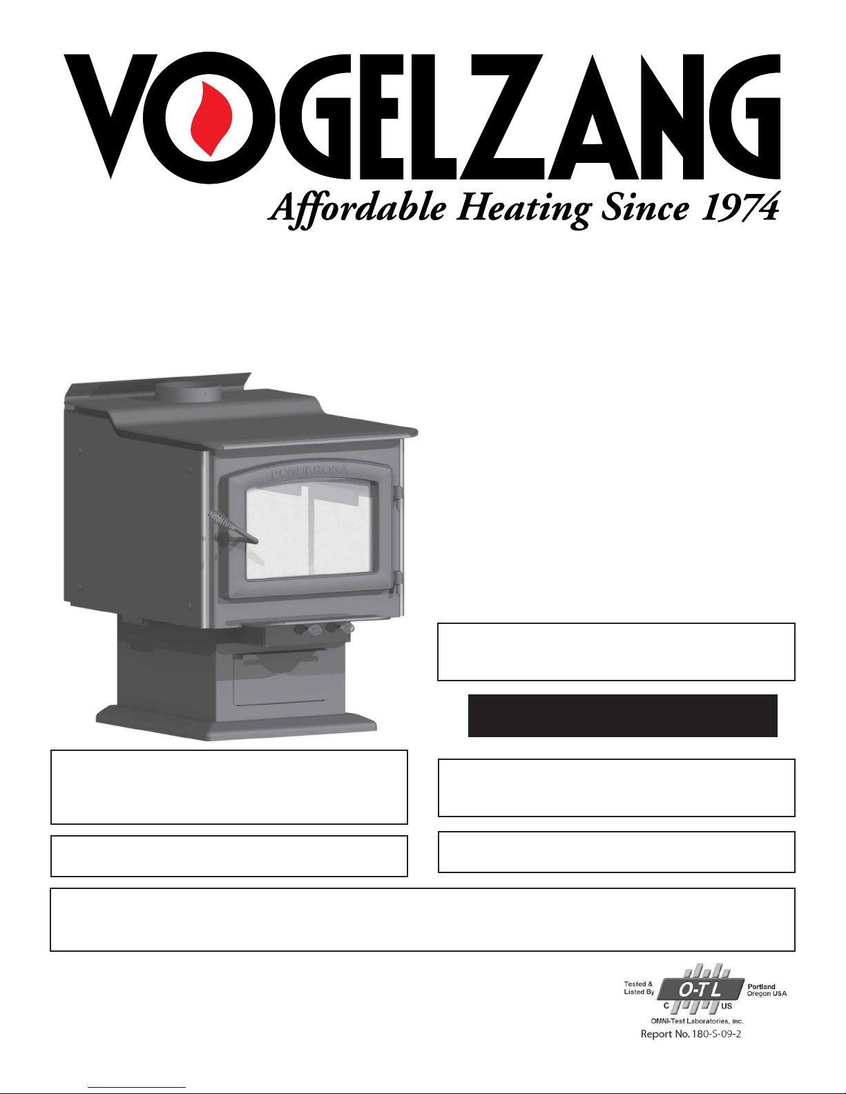
PONDEROSA HIGH-EFFICIENCY WOODSTOVE
Owner’s Manual
Model TR007
EPA Certied (3.20 grams/Hr.)
(Save these Instructions)
Le Manuel de langue francais est disponible a www.
usstove.com / French language manual is available at
www.usstove.com
U.S. Environmental Protection Agency
Certied to comply with 2015 particulate emissions
standards.
READ ALL INSTRUCTIONS CAREFULLY BEFORE
INSTALLING OR OPERATING THIS STOVE. FAILURE TO
FOLLOW INSTRUCTIONS MAY RESULT IN PROPERTY
DAMAGE, BODILY INJURY, OR EVEN DEATH.
REFER TO MARKINGS ON STOVE LABELS FOR
ADDITIONAL INFORMATION.
SAFETY NOTICE: IF THIS STOVE IS NOT PROPERLY INSTALLED, A HOUSE/BUILDING FIRE MAY RESULT. FOR YOUR
SAFETY, CONTACT LOCAL OR MUNICIPAL BUILDING OR FIRE OFFICIALS ABOUT PERMITS, RESTRICTIONS AND
INSTALLATION REQUIREMENTS FOR YOUR AREA.
This stove meets test standards:
US: Ul1482-2011 & CDN: ULC-S627-00
NOTE: IT IS RECOMMENDED INSTALLATION BE
COMPLETED BY A QUALIFIED HEATING EQUIPMENT
INSTALLER!
ROOM HEATER, SOLID FUEL TYPE, ALSO FOR USE IN
MOBILE (USA ONLY)
U.S. Stove Company
227 Industrial Park Road,
South Pittsburg, TN 37380
Phone 1-800-750- 2723
www.usstove.com
852201D-2001G

Safety Instructions
This manual describes the installation and operation of the Vogelzang, TR007 wood heater. This heater meets the
2015 U.S. Environmental Protection Agency’s crib wood emission limits for wood heaters sold after May 15, 2015.
Under specic test conditions this heater has been shown to deliver heat at rates ranging from 11,913 to 34,108
Btu/hr.
Note: The BTU ratings mentioned above are based on the EPA test protocol burning dimensional Douglas Fir
lumber. Our advertised BTU’s are based on the rst hour of operation at high burn rate burning cordwood.
SAFETY INSTRUCTIONS-READ ALL INSTRUCTIONS CAREFULLY
1. The installation of this stove must comply with your local building code rulings. Please observe the clearances
to combustibles (see gures 5–7). Do not place fuel, furniture or any other objects within the clearance area.
2. Verify that the stove is properly assembled and installed before ring the stove for the rst time. After reading
these instructions, if you have any doubt about your ability to complete your installation properly, you must
obtain the services of a professional licensed installer familiar with all aspects of safe and correct installation.
DO NOT use temporary or makeshift compromises during installation. There must be NO DEVIATION OR
ALTERATION OF ANY KIND from the very specic instructions spelled out in this instruction manual as it pertains
to the installation of this woodstove. NO EXCEPTIONS!
3. DO NOT store wood, kindling, ammable liquids or other combustible materials in the vicinity of the appliance.
Refer to certication label on back of unit and reference gures 5–7 in this manual.
4. FOR MOBILE HOME INSTALLATIONS IN U.S.A. ONLY. DO NOT INSTALL THIS STOVE IN A MOBILE HOME,
MANUFACTURED HOME, TRAILER OR TENT NO EXCEPTIONS! (HUD Federal Standard: 24 CFR Ch.XX).
5. DO NOT ELEVATE THIS STOVE BY ANY MEANS. (i.e. bricks under legs, cement blocks) Stove legs must set
directly upon the solid-surface non-combustible oor as specied in this stove instruction manual.
6. DO NOT MODIFY THIS STOVE IN ANY WAY! Stove must be installed with legs and heat shield provided, attached
as shown in the instructions. DO NOT OPERATE WITHOUT BOTTOM HEAT SHIELD IN PLACE – NO EXCEPTIONS.
Assemble only with original parts as supplied and shown in this manual. DO NOT OPERATE A STOVE THAT
IS MISSING ANY PARTS! If any parts are missing or defective, please notify the dealer or manufacturer
immediately. Replace missing, broken or worn parts with factory original or equivalent parts only.
7. CAUTION: DO NOT ALTER COMBUSTION AIR CONTROL RANGE TO INCREASE FIRING OR FOR ANY REASON.
Altering or tampering with air control beyond normal capacity will create unsafe and hazardous conditions.
8. Always connect this stove to a chimney and vent to the outside. Never vent to a room or inside a building.
DO NOT CONNECT THIS UNIT TO A CHIMNEY FLUE SERVING ANOTHER APPLIANCE.
9. DO NOT CONNECT A WOOD BURNING STOVE TO AN ALUMINUM TYPE B GAS VENT. This is not safe. Use codeapproved masonry chimney with ue liner or an Underwriters Laboratories Listed UL 103 HT (US)/ULC-S629
(CDN) Residential Type and Building Heating Appliance Chimney system. Use a 6˝/152mm diameter chimney,
that is high enough to give a good draft. (See specics in Chimney Connections instructions).
10. Be sure that your chimney is safely constructed and in good repair. Have the chimney inspected by the re
department or a qualied inspector. Your insurance company should be able to recommend a qualied
inspector. Chimney connector pipe must be in good condition. Replace if necessary before using stove.
11. Creosote or soot may build up in the chimney connector and chimney and cause a house/building
re. Inspect the chimney connector and chimney twice monthly during the heating season and clean if
necessary. (see Service Hints).
12. In the event of a chimney re, turn the air controls to closed positions, leave the building and CALL THE FIRE
DEPARTMENT IMMEDIATELY! Have a clearly understood plan on how to handle a chimney re by contacting
your local re authority for information on proper procedures in the event of a chimney re. After the re is
out, the chimney must be cleaned and inspected for any stress or cracks before starting another re. Check
the condition of any combustibles surrounding the chimney.
13. Ashes should not be allowed to accumulate above the top of the lower primary air orice (LPAO, air vent at
front of rebox, just inside of door).
14. DISPOSAL OF ASHES Ashes should be placed in a steel container with a tight tting lid and moved outdoors
immediately. The closed container of ashes should be placed on a noncombustible oor or on the ground,
well away from all combustible materials, pending nal disposal. If the ashes are disposed of by burial in
soil or otherwise locally dispersed, they should be retained in the closed container until all cinders have
completely cooled. Other waste shall not be placed in this container.
15. To prevent injury, do not allow anyone to use this stove who is unfamiliar with the correct operation of the
stove.
Note: a licensed professional heating and cooling contractor should be consulted if you have questions
regarding the installation of this solid fuel burning appliance.
-2-

16. Do not operate stove while under the inuence of drugs or alcohol.
17. DO NOT ELEVATE THE FIRE. Build re directly on the bottom of the rebox. This stove has not been tested with
the use of grates, andirons or other means of elevating the re and must not be used.
18. During the rst 12 to 15 res. Additional smoke and odor may be emitted from the light oils used in construction
of the re box. This should disappear after a short period of time and not occur again. Persons with lung
conditions or owners of susceptible domestic pets (such as birds) should take prudent precautions. Open
windows and doors as needed to clear smoke and/or odor. Paint discoloration will occur if the stove is over
red.
19. This stove has a painted surface which is durable but it will not stand rough handling or abuse. When installing
your stove, use care in handling.
20. CLEAN STOVE FREQUENTLY as soot, creosote and ash may accumulate. Clean exterior with soap and warm
water when stove is not hot. Do not use any acids or scouring soap, as these solvents wear and dull the nish.
21. ALERT ALL PERSONS TO THE HAZARDS OF HIGH SURFACE TEMPERATURES while stove is in operation – especially
young children. Keep away from a hot stove to avoid burns or clothing ignition.
22. NEVER LEAVE SMALL CHILDREN UNSUPERVISED WHEN THEY ARE IN THE SAME ROOM AS THE STOVE. If small
children will be in the same room as the stove during operation, provide a sturdy barrier to keep them at a
safe distance from the stove.
23. Keep stove area clear and free from all combustible materials, gasoline, engine oil, naphtha and other
ammable vapors and liquids.
24. WHILE TENDING THE FIRE ALWAYS WEAR PROTECTIVE CLOTHING, re retardant hearth gloves and eye
protection, to prevent burns.
25. Never operate this stove with the door open except when re-fueling. Such actions can result in very dangerous
operating conditions.
26. DO NOT OVER FIRE THE STOVE. Over ring will occur if combustion air is uncontrolled as when feed door is left
open during operation. Such actions can result in very dangerous operating conditions. While in operation,
keep the feed door closed and secured at all times except while tending the re
27. When adding fuel be careful not to smother the re. Do not build res against glass and do not load fuel to
a height or in such a manner that it creates a hazard when opening the door.
28. NEVER LEAVE THE STOVE UNATTENDED with door open. Always close the door after ignition.
29. DO NOT CONNECT TO OR USE IN CONJUNCTION WITH ANY AIR DISTRIBUTION DUCT WORK UNLESS SPECIFICALLY
APPROVED FOR SUCH INSTALLATIONS.
30. A WOOD-BURNING STOVE MUST NEVER BE INSTALLED IN A HALLWAY OR NEAR A STAIRCASE, as it may block
egress in the event of a re.
31. DO NOT INSTALL IN A SLEEPING ROOM. DO NOT INSTALL IN AN ALCOVE OR INSIDE A FIREPLACE.
32. Install at least one smoke detector on each oor of your home. Detectors should be located away from
the heating appliance to avoid false alarms. Detectors should be located close to sleeping areas. Follow
the smoke detectors manufacturer’s placement and installation instructions. Maintain smoke detector per
manufacturer’s instructions.
33. CARBON MONOXIDE (CO) HAZARD. A buildup of CO fumes is toxic and can be fatal. Carbon Monoxide
is a colorless, odorless gas produced during combustion of wood, coal, oil, gas and by other fuel burning
appliances. It is important to have a proper draft and adequate replacement air ventilation so fumes
are drawn out the chimney. Installed as instructed this stove is designed to be as safe as possible yet it is
recommended to install a CO detector. Follow the manufacturer’s recommendations for proper installation
and use. It is recommended to be placed at table-top level (not near the ceiling) to avoid false alarms.
Realize that devices other than a stove (i.e. motor exhaust) can trigger CO alarms.
34. If alarm sounds:
• Recognize the symptoms of CO poisoning (headaches, nausea & drowsiness).
• Increase ventilation (open windows & doors).
• Make sure stove doors and/or lids are closed and secured.
• Check stove for smoking or pufng (open airow controls).
• Check chimney & connector pipe for leaks, blockage or down-draft conditions.
• Check CO device for false alarm.
• Keep power cords, electrical appliances and/or assemblies outside of the clearance area shown in this
manual for combustible materials.
35. Consult your municipal building department or re ofcials about restrictions, permits and installation
requirements for your area.
36. For further information on using your stove safely, obtain a copy of the National Fire Protection Association
(NFPA) publication, “Using Coal and Wood Stoves Safely” NFPA No. HS-10-1978. Write NFPA, Batterymarch
Park, Quincy, MA 02269.
-3-
Assembly Instructions
-
NOTICE: No warranty is granted, stated or implied, for the installation or maintenance of your wood stove
and assumes no responsibility of any incidental or consequential damages.
TOOLS AND MATERIALS REQUIRED FOR INSTALLATION
(NOTE: The following items are NOT included with your stove)
Tools:
• Pencil
• 6 foot Folding Rule or Tape Measure
• Tin Snips
• Drill: Hand or Electric
• 1/8” dia. Drill Bit (for sheet metal screws)
• Screwdrivers (blade and Phillips type)
• 14mm Nut Driver or Ratchet with 14mm Socket
• Safety Glasses
• Gloves
CAUTION: Stove is heavy. Make sure you have adequate help
and use proper lifting techniques whenever moving stove.
1. Uncrate the stove and remove all packing materials and
protective poly bag. Remove the base skirting parts and
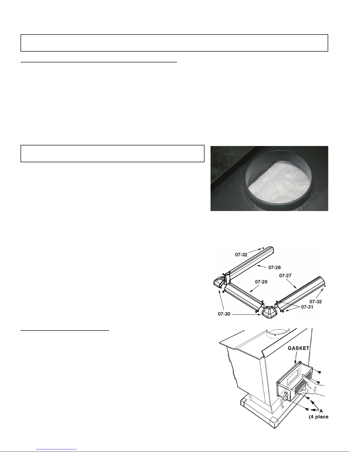
hardware pack from inside the rebox. NOTICE: DO NOT
REMOVE CERAMIC BLANKET material from inside stove pipe
opening (gure 1). This blanket provides an air seal on the
side walls of the stove to direct combustion gasses over the
secondary combustion tubes before exiting via the chimney.
DO NOT REMOVE THE CERAMIC BLANKET or your stove will not
operate properly.
2. Stove may be lightened for positioning by removing re brick.
Note position and arrangement of bricks. Firebrick, Ash Drawer
& Ash Cover MUST be replaced before use. DO NOT USE with
missing or cracked re brick.
3. Assemble the pedestal base skirting (gure 2). Attach two
corner pieces (07-30) to the center section (07-29) of skirting
and secure with four (4) 3/8˝ long truss head sheet metal
screws (07-31).
4. Attach the side skirting sections (07-27 & 07-28) to the corner
pieces and secure with four (4) truss head screws (07-31).
5. Slide the U-shaped skirting assembly around the pedestal base
and secure with two 1/4˝ long pan head sheet metal screws
(07-32) at the rear corners.
Materials:
• Chimney Connector Pipe: 6”/156mm dia. minimum
24 MSG black or 26 MSG blue steel straight stove
pipe or elbow(s).
• 1/2”/13mm Sheet Metal Screws.
• Chimney: Existing 6˝ Code-approved lined masonry
chimney or 6˝ inside dia. manufactured chimney
system listed to UL 103 HT (US)/ULC-S629 (CDN) listed
Furnace Cement (manufacturer recommends
Rutland Code 78 or equivalent)
DO NOT
REMOVE!
Figure 1 – DO NOT remove ceramic blanket
from inside stove pipe opening. This is NOT
packing material but an integral component of
the stove combustion system.
Figure 2
Base Skirting
OPTIONAL BLOWER ASSEMBLY
1. For Optional Blower Assembly, note the position of the blower
opening in the rear of the stove (g. 3).
2. Place blower gasket onto blower assembly so as not to obstruct
the air ow from the fan.
3. Mount the blower assembly to the back of the stove aligning
the fan opening to the opening in the back of the stove.
Secure with four sheet metal screws.
4. After assembly, check to make sure re brick are properly
positioned and ash clean out cover is in place.
5. Route the power cord away from stove. Do not allow the
power cord to touch any hot surfaces. Keep power cord at
least 12˝ from stove surfaces.
6. Once stove is positioned, plug power cord into a grounded
120v outlet.
Figure 3 – Attach
Optional Blower
to Stove Body
-4-
LOCATING STOVE
1. The stove must be placed on solid concrete, solid masonry, or when installed on a combustible oor, on an
Underwriters Laboratories Listed Type 2 oor protector listed to UL standard UL 1618, such as Hy-C or Imperial
Model UL4056BK. Floor protector must be 1/2˝/13mm minimum thickness (R value = 1.19, K value = 0.84 see
page 23 for calculation formulas) non-combustible material or equivalent. The oor protector must extend
at least 18˝/46cm beyond the front of the access door, 8˝/21cm to the sides, 8˝/21cm beyond the rear and
must extend under and 2˝/50mm beyond either side of the stove pipe if it is elbowed towards a wall. (See
gures 4 – 6 and consult local building codes and re protection ordinances.)
CAUTION: Fire hazard. Carpeting and other combustible material shall not cover the oor protector. These
materials must remain outside of combustible clearances, see g. 5 – 7
2. The room in which the stove is installed must have a minimum oor to ceiling height of 8 ft. (2.4 m).
3. The stove must have its own ue. Do not connect this unit to a chimney ue serving other appliances. DO
NOT CONNECT TO ANY AIR DISTRIBUTION DUCT OR SYSTEM.
4. After observing the clearances to combustible materials (gures 4 – 6), locate your oor protector accordingly
(gure 4) and carefully place the stove in your selected location. Install connector pipe, elbows, and
thimble as required, utilizing either a recently cleaned and inspected 6˝/152mm lined masonry chimney or
a 6˝/152mm i.d. manufactured chimney system listed to UL 103 HT (US)/ULC-S629 (CDN).
5. Use round 6˝/152mm dia., minimum 24 MSG black or 26 MSG blue steel stove pipe to connect the stove
to the chimney. Do not use galvanized stove pipe. NOTE: Mobile home installations require double-wall UL
103 HT high-temp connector pipe. Secure connector pipe to the ue collar with three (3) equally spaced
sheet metal screws to rmly hold the pipe sections together. DO NOT CONNECT THIS STOVE TO ANY AIR
DISTRIBUTION OR DUCT SYSTEM.
6. Recheck clearances from the stove, connector stove pipe, and corner clearances using the illustrations in
gures 4 – 6 and your local building codes or re protection ordinances.
NOTE: Any wall containing combustible material such as wooden studs or drywall and faced with brick or
stone must be considered a combustible surface.
7. NOTICE: for installation in a manufactured/ mobile home (USA only), please see specic requirements on
page 10.
8. The clearances provided are minimum dimensions set by US standard UL 1482-2011 & ULC-S627-00, tested
and applied by OMNI-Test Laboratories, Inc. the manufacturer’s testing agency. Installation of this stove
must comply with the latest edition of NFPA 211 (US)/CAN/CSA-B365 (CDN) for reduced clearances and/or
your local building code rulings. Use whichever minimum dimensions are Clearances listed and shown MUST
be adhered to for safe operation of this appliance. CLEARANCES MAY NOT BE REDUCED BY ANY MEANS IN
USA OR CANADA.
9. This stove meets U.S. Test Standard: UL 1482- 2011& Canadian Standard: ULC-S627-00.
CAUTION: Keep furnishings and other combustible materials away from the stove.
NOTE: Before ring woodstove slide rebricks towards the rear so no gaps remain between bricks.
-5-
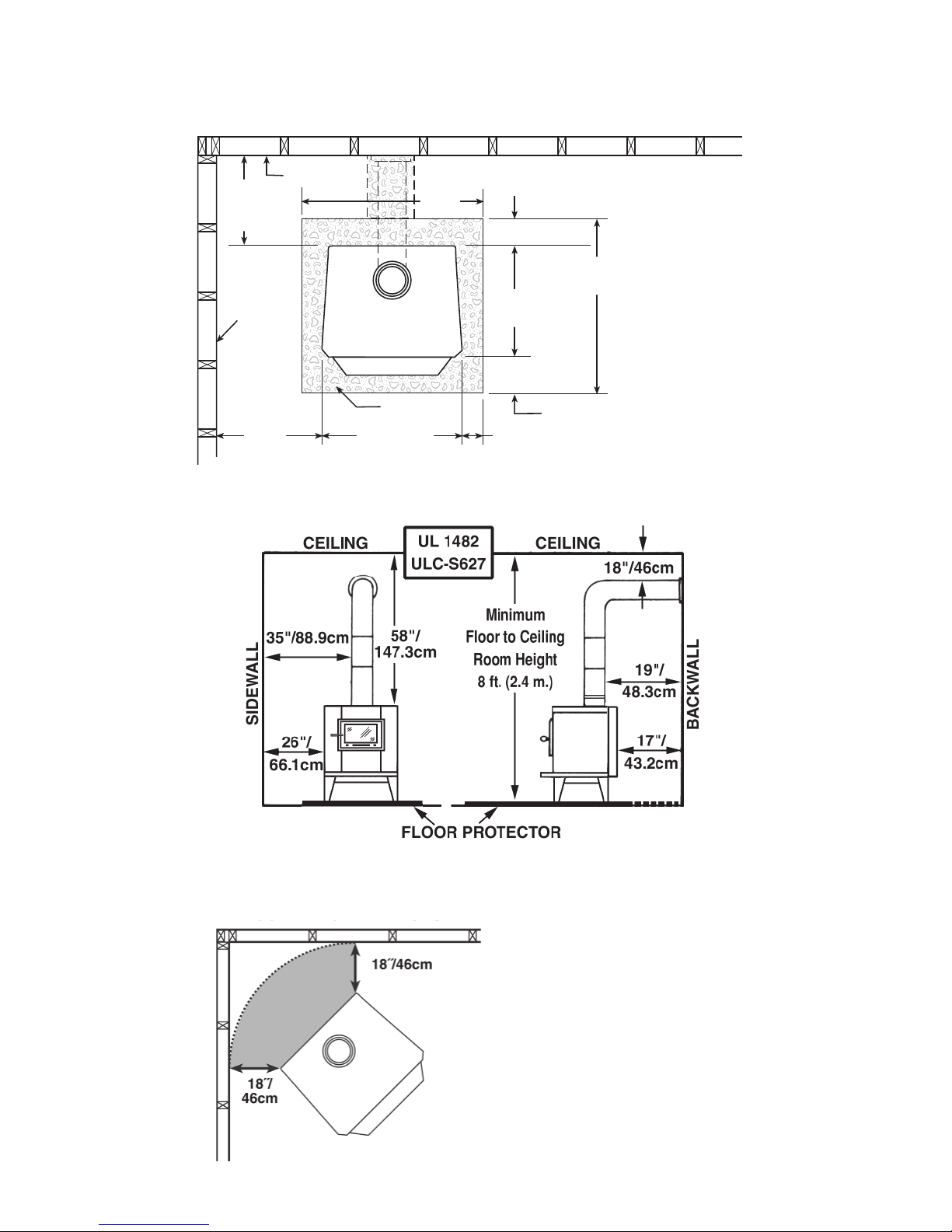
Locating Stove
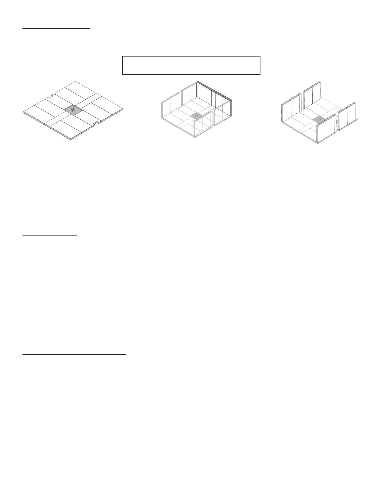
COMBUSTIBLE CONSTRUCTION IN ACCORDANCE WITH US NFPA 211
CLEARANCES | TOP VIEW
17"/
BACKWALL
43.2cm
min
SIDEWALL
26"/66.1cm
min.
Figure. 4 – TOP VIEW Minimum Clearance Dimensions from
Combustible Surfaces
PROTECTOR
24"/61cm
DASHED LINES SHOW HORIZONTAL CHIMNEY CONNECTOR
AND ADDITIONAL FLOOR PROTECTOR REQUIRED BENEATH
40"/
102cm
AND EXTENDING 2"/50.8mm BEYOND
EACH SIDE OF CONNECTOR PIPE
8"/21cm min.
30"/76.2cm
FLOOR
8"/21cm min.
56"/142.3cm
18"/46cm min.
Minimum
Clearances
for installation
according to
UL 1482 (US) &
ULC-S627 (CDN)
Figure 5a – Front View Figure 5b – Side View
Minimum Clearance Dimensions
from Combustible Surfaces
Figure 6 – Top View
Minimum Corner
Clearances from
Combustible Surfaces
18˝/46cm (US & CDN)
-6-
A
A
A
A
XD
A
A
A
A
M
XD
M
A
A
A
A
A
A
A
A
XE
XE
A
A
A
A
XD
A
A
A
A
M
XD
M
A
A
A
A
A
A
A
A
XE
XE
A
A
A
A
XD
A
A
A
A
M
XD
M
A
A
A
A
M
A
A
A
A
A
A
A
A
XE
XE
A
A
A
A
XD
A
A
A
A
M
XD
M
A
A
A
A
A
A
A
A
XE
XE
FIREBRICK ASSEMBLY
Firebrick extends the life of your stove and radiates heat more evenly. Check to see that all rebricks are in their
correct positions and have not become misaligned during shipping or assembly. If removed for ease of locating
stove, rebrick must be replaced before ring. See gures 7a – 7c, for proper positioning.
CAUTION: Never operate stove with
missing or cracked re bricks!
A
A
A
XD
A
M
A
M
XD
A
A
A
Figure 7a – Step 1, Bottom
Firebrick Arrangement
Eight (8) A-size, Two (2) M-size,
Two (2) XD-size
Fire Brick Dimensions (inches)
A-size: 9˝x4½˝x1¼˝
M-size: 9˝x2¼˝x1¼˝
XD-size: 8˝x4½˝x1¼˝†
XE-size: 9¾˝x1½˝x1¼˝
† XD bricks have offset notches to accommodate air tube side supports – see illustrations
XE
A
A
A
A
Figure 7b– Step 2, Side
Firebrick Arrangement Four
(4) A-size, Two (2) M-size
A
XD
M
A
A
A
M
A
A
A
M
XD
A
A
A
A
A
A
A
A
A
XE
Figure 7c– Step 3, Back
Firebrick Arrangement Four
(4) A-size, One (1) M-size
CHIMNEY SIZING
Today’s solid fuel heating appliances are much more efcient than those made in the past. Your heating
appliance has been designed to provide the most efcient transfer of heat possible from the least amount of fuel.
Controlled combustion is the key to optimum heating performance. Controlled combustion requires a ow of
fresh air into the appliance, across the fuel and is nally exhausted up the chimney. Today’s high efciency stoves
transfer more heat into the living area and less up the chimney. Exhaust gases are typically at a lower temperature
than traditional type stoves. With lower exhaust temperatures, it is important that the chimney is correctly sized to
the stove. If the chimney diameter is too large, it will be difcult to raise the chimney ue temperature to provide
for adequate draft. This may result in a poor burn, smoke spillage, and rapid creosote creation. A 6”/152mm
diameter chimney is best suited for this stove. Your heating appliance must have a minimum of a 6”/152mm
diameter chimney. Maximum chimney diameter must not exceed 10˝ /254mm or have a cross sectional area
greater than 85 sq. in. /550cm2. Proper draft for this heating appliance is minimum of 0.05 w.c. (water column
measurement) and is required to prevent back pufng, smoke spillage and prevent safety hazards. Take into
account the chimney’s location to insure it is not too close to neighbors or in a valley which may cause unhealthy
or nuisance conditions.
IMPORTANCE OF PROPER DRAFT
Draft is the force which moves air from the appliance up through the chimney. The amount of draft in your
chimney depends on the length of the chimney, local geography, nearby obstructions and other factors. Too
much draft may cause excessive temperatures in the appliance. Inadequate draft may cause backpufng into
the room and ‘plugging’ of the chimney.
Inadequate draft will cause the appliance to leak smoke into the room through appliance and chimney
connector joints. An uncontrollable burn or excessive temperature indicates excessive draft.
-7-
Connector Pipe Installation
NOTE: Connector pipe is not included. To purchase, visit your local hardware, home, or building center. See
“locating stove” page 6 for additional specications.
Connector pipe is used to make the connection from the nal positioning of your stove to an approved chimney.
Connector pipe is NOT included as part of the stove. Connector pipe must be 6”/152mm diameter minimum of
24 MSG (minimum standard gauge) black or 26 MSG blue steel stove pipe.
NOTICE: For mobile home installations (US only), connector pipe must be double-wall, high-tempurature pipe
that meets ul 103 ht specications.
Any connector pipe used must be in good condition. Replace if necessary before using stove. Connector pipe is
not rated to provide close contact to combustible materials and must have proper clearance from combustible
materials as shown in the clearance diagrams on the previous pages. Connector pipe should never be used in
place of a chimney. If proper clearances are not observed a house re could result.
INSTALLATION INSTRUCTIONS
Please Note: Installation of a ue damper is NOT recommended. Combustion control is regulated by the intake
of combustion air, not the exhaust.
1. The crimped end of the stovepipe ts inside the stove ue collar. Secure with three (3) equally spaced sheet
metal screws. The rst section of connector pipe must be single walled to properly attach to the stove collar.
Install additional pipe and elbow with the crimped end towards the stove. This will allow any condensation
in the ue to run back into the rebox.
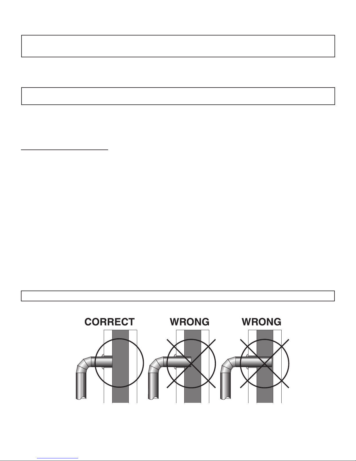
2. Horizontal pipe runs must slope upwards towards the chimney at least 1/4˝/6.4mm per foot of horizontal run.
3. You must have at least 18˝/457mm of clearance between any horizontal piping and the ceiling.
4. The pipe cannot extend into the chimney ue (gure 8).
5. Secure all pipe/elbow sections with three (3) equally spaced sheet metal screws at each joint to make the
piping rigid. DO NOT CONNECT THIS STOVE TO ANY AIR DISTRIBUTION DUCT OR SYSTEM.
6. It is recommended that no more than two (2) 90° bends be used in the stovepipe installation. The use of
more than two 90° bends may decrease the amount of draw and possibly cause smoke spillage. Where
possible, use only corrugated (non adjustable) elbows. These provide a better seal.
7. The connector pipe must not pass through an attic or roof space, trusses, closet, or any concealed space,
oor, ceiling, wall, or combustible construction. (See Chimney Connector Systems & Clearances, page
13.) A manufactured chimney system listed to UL 103 HT (US)/ULC-S629 (CDN) must be used from the rst
penetration of ceiling or wall to the chimney cap. Where passage through a wall or partition of combustible
construction is desired, the installation shall conform to NFPA 211 (USA) or CAN/CSA-B365 (Canada).
WARNING: Do not use single wall connector pipe as a chimney - a house re could result.
Figure 8 – Stovepipe/Flue Connections
-8-
Mobile Home Installation Instructions
This stove is approved for mobile home installation
in the USA only (DO NOT INSTALL IN MOBILE HOMES
IN CANADA). In addition to the installation and
safety instructions, the following requirements are
MANDATORY for installation in a mobile home.
All mobile home installations must be made in
accordance to Manufactured Home and Safety
Standard (HUD), CFR 3280, part 24.
1. The stove must be permanently bolted to
the oor to prevent movement of the stove.
Movement of the stove could separate the
outdoor air connection and/or chimney
connection and create an unsafe operating
condition.. Examine oor structural members
to make sure that the weight of the installation
can be supported.
2. CAUTION: THE STRUCTURAL INTEGRITY OF THE
MOBILE HOME FLOOR, WALL, AND CEILING/
ROOF MUST BE MAINTAINED.
3. The stove must be electrically grounded to
the steel frame of the Mobile Home. The stove
must be grounded using a #8 ga. ground wire
with approved termination and star washer.
4. The oor protection and specied clearances
noted elsewhere in this manual must be
maintained.
5. The unit must have a permanent outside air
source for combustion. The combustion air
intake system must be of metal construction.
Minimum diameter for the intake ducting is
5 inches. The air intake must be screened to
prevent the entrance of rodents. The outside
air inlet must be kept free of leaves, snow, ice,
or other debris that could restrict air supply
when the appliance is in operation. Fresh Air
Kit Model FAK-07 is compatible with this unit.
Kit is available at www.vogelzang.com or
your local retailer.
6. WARNING: DO NOT INSTALL IN A SLEEPING ROOM.
7. WARNING: DO NOT USE SINGLE WALL CONNECTOR PIPE ANYWHERE IN A MOBILE HOME INSTALLATION. A
listed double-wall chimney connector system, ceiling thimble, roof thimble, spark arrestor, and roof ashing
suitable for use in Mobile Homes must be used. All components of the chimney and connector system must
be of the HT type and listed to UL 103 HT. Install per chimney manufacturer’s instructions.
8. The openings in the chimney cap must not permit the entrance of a 3/4˝/19mm diameter rod.
9. If the chimney exits the Mobile Home at a location other than through the roof, and exits a point 7 ft. /21.3m
or less above the ground upon which the Mobile Home is set upon, a guard shall be tted at the point of exit
up to 7 ft./21.3m.
10. The chimney shall be attached directly to the room heater and shall extend at least 3 ft./91.4cm above the
part of the roof through which it passes. The top of the chimney must project at least 2 ft./60.1cm above the
highest elevation of any part of the Mobile Home within 10 ft./3.1m of the chimney.
11. Use silicone to seal at the location where the chimney and fresh air supply system penetrates the exterior of
the structure.
12. The chimney system must comply with all local requirements.
Figure 9 – Mobile Home Installation
-9-
Chimney Connections
CHIMNEY
FLUE
5/8" TILE
CHIMNEY
LINER
MASONRY
CHIMNEY
THIMBLE
COLLAR
8˝ MIN.
LINER
BELOW
ENTRY
HOLE
The stove must be connected to either a lined masonry or manufactured metal chimney built and tested to the
specications listed on the previous pages.
Chimneys perform two functions:
1. As a means of exhausting smoke and ue gases which are the result of fuel combustion.
2. The chimney (only) provides “draft” which allows oxygen to be continuously introduced into the appliance,
so that proper combustion is possible. This stove relies on natural draft to operate.
NOTICE: Always provide a source of fresh air into the room where the stove is located. Failure to do so may result
in air starvation of other fuel burning appliances and the possible development of hazardous conditions.
A stove DOES NOT create draft. Draft is provided by the chimney. To achieve proper draft your chimney must
meet the four minimum height requirements detailed in gures 11–13. If these minimum requirements are not met
your stove will not operate properly. A minimum of 0.05 w.c. (measured in water column) is required for proper
drafting to prevent back pufng, smoke spillage, and to maximize performance. (Gauges to measure draft are
readily available at stove stores and are economical to rent or purchase.) Factors such as wind, barometric
pressure, trees, terrain and chimney temperature can have an adverse effect on the draft. The manufacturer
cannot be held responsible for external factors leading to less than optimal drafting. Should you have a problem
with inadequate draft, you should contact a licensed heating and cooling contractor for assistance in solving the
problem. For a more in-depth explanation see Chimney Draft.
IMPORTANT INSTALLATION POINTS
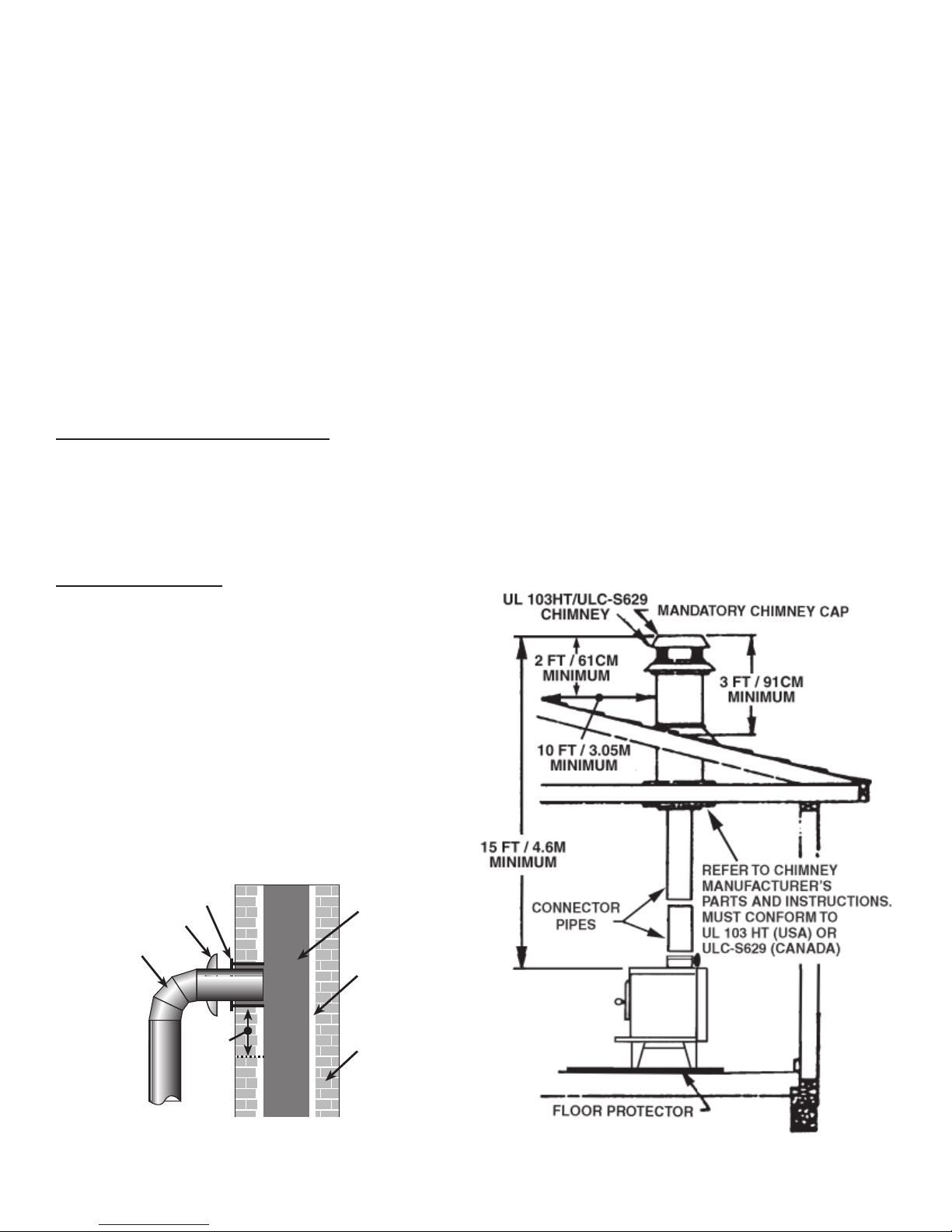
1. Size chimney ue to stove collar. This stove requires a minimum of a 6”/152mm diameter ue.
2. Never connect this unit to a chimney serving another appliance.
3. The chimney must meet all minimum height requirements.
4. Never use a chimney to ventilate a cellar or basement.
5. Contact your local building authority for approved methods of installation and any necessary permits and/
or inspections.
MASONRY CHIMNEY
The chimney must be a code-approved, masonry
chimney with ue liner. Before using an existing
masonry chimney, clean the chimney, inspect the
ue liner and make any repairs needed to be sure
it is safe to use. Make repairs before attaching the
stove. The connector stove pipe and ttings you will
need to connect directly to a lined masonry chimney
are shown in gure 10. If the connector stove pipe
must go through a combustible wall before entering
the masonry chimney, consult a qualied mason or
chimney dealer. The installation must conform to local
building and re codes and latest edition of NFPA 211
US or CAN/CSA-B365. If there is a clean out opening in
the base of the chimney, close it tightly.
CHIMNEY
FLUE
5/8" TILE
CHIMNEY
LINER
6˝ ROUND
24 ga. BLACK
CONNECTOR
STOVEPIPE
THIMBLE
COLLAR
8˝ MIN.
LINER
BELOW
ENTRY
HOLE
Figure 10 - Masonry Chimney Connection
MASONRY
CHIMNEY
Figure 11 - Chimney Construction through Attic Space
-10-
MANUFACTURED CHIMNEY
REFER TO CHIMNEY AND CHIMNEY CONNECTOR MAKER’S
INSTRUCTIONS FOR INSTALLATION AND USE.
Use only 6˝/152mm diameter manufactured chimney
system listed to UL 103 HT (US) or ULC-S629 (CDN).
Chimney made to this listing is High Temperature rated to
2100°F/1149°C. Use chimney from only one manufacturer.
Never mix brands. Carefully follow the chimney
manufacturer’s stated requirements and clearances.
Use the chimney manufacturer’s attic guards, roof
supports, ashing and re stops when passing through a
ceiling. Use a listed wall pass-thru when passing through
a combustible wall. Do not use makeshift compromises
during installation.
WARNING: DO NOT USE A SINGLE-WALL CONNECTION
PIPE AS A CHIMNEY!
When using a pre-existing chimney, have its condition
and installation inspected before using. Make sure that
the chimney meets all of the UL rating requirements listed
above. Be aware that not all manufactured chimney is
UL 103 HT/ULC-S629 rated. NOTE: It is recommended that
you contact a licensed heating and cooling contractor
(consult your local yellow pages) for chimney installation.
Manufactured chimney with the proper required UL/ULC
listing is available from most home centers, hardware
stores, and HVAC supply stores. You may wish to view
chimney manufacturers’ information on-line. See, www.
duravent.com, www.selkirkinc.com or www.mtlfab.com.
VENTING TO EXISTING FIREPLACE
In some instances, people desire to convert an existing
replace for stove use. Usually, safe connection to an
existing masonry chimney requires more work than using
a prefabricated chimney. The existing replace must be
closed and sealed at the damper with high-temperature
caulk, ceramic wool, or furnace cement. Prior to
installation, clean and inspect the existing ue and smoke
shelf. Installation should be designed so the system can
be dismantled for periodic cleaning and inspection.
Before conversion, make sure the existing chimney is
structurally sound, the chimney incorporates a ue liner
and make sure it is in good condition. (A ue liner consists
of clay tile that protects the brickwork of a chimney. If a
chimney does not have a liner, or it is damaged, have it
relined by a professional. Do Not use a chimney that is
unlined or damaged! If you have any question regarding
the condition of the chimney, consult a qualied licensed
contractor, qualied engineer, competent mason, cer
tied Chimney Sweep, or a knowledgeable inspector.
Consult your insurance company if you cannot nd a
qualied expert.
Chimney Minimum Height Requirements:
1. Overall Height – 15 ft./4.6m min.
2. Height above roof – 3 ft./91cm
3. Height above slope – 2 ft./61cm min. within 10
ft./3.05m
4. Minimum rise before horiz. section – 24 in./61cm
NOTICE: If minimum chimney requirements are not
met, your stove will not operate properly.
Figure 13 - Chimney Connection to
Firebox through Masonry Wall
-11-
CAUTION: Not all replace chimneys are suitable for conversion to accommodate connection to a wood
stove. Check with a qualied expert.
Many prefabricated replaces are of the “zeroclearance replace” category. These consist of multi layered
metal construction. They are designed with enough insulation and/or air cooling on the base, back and sides so
they can be safely installed in direct contact with combustible oors and walls. Although many prefabricated
replaces carry endorsements from nationally recognized organizations for use as replaces, they have not been
tested for connection to wood stove heaters. Connecting a stove to such a device will void the manufacturer’s
warranty. Venting a stove directly into a replace does not meet code and should not be attempted. The stove
warranty will be void with such an installation. Do not create a hazard in your home by connecting in this manner.
FIREPLACE INSTALLATION
NOTE: DO NOT ATTEMPT TO ROUTE THE CHIMNEY CONNECTOR PIPE THROUGH THE THROAT OF THE FIREPLACE.
Directly connecting the stovepipe into the existing masonry chimney (gure 14 “Type A” Fireplace Conversion) of
the replace is the ONLY approved method of installation. If the chimney is behind a combustible wall, you must
use an approved wall passthrough system to gain access to the chimney. This is a complicated and involved
process and to ensure safety should only be done by a qualied installer.
1. An entry hole must be cut through the masonry and tile liner with minimal damage to the liner. At least
8˝/203mm of liner must remain below the entry position. When locating the stove and stovepipe, all minimum
clearances must be observed from combustible surfaces including mantels, combustible trim work, ceilings,
and walls. Positioning the center of the stove pipe entry into the chimney 24˝/61cm below the ceiling should
insure proper clearance for a 6˝/152mm stovepipe.
2. Install a re clay (5/8˝/16mm minimum thickness) thimble. Make sure the thimble is ush with the inner surface
of the chimney liner and does not protrude into the ue (see gure 9 on page 9).
3. Secure the thimble with refractory mortar. The thimble should be surrounded by 12˝/305mm of solid unit
masonry brickwork or 24˝/61cm of stone.
4. Install the stovepipe into the thimble as far as possible without extending past the ue lining.
5. A small airspace (about 1/2˝/13mm) should remain between the stovepipe and thimble to allow for
expansion of the pipe. Seal this airspace with high temperature caulking or ceramic wool.
6. Secure and seal the damper in the closed position using high-temp caulking, ceramic wool, or furnace
cement. Also check to see if the chimney has a clean out.
If it does, make sure it is closed and sealed as well. A leaky clean out will greatly reduce draft efciency. If
you have any questions regarding venting your stove, contact the manufacturer or contact the National Fire
Protection Association (NFPA) and request a copy of the latest editions of NFPA Standard 211 and NFPA Standard
908. Their address is: Battery March Park, Quincy, MA 02269.
Figure 14 - Fireplace Conversion
-12-
CHIMNEY CONNECTOR SYSTEMS & CLEARANCES
NFPA 211 (US) NOTE: In Canada, installation must
conform to CAN/CSA-B365 when passing through
combustible construction.
A. Brick Masonry - Minimum 3.5˝/89mm thick brick
masonry all framed into combustible wall with a
minimum of 12˝/305mm brick separation from
clay liner to combustibles. The reclay liner shall
run from outer surface of brick wall to, but not
beyond, the inner surface of chimney ue liner
and shall be rmly cemented in place.
B. Insulated Sleeve - Solid-insulated, listed factory-
built chimney length of the same inside
diameter as the chimney connector and having
1˝/25.4cm or more of insulation with a minimum
9˝/229mm air space between the outer wall of
the chimney length and combustibles.
C. Ventilated Thimble - Sheet steel chimney
connector, minimum 24 gauge in thickness,
with a ventilated thimble, minimum 24 gauge in
thickness, having two 1˝/25.4mm air channels,
separated from combustibles by a minimum
of 6˝/152mm of glass ber insulation. Opening
shall be covered, and thimble supported with
a sheet steel support, minimum 24 gauge in
thickness.
D. Chimney Section Pass-through - Solid insulated,
listed factory-built chimney length with an inside
diameter 2˝/51mm larger than the chimney
connector and having 1˝/25.4mm or more
of insulation, serving as a pass-through for a
single wall sheet steel chimney connector of
minimum 24 gauge thickness, with a minimum
2˝/51mm air space between the outer wall of
chimney section and combustibles. Minimum
length of chimney section shall be 12˝/305mm
chimney section spaced 1˝/25.4mm away from
connector using sheet steel support plates on
both ends of chimney section. Opening shall
be covered, and chimney section supported
on both sides with sheet steel support securely
fastened to wall surfaces of minimum 24 gauge
thickness. Fasteners used to secure chimney
section shall not penetrate chimney ue liner.
-13-
Operating Instructions
Caution: House Fire Hazards
• Do not store wood on oor protector, underneath stovepipe or anywhere within minimum clearances from
combustible surfaces specied for this stove.
• Overring may cause a house re. You are overring if a unit or chimney connector glows red.
OPERATING SAFETY PRECAUTIONS
1. Never overre this stove by building excessively hot res as a house/ building re may result. You are overring
the stove if unit or stovepipe begins to glow or turn red.
2. Never build extremely large res in this type of stove as damage to the stove or smoke leakage may result
3. Do not build re too close to glass.
4. Unit is hot while in operation. Keep children, clothing, and furniture away. Contact may cause skin burns. Do
not touch the stove after ring until it has cooled.
5. Provide air into the room for proper combustion.
6. Inspect stovepipe every 60 days. Replace immediately if stovepipe is rusting or leaking smoke into the room.
7. Attempts to achieve heat output rates that exceed heater design specications can result in permanent
damage to the heater.
THIS STOVE IS DESIGNED TO BURN NATURAL WOOD FUEL ONLY!
Warning: Explosion Hazard
• Never use chemicals, gasoline, gasoline-type lantern fuel, kerosene, charcoal lighter uid, or similar
ammable liquids to start or “freshen-up” a re in the stove.
• Keep all ammable liquids, especially gasoline, out of the vicinity of the stove— whether in use or in
storage.
Hardwood, 18˝ to 20˝ / 45cm to 50cm should be air dried (seasoned), for a minimum of 6 months. Logs grater
than 6˝/152mm in diameter should be split. Wood should be stored in a dry, well ventilated area. The humidity
content for usable rewood must be less than 20% of the weight of the log. This heater is designed to burn natural
wood only. Higher efciencies and lower emissions generally result when burning air dried seasoned hardwoods,
as compared to softwoods or to green or freshly cut hardwoods.
Attempts to use wet or unseasoned wood will cause:
- ignition problems - rapid creosote build-up resulting in chimney re
- incomplete combustion - low heat yield
- blackened glass
DO NOT BURN:
1. Garbage;
2. Lawn clippings or yard waste;
3. Materials containing rubber, including tires;
4. Materials containing plastic;
5. Waste petroleum products, paints or paint thinners,
or asphalt products;
6. Materials containing asbestos;
7. Construction or demolition debris;
8. Railroad ties or pressure-treated wood;
9. Manure or animal remains;
Burning these materials may result in release of toxic fumes or render the heater ineffective and cause smoke.
Dead wood lying on the forest oor should be considered wet, and requires full seasoning time. Standing dead
wood can usually be considered to be about 2/3 seasoned. Splitting and stacking wood before it is stored
accelerates drying time. Storing wood on an elevated surface from the ground and under a cover or covered
area from rain or snow also accelerates drying time. A good indicator if wood is ready to burn is to check the
piece ends. If there are cracks radiating in all directions from the center then the wood should be dry enough
to burn. If your wood sizzles in the re, even though the surface is dry, it may not be fully cured, and should be
seasoned longer.
10. Salt water driftwood or other previously salt water
saturated materials;
11. Unseasoned wood; or
12. Paper products, cardboard, plywood, or
particleboard. The prohibition against burning
these materials does not prohibit the use of re
starters made from paper, cardboard, saw dust,
wax and similar substances for the purpose of
starting a re in an affected wood heater.
-14-

Notice: Use solid wood materials only. Do not burn garbage or ammable uids such as gasoline, naphtha
or engine oil. Do not use coal. This stove is not designed to accommodate the air ow (draft) necessary to
properly burn coal or coal products. Do not elevate re or use grates or andirons. Build re directly on bottom
of rebox.
OPTIMAL FUEL CONSUMPTION
This stove is designed to get the most efcient transfer of heat energy from the wood fuel and radiate it into your
living environment. The re box introduces combustion air through four sources. (1) Immediately beneath the door
opening below the window is a Lower Primary Air Orice (LPAO). (2) The primary air inlet control (center control
lever) brings air into the rebox and controls the rate of burn (and the amount of heat the stove radiates). (3)
The high burn duct control (right control lever) provides additional air for maximum burn rate. (4) The secondary
air tubes at the top of the rebox are designed to ignite the combustion gases (smoke) given off by the burning
wood and increases the efciency of the stove and reduces chimney emissions. Smoke given off by burning
fuel consists of very small organic liquid droplets. If these droplets condense, they form a sticky tar-like substance
called creosote. When operated properly, this stove is designed to burn these droplets. Burning these droplets
releases heat that would otherwise be lost up the chimney as smoke. Following the instructions below will help
you operate your stove properly to maximize the stove’s performance. Actual performance is dependent on
chimney height, weather, log size, wood species and moisture content. Some experimentation will initially be
required to nd that “sweet spot” where your stove performs best. The following will give you a starting point to
nd your optimum settings.
TAMPER WARNING
This wood heater has a manufacturer-set minimum low burn rate that must not be altered. It is against federal
regulations to alter this setting or otherwise operate this wood heater in a manner inconsistent with operating
instructions in this manual.
EFFICIENCIES
Efciencies can be based on either the lower heating value (LHV) or the higher heating value (HHV) of the fuel.
The lower heating value is when water leaves the combustion process as a vapor, in the case of woodstoves the
moisture in the wood being burned leaves the stove as a vapor. The higher heating value is when water leaves
the combustion process completely condensed. In the case of woodstoves this would assume the exhaust gases
are room temperature when leaving the system, and therefore calculations using this heating value consider
the heat going up the chimney as lost energy. Therefore, efciency calculated using the lower heating value of
wood will be higher than efciency calculated using the higher heating value. In the United States all woodstove
efciencies should be calculated using the higher heating value.
The best way to achieve optimum efciencies is to learn the burn characteristic of you appliance and burn wellseasoned wood. Higher burn rates are not always the best heating burn rates; after a good re is established a
lower burn rate may be a better option for efcient heating. A lower burn rate slows the ow of usable heat out
of the home through the chimney, and it also consumes less wood.
When rst loading fuel set the primary air inlet control (center) at the wide open (push in) position for at least
15–20 minutes (the high burn duct control should be closed – pulled out – when starting res). When the stove is
working properly you should be able to observe secondary combustion ames above the fuel pieces in front of
the secondary air tubes at the top of the rebox. These secondary ames should continue to burn after the primary
air inlet is reset from wide open to the desired operating setting. If the ames do not continue to burn, open the air
control to re-establish the secondary ames then slowly reset the air control to the desired setting. Initially it may
take several attempts to gure your stove out. But once you nd the operating “sweet spot” and the correct mix
of procedures to get there, only minor adjustments will be necessary. The best indicator of a properly operating
stove is to look for smoke coming out of the chimney. You may see steam emissions that will quickly dissipate.
Smoke will thin but continue to drift without totally disappearing. If you do detect smoke emissions, open the air
control a little bit, let the stove adjust for 10–15 minutes and re-check your chimney. Remember – visible smoke
represents lost heat.
NOTICE - INITIAL BURNS TO CURE PAINT BECAUSE OF THE HIGH OPERATING TEMPERATURES, THIS STOVE USES A
SPECIAL HIGH-TEMP PAINT WHICH REQUIRES A SERIES OF BURNS TO CURE THE PAINT FOR DURABILITY AND A LIFETIME
OF SERVICE.
Proper curing of the high-temp paint requires a series of three initial burns. The stove should be allowed to cool
off between each burn. The rst two burns should be small res and low temperatures (250°F/120°C) for a duration
of 20 minutes each. The third re should be at a medium-high temperature (500 to 700°F/260 to 370°C) for twenty
minutes. Provide adequate cross ventilation to clear any smoke or odor caused by initial rings.
-15-
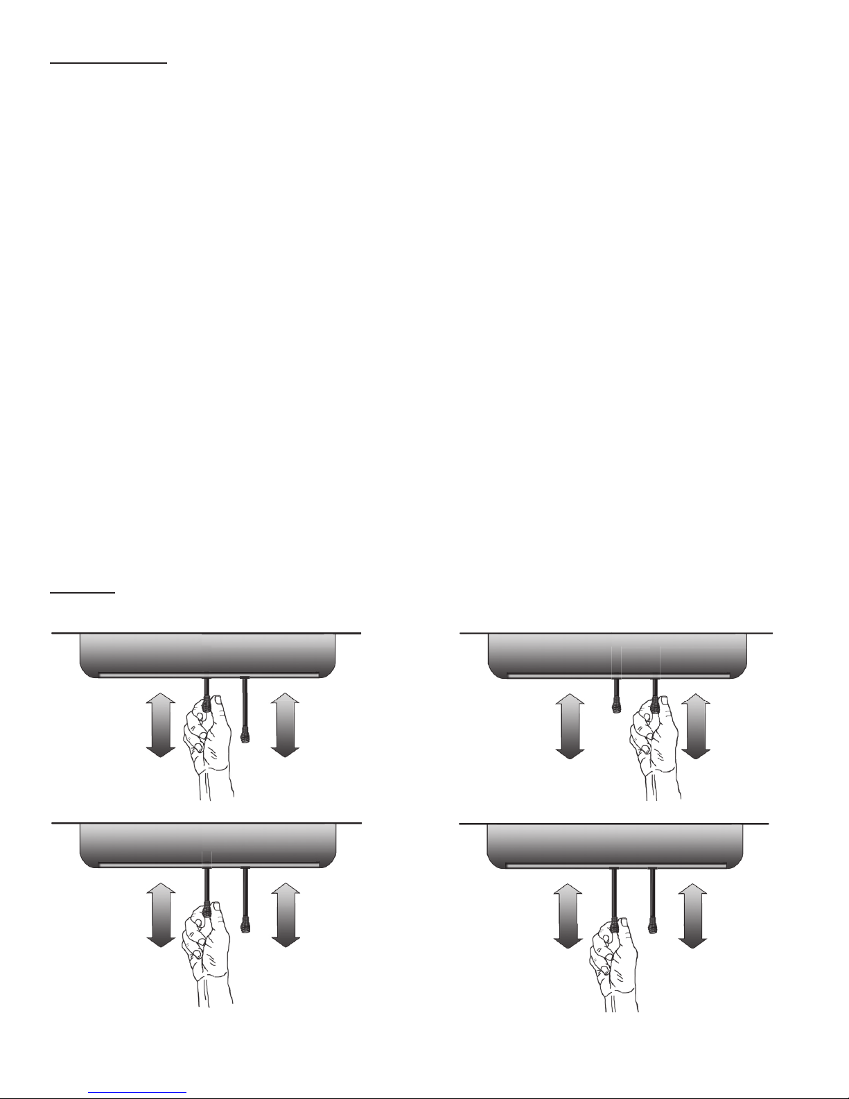
STARTING A FIRE
CONTROL
LEVER
A
(Primary Air)
CONTROL
LEVER
B
(High Burn)
OPEN
CLOSED
OPEN
CLOSED
HEARTH
CONTROL
LEVER
A
(Primary Air)
CONTROL
LEVER
B
(High Burn)
OPEN
CLOSED
OPEN
CLOSED
HEARTH
DO NOT LEAVE STOVE UNATTENDED WITH DOOR OPEN! The top down method of re building is recommended
for this appliance. After making sure that the stove air intake controls are fully open (completely pull-out towards
you), Place the largest pieces of wood on the bottom, laid in parallel and close together. Smaller pieces are
placed in a second layer, crossways to the rst. A third layer of still smaller pieces is laid crossways to the second,
this time with some spaces between. Then a fourth layer of loose, small kindling and twisted newspaper sheets
tops off the pile.
Add large pieces of wood as the re progresses being careful not to overload. (Do not ll rebox beyond rebrick
area.) An ideal coal bed of 1˝ – 2˝ (25mm - 50mm) should be established to achieve optimum performance.
This unit is designed to function most effectively when air is allowed to circulate to all areas of the rebox. TIP: If
ash or coals remain in the stove, make sure to clear them away from the Lower Primary Air Orice (LPAO) and
rake a slight (1˝ – 2˝/25mm-50mm wide) trough down the center of the coal bed from front to back prior to
loading the fuel. Once fuel has been loaded, close the door and leave the air inlet control fully open until re is
well established (at least 15–20 minutes) being careful not to over re (if any of the exterior parts of the stove or
chimney connections begin to glow you are over ring the stove). Re-adjust the primary air inlet control (A) to
desired burn rate. For “low” setting pull the primary air control (center control) all the way out, for “high” push
all the way back. (If excessive smoke lls the rebox, open air inlet control slightly until ames resume and wood
is sufciently ignited.) The basic rule of thumb is “closed (pull out) = low,” “half way open = medium” and “fully
open (push in) = high.” The high burn control lever (B) is used to deliver additional air to an established re when
the primary control is set at 3⁄4 to fully open (all the way in) position. Push the secondary (right) control in to open/
high burn position. When adjusting the primary air to a lower setting, close (pull out) the high burn (right, 3/4 lever)
by pulling control fully out.
1. Set Primary Air Inlet Control Lever “A” to fully open by pushing the center control lever (located under hearth
plate) inward toward the rear of stove. Set the Secondary Air (High Burn) Control Lever “B” to the closed
position by pulling the lever fully out. NOTE: OPEN/HIGH = IN; CLOSED/LOW = OUT (see iIlustrations below)
2. Open the feed door and place several wads of crushed paper in the rebox. Cover the paper with a few
pieces of small kindling wood.
3. Ignite the paper and leave the door slightly open until the kindling re is established. Close and secure the
door. DO NOT LEAVE STOVE UNATTENDED WITH THE DOOR OPEN! Slowly add additional wood, adding larger
pieces as the re progresses.
4. Once the re is fully established you may select the desired burn rate. Be careful not to over re the stove.
SETTINGS
CONTROL
LEVER
A
(Primary Air)
CONTROL
LEVER
A
(Primary Air)
OPEN
CLOSED
OPEN
CLOSED
HEARTH
HEARTH
OPEN
CLOSED
OPEN
CLOSED
CONTROL
LEVER
B
(High Burn)
CONTROL
LEVER
B
(High Burn)
CONTROL
LEVER
A
(Primary Air)
CONTROL
LEVER
A
(Primary Air)
OPEN
CLOSED
OPEN
CLOSED
HEARTH
HEARTH
OPEN
CLOSED
OPEN
CLOSED
CONTROL
LEVER
B
(High Burn)
CONTROL
LEVER
B
(High Burn)
-16-

ADDING FUEL
If the coal bed is not hot and glowing, rake the coals to the front of the stove, close the door and adjust the
primary air inlet control to the wide open position. Let the coals re-heat for 10–15 minutes. When hot and glowing,
spread them out and place your next fuel load into the stove (make sure no coals or ashes block the LPAO).
Leave the primary air inlet control in the wide open (pushed in) position for 15–20 minutes. Fuel load size can vary
but should be kept 1–2˝
(25mm-50mm) below the secondary air tubes. Also position the fuel to leave space so the air from the inlet can
work between the pieces of fuel. This reduces the time it takes for new fuel to burn properly.
1. When refueling, adjust primary air inlet (center) control to the fully open (pushed in) position. When re
brightens, slowly and carefully open the door. This procedure will prevent unburned gases from igniting
causing smoke and ame spillage.
2. When adding fuel be careful not to hit, bump or damage the ceramic bafe board located at the top of
the rebox.
3. Add fuel being careful not to overload or over re the stove.
4. When adding fuel be careful not to smother the re. Do not build res against glass and make sure the coal
bed does not obstruct the air inlet. Do not load fuel to a height or in such a manner that it creates a hazard
when opening the door.
5. Close the feed door and secure tightly.
6. Adjust the air inlet control as described above.
7. Empty ashes regularly. Do not allow ashes to pile up (see Safety Instructions #14 on page 2.)
8. Properly dispose of hot ashes (see Safety Instructions, item #14 on page 2.)
9. Do not over re the stove (over ring is when any part of the stove exterior or chimney connections glow).
VISIBLE SMOKE
The amount of visible smoke being produced can be an effective method of determining how efciently the
combustion process is taking place at the given settings. Visible smoke consist of unburned fuel and moisture
leaving your stove. Learn to adjust the air settings of your specic unit to produce the smallest amount of visible
smoke. Wood that has not been seasoned properly and has a high wood moisture content will produce excess
visible smoke and burn poorly.
-17-
 Loading...