

Vogelzang International TR004 Owner's Operation And Instruction Manual
Owner’s Operation and Instruction Manual
MODEL: TR004
Fireplace Insert
Masonry Fireplace Insert or Zero-Clearance (metal) Fireplace Insert
SAVE THESE INSTRUCTIONS
THIS MANUAL WILL HELP YOU TO OBTAIN EFFICIENT, DEPENDABLE SERVICE FROM THE HEATER, AND ENABLE YOU
TO ORDER REPAIR PARTS CORRECTLY. KEEP IN A SAFE PLACE FOR FUTURE REFERENCE.
SAFETY NOTICE:
If this heater is not properly installed, a house re
may result. For your safety, follow the installation
instructions. Contact local building or re ofcials
about restrictions and installation in your area.
CAUTION!
Please read this entire manual before you
install and use your new heater. Failure to
follow instructions may result in property
damage, bodily injury, or even death.
U.S. STOVE
227 Industrial Park Road
South Pittsburg, TN 37380, USA
1-800-750-2723
Certied to: UL1482 and Certied to: ULC S628
DO NOT use this appliance in a mobile
home, manufactured home, trailer, or tent.
U.S. Environmental Protection Agency
Certied to comply with 2015 particulate
emissions standards.
852137E-1203H

Safety Instructions
The instructions pertaining to the installation of your wood stove comply with UL-1482 and ULC-S628 standards. This
manual describes the installation and operation of the Vogelzang, TR004 wood heater. This heater meets the 2015
U.S. Environmental Protection Agency’s crib wood emission limits for wood heaters sold after May 15, 2015. Under
specic test conditions this heater has been shown to deliver heat at rates ranging from 11,805 to 27,252 Btu/hr.
Note: The BTU ratings mentioned above are based on the EPA test protocol burning dimensional Douglas Fir lumber.
Our advertised BTU’s are based on the rst hour of operation at high burn rate burning cordwood.
1. The installation of this appliance must comply with
your local building code rulings.
2. DO NOT INSTALL THIS APPLIANCE IN A MOBILE
HOME, MANUFACTURED HOME, TRAILER OR TENT
(NO EXCEPTIONS PER HUD FEDERAL STANDARD: 24
CFR CH.XX).
3. Verify that the appliance is properly installed
before ring for the rst time. This appliance should
be installed by a qualied installer to insure a
correct and safe installation. NEVER use temporary
or makeshift compromises during the installation.
4. If there are any missing or damaged components of
the appliance, contact your dealer immediately.
DO NOT operate this appliance with missing or
damaged parts.
5. WARNING: RISK OF FIRE. Observe the minimum
clearances to combustibles stated in this manual
and on the labels attached to the appliance. DO
NOT store wood, any type of ammable vapors
or liquids, place furniture, rugs, carpet, clothing or
other combustible objects within the clearance
area.
6. Do Not connect this appliance to any air
distribution duct or system.
7. Do not tamper with the combustion air control of
this unit beyond normal adjustment range.
8. Provide adequate combustion air to the room
where the appliance is installed. Restricting
combustion air will result in a lazy re which causes
soot or creosote buildup and greatly reduces
efciency.
9. Always connect this appliance to a chimney
that vents to the outside. Never vent into another
room, crawl space, attic, or inside a building. Do
not connect this unit to a chimney ue serving
another appliance.
10. DO NOT connect a wood burning appliance
to an aluminum Type B gas vent. This is not safe.
Use approved masonry or a UL 103 HT (U.S.) Listed
Residential Type and Building Heating Appliance
Chimney. Use a 6” diameter chimney, that is high
enough to create sufcient draft.
11. Be sure your chimney is safely constructed and
in good repair. Have the chimney inspected by
the re department or a qualied inspector. Your
insurance company should be able to recommend
a qualied inspector.
12. Creosote or soot may build up in the chimney
liner or chimney and cause a house/building re.
Inspect the chimney and chimney liner twice
monthly during the heating season and clean if
necessary.
13. In the event of a chimney re, turn the air controls
to the closed position, leave the building and call
the re department immediately!
14. To prevent injury, do not allow anyone to use
this appliance that is not familiar with its correct
operation. Do not operate this appliance while
under the inuence of alcohol or drugs.
15. Caution: Hot Surfaces. Keep Children Away. Do
not touch while in operation. Contact may cause
skin burns.
16. Children should be alerted to the hazards from high
surface temperatures. Never leave small children
unsupervised when they are in the same room
as the appliance during operation. To prevent
burns, always wear protective clothing, leather
hearth gloves, and eye protection when refueling
or re maintenance. Always be aware of heated
surfaces. Heat radiating from the appliance
can potentially discolor, melt, or even ignite
combustible materials. KEEP ALL COMBUSTIBLE
MATERIALS WELL AWAY FROM THE HEATER!
17. WARNING: RISK OF FIRE. Keep the feed door tightly
closed at all times except when tending the re.
18. DO NOT overre this appliance. Overring will occur
if the feed door is left open during operation. If any
part of the appliance glows, you are overring.
Adjust air controls to a lower setting to slow down
the re.
19. DO NOT Elevate the re! Build the re directly on
the rebrick. This appliance has not been tested
with the use of any means to elevate the re and
it should not be attempted.
20. Ashes should not be allowed to accumulate more
than two to three inches in the rebox.
21. The paint on your appliance is durable but will not
stand rough handling or abuse. The paint used
may give off smoke and/or an odor during the rst
few res. This will occur until the paint has cured.
Animals / people with lung problems should not be
present during the curing process. Build small res
at rst to help this process and open windows and
doors as needed to clear the smoke and odor. If
the appliance is overred, the paint will discolor.
When installing your unit, take care in handling.
Clean with soap and water when the appliance is
not in use. Do not use any acids, abrasive cleaners
or scouring soap as these solvents wear and dull
the nish.
2
22. DO NOT ROUTE THE blower power SUPPLY CORD
NEAR OR ACROSS HOT SURFACES!
23. Canada Installations requires that this replace
must be installed with a continuous chimney liner
of 6 inch diameter extending from the replace
insert to the top of the chimney. The chimney liner
must conform to the Class 3 requirements of CAN/
ULC-S635, Standard for Lining Systems for Existing
Masonry or Factory-Built Chimneys and Vents, or
CAN/ULC-S640, Standard for Lining Systems for
New Masonry Chimneys.
24. Permanently seal any opening between the
masonry of the replace and the facing masonry.
25. Fireplace insert surround panels may be removed
to inspect replace insert and replace.
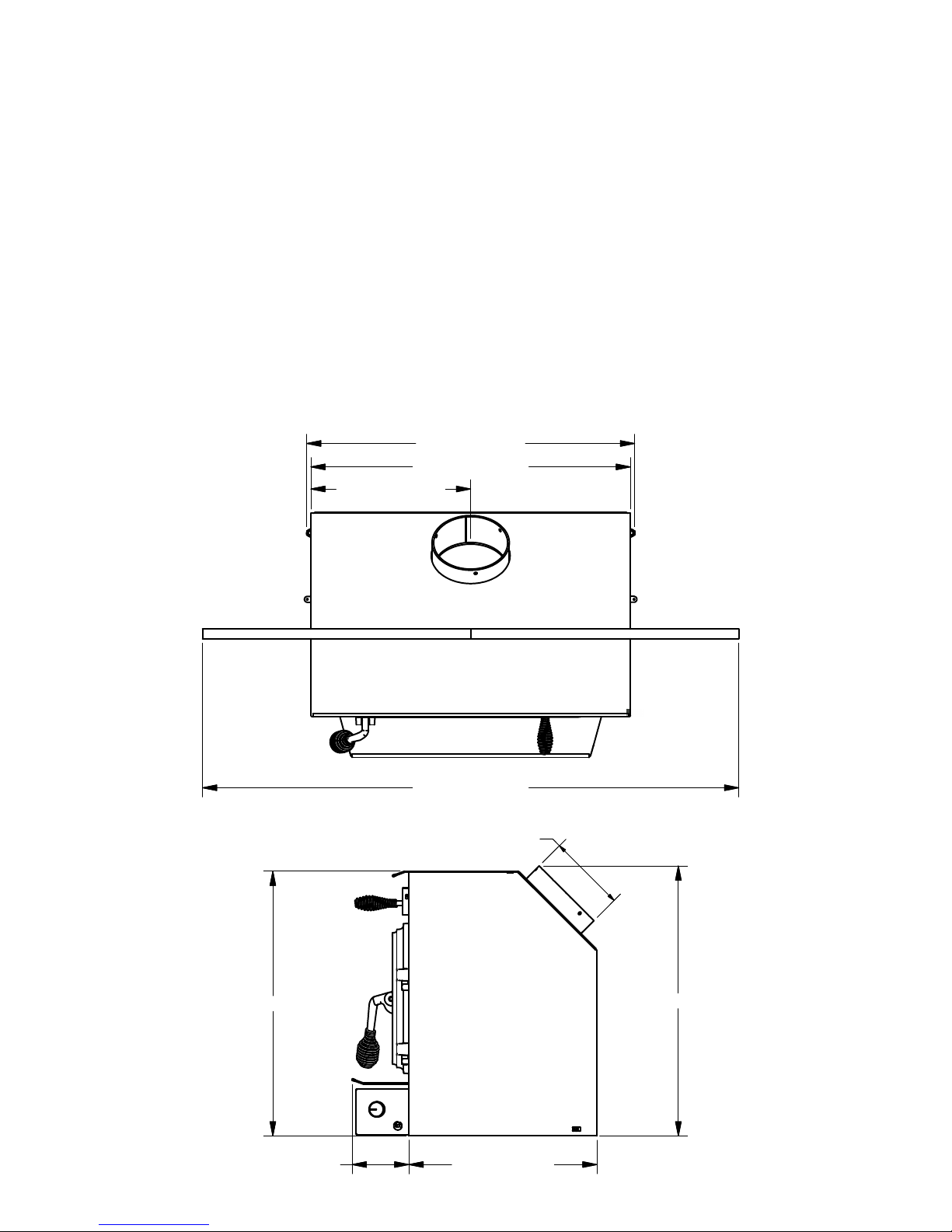
Dimensions
27 1/32 [686.6 mm]
26 11/32 [669.0 mm]
13 5/32 [334.5 mm]
26. U.S. Stove Company requires installing smoke
detectors in the same room as the heater if not
already installed. Smoke expelled from the unit by
either paint curing, opening the fuel loading door,
or a negative pressure inside the home could
trigger the smoke detectors.
27. For further information on using your heater safely,
obtain a copy of the National Fire Protection
Association (NFPA) publication “Using Coal and
Wood Stoves Safely” NFPA No. HS-10-1978. The
address of the NFPA is 1 Battery March Park,
Quincy, MA. 02269.
21 13/16 [554.0 mm]
44 7/32 [1123.0 mm]
6.00 INSIDE
22 1/4 [565.0 mm]
15 1/2 [394.0 mm]4 11/16 [118.8 mm]
3
Pre-Installation Requirements
FIREPLACE CONDITION AND ZERO CLEARANCE REQUIREMENTS
A masonry replace must meet minimum code requirements, National Fire Protection Association, (NFPA) 211,
or the equivalent for a safe installation. Contact a professional, licensed installer, your local building inspector or
the local re authority for the requirements in your area. Your insurance company should be able to recommend
a qualied inspector.
Inspections should include the following:
1. Condition of the replace and chimney. A masonry replace and chimney MUST be inspected prior to
installation of this appliance. They must be free from cracks, loose mortar, creosote deposits, blockage or
other evidence of deterioration. If found, these items MUST be repaired prior to installation. DO NOT REMOVE
BRICKS or MORTAR from existing replace when installing this unit.
2. Chimney Size. Minimum chimney size is 6˝ (152mm) diameter. Maintain a 15 ft. minimum overall chimney
height measured from the top of appliance to the top of the chimney. Chimneys must extend at least 3 ft.
above the roof and at least 2 ft. above the highest point within 10 ft. of the chimney top. See the Chimney
Connections section of this manual.
3. Zero Clearance or Metal Heatform Fireplaces. These replaces and chimneys must meet the minimum code
specications as noted above. Factory built zero clearance replaces must be listed and suitable for solid fuel
use. Chimneys must be at least 7 inch diameter to accommodate a required, continuous, stainless steel liner
from the appliance’s ue collar to the top termination of the chimney. Only detachable parts that can be
easily replaced (i.e. damper parts, screens, doors and side, and back refractory panels) are to be removed.
These parts must be stored and readily available for replacement if the appliance is ever removed. The
removal of any parts that render the replace unusable for burning solid fuel requires a permanent label to
be afxed by the installer that states the replace is unsuitable for burning solid fuel unless the missing parts
are replaced and the replace is restored to its original, certied condition.
4. Chimney Caps. Mesh type chimney caps and spark arrestors must be able to be removed for regular
inspection and cleaning. Otherwise the mesh should be removed to prevent possible plugging. Check your
local re and building codes.
5. Chimney Liner. The chimney must be suitable for burning solid fuel. Install a continuous stainless steel liner
from the ue collar of the appliance to the top of the chimney. Liner must be UL Listed to UL1777.
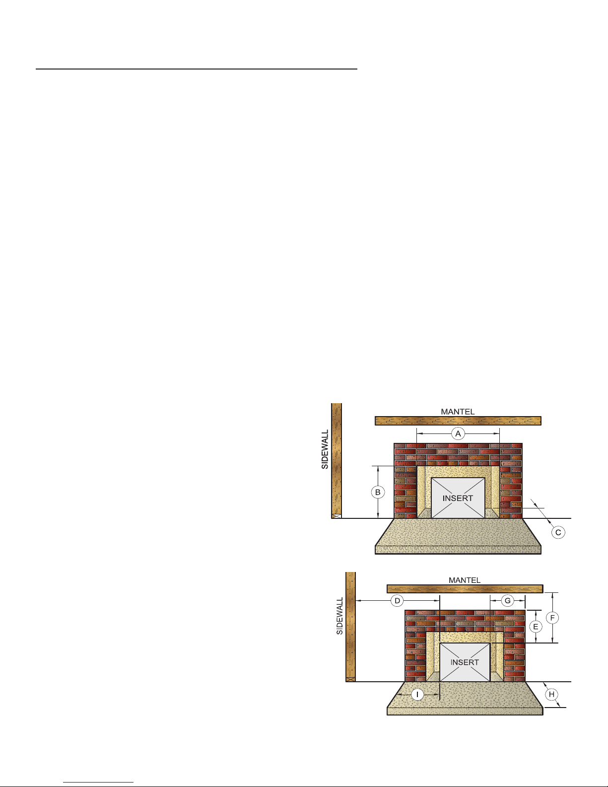
6. Fireplace Opening Dimensions.
A. Minimum Width 29˝ [737mm]
B. Minimum Height 23˝ [584mm]
C. Minimum Depth 14˝ [356mm]
7. Combustible Material Clearances. The replace and
chimney must be inspected to make sure there is
adequate clearance to combustible materials. This
includes the top, side, front, and back as well as
concealed combustibles in the chimney and mantle
areas. Your local building inspector or re authority
should have information on whether older replace
meet current codes and are suitable for use. See also
gure 1 and gure 2.
D. Min. Distance to Sidewall 9˝ [228mm]
E. Min. Distance to Top Trim 14˝ [355mm]
F. Min. Distance to Mantle 19˝ [482mm]
G. Min. Distance to Side Trim 9˝ [228mm]
H. Min. Floor Protector Front 12˝ [304mm]
I. Min. Floor Protector Side 6˝ [152mm]
Min. Floor Protector Side Canada ....8” [203]
8. Makeup Air Requirements. This appliance requires
an adequate supply of makeup air to operate safely
and efciently. In some areas, this is a building code
requirement. Inadequate air supply will cause poor
combustion, inefcient operation, creosote buildup,
back drafting and smoke pufng into the living areas. If
any of the following conditions are evident, a makeup
air supply MUST be installed.
4
a. Existing fuel-red equipment shows evidence of back pufng, smoke roll-out, inefcient operation, or
FLOOR PROTECTOR
Minimum Floor Protector Specificaons
excessive smell in the living area.
b. Opening a window or door alleviates any of the above problems or symptoms.
c. The building is constructed with a well-sealed vapor barrier, tight tting windows, or has powered exhaust
fans.
d. Excessive condensation on windows in the winter.
e. The building has a ventilation system installed.
f. If, once installed, the solid-fuel appliance does not draw steadily, burns poorly or inefciently, back-drafts or
experiences back-pufng when adding fuel.
VENTING (DRAFT) REQUIREMENTS
The chimney ue is a critical component to the proper and efcient operation of any heating appliance. Heating
appliances do not create draft, draft is provided by the chimney. This appliance requires a draft of 0.05 in. water
column (0.1 Pa) at the ue collar.
WARNING: RISK OF FIRE - EXCESSIVE DRAFT CAN CAUSE OVERFIRING AND A POSSIBLE STRUCTURE FIRE. DO NOT
OPERATE THIS APPLIANCE WITH THE FLUE DRAFT EXCEEDING 0.06 in. w.c. (0.1 Pa).
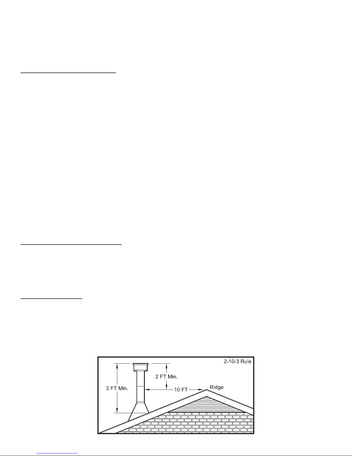
To achieve proper draft, your chimney must meet three minimum height requirements; minimum height from
top of appliance (15 ft. total height from top of appliance), minimum height above roof penetration (3 ft.), and
minimum height (2 ft.) above highest point of roof within a 10 ft. diameter from the chimney. The chimney must
also meet minimum and maximum cross sectional requirements. For that reason a continuous 6˝ stainless steel liner
from the ue collar to the top of the chimney is required. A stainless steel adapter is recommended for fastening
the stainless steel liner to the ue collar. The male (or crimped) end of the adapter must be installed inside the ue
collar to allow condensation or creosote in the liner to drain back into the rebox. Chimney liners and/or adapters
must be permanently fastened using a minimum of three (3) screws at each connection. Chimneys outside of the
home or on an exterior wall are difcult to keep at operating temperatures and may result in increased creosote
buildup, less draft, back drafting problems and poor appliance performance and should be avoided.
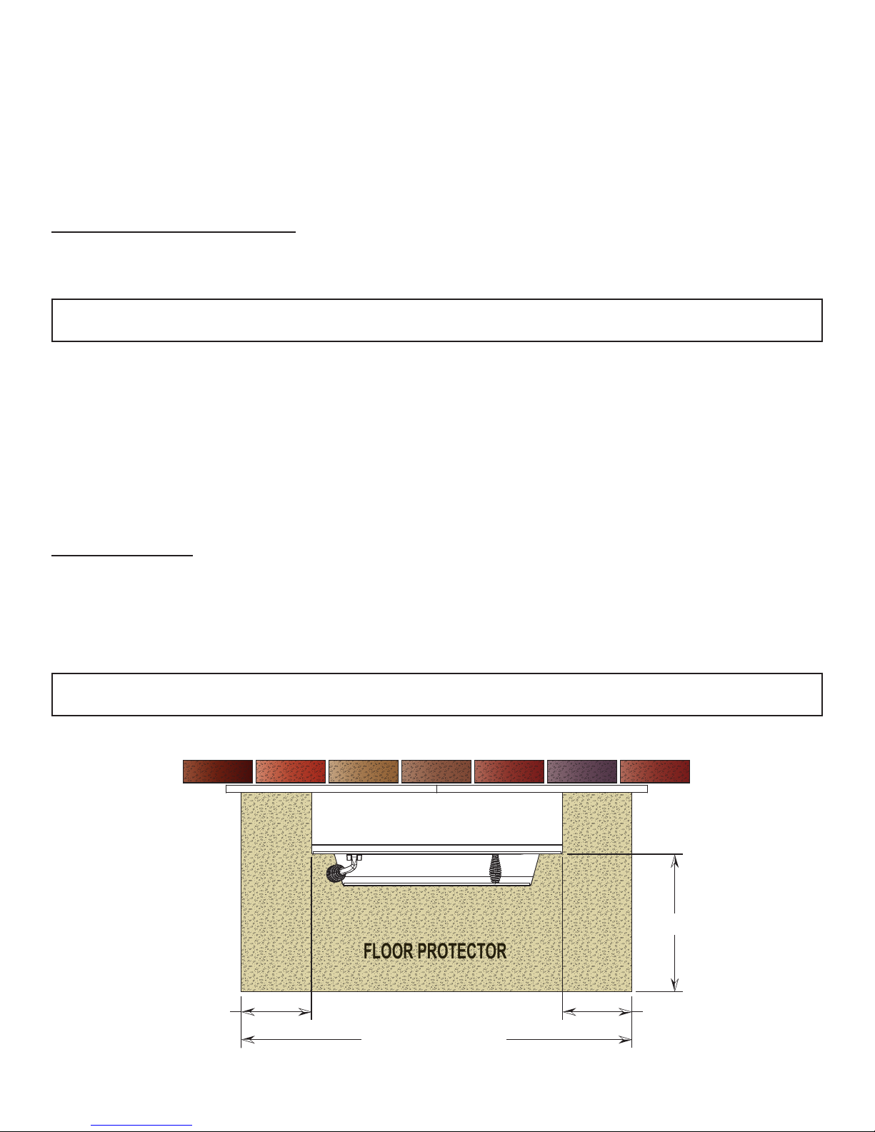
FLOOR PROTECTOR
A solid non-combustible oor, concrete or solid masonry, must extend 6˝ to either side of the body of the
appliance and 12˝ in front of the face of the appliance. When combustible ooring falls within these minimum
dimensions, it must be covered with a listed oor protector meeting the requirements of UL 1618, such as Hy-C
or Imperial Model UL 2840BK or equivalent with 0.84 R-factor, 1” thick. (Note: to calculate R-value of alternative
materials see Floor Protector Material Calculations at the back of this manual.) A grouted ceramic oor tile that
meets local building codes and the minimum 0.84 R-factor requirements is considered a durable equivalent.
WARNING: RIsk of re - do not allow combustible materials (carpet, furniture, fuels) to be placed on or cover
the oor protector. All combustible materials must remain outside of the minimum clearance dimensions.
12 inches [305mm]
US - 6 in. [152mm]
CAN - 8 in. [203mm]
US - 6 in. [152mm]
CAN - 8 in. [203mm]
US - 38 inches [965mm]
CAN - 42 inches [1.06M]
5
Assembly Instructions
TOOLS AND MATERIALS REQUIRED FOR INSTALLATION
(NOTE: The following items are NOT included with your stove.)
• Pencil
• 6 foot Folding Ruler or Measuring Tape
• Tin Snips
• Drill: Hand or Electric
• 1/8” dia. Drill Bit (for sheet metal screws)
• Screwdrivers (Blade and Phillips type)
• 14mm Nut Driver or Ratchet with 14mm Socket
• Flooring Protection: as specied herein.
CAUTION: this appliance is heavy. Make sure that you have adequate help and use proper lifting techniques
whenever moving this appliance.
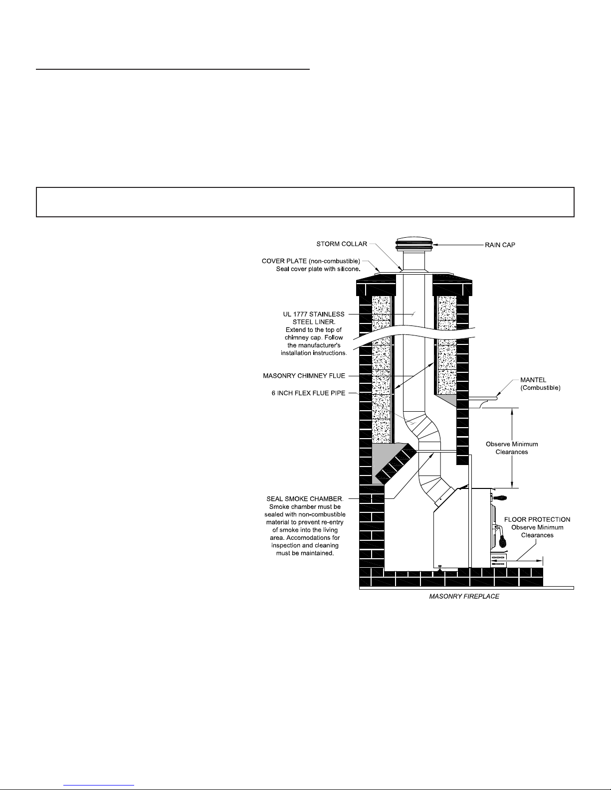
1. Clean the replace opening properly
disposing of any ashes in a closed metal
container. See Safety Instructions.
2. Install a 6˝ (152mm) minimum diameter,
continuous stainless steel chimney liner
into the existing chimney. The liner
must extend to the top of the existing
chimney. Use only listed chimney
liners that meet UL1777 standards.
Follow liner manufacturer installation
instructions.
3. Remove or lock the replace damper
in the open position. Note: Masonry
or damper plate may be removed
to accommodate the chimney liner
provided this does not weaken any
structural components of the existing
replace or chimney nor reduces
protection of combustible materials
required by national building codes.
Consult with your local building or re
authority before doing this.
4. Uncrate the appliance, remove all
packing materials, and any items
stored in the rebox.
5. WARNING: Any replace which has
had parts removed or modied to
accommodate the installation of
this appliance MUST have a warning
plate permanently installed in a visible
location stating that the replace is
unt for use with solid fuel. Permanently
attach the warning plate to a visible
location in the replace.
6. Position the appliance into the replace opening until the top lip of the air jacket is ush with the replace
facing.
7. Level the appliance with the adjusting screws at the rear of the appliance.
8. Connect the chimney liner to the appliance using a stainless steel adapter and securing with a minimum
of three (3) sheet metal screws. The liner MUST be attached with the male (or crimped) end of the adapter
inside the ue collar of the appliance to allow condensation and/or creosote to drain back into the rebox.
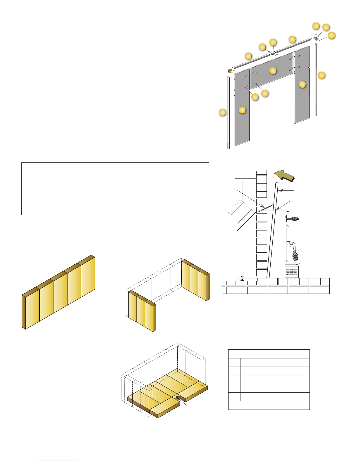
9. Assemble the Surround. Lay pieces face down on carpet or other soft surface to protect nish during
assembly. The Surround consists of two side panels, a top panel, and a decorative trim frame.
10. Bolt the top panel (1) to the side panels (2 and 14) so the top surfaces are ush to one another using items
3 and 4.
• Chimney Liner: Continuous stainless steel chimney
liner (as required)
• Stainless Steel Adapter (connects the liner to the
ue collar)
• 1/2” Sheet Metal Screws
• Furnace Cement (manufacturer recommends
Rutland Code 78 or equivalent)
• Fire Place Insert Surround Kit (TK004)
6
11. Assemble the trim frame. The trim consists of a left (6) and right
A
A
A
A
A
B
B
B
B
B
B
(5) side piece and a split top piece (left #8, right #7). These
are joined by corner connectors (11-13) and two straight center
connectors (9-10). These slide into the channel on the back of
the frame and are secured with two set screws (13) in each
piece.
12. The trim slides over the surround assembly and is secured at the
base of each side with a machine screw.
13. The Surround Assembly is then slid over the appliance. Slots in
the two side panels accommodate the hood at the top of the
appliance (gure 6).
14. The surround assembly is held in place with two springs at the
top of either corner of the appliance (gure 6).
15. Connect power cord of blower to grounded receptacle.
16. Firebrick extends the life of your stove and radiates heat more
evenly. If rebricks were removed to position appliance, replace
them before ring appliance. See gure 7 for proper orientation
and positioning. Install the back row rst, then sides and nally
install bottom rebricks.
11
12
10
9
7
1
4
3
5
14
SURROUND ASSEMBLY
VIEW FROM BACK
8
2
13
6
• Replace rebricks before ring woodstove. Position rebricks
so no gaps remain between bricks.
• Never operate this appliance with missing or cracked
rebrick.
• Keep furnishings and other combustible materials away from
the stove and outside minimum clearances.
Figure 7a -
Back Firebrick Arrangement
Five (5) A-Size
A
A
A
CAUTION: RISK OF FIRE!
A
A
Figure 7b -
Side Firebrick Arrangement
Six (6) B-Size
B
B
B
B
B
B
SPRING
Figure 6. Surround Installation
SURROUND
Slots in surround
slide of rebox top
Figure 7c -
Bottom Firebrick Arrangement
Four (4) A-Size
Two (2) C-Size
One (1) D-Size
One (1) E-Size
A
A
D
C
A
A
C
E
Firebrick Dimensions: (inches)
A 4.50” x 9.00”
B 3.33” x 9.00”
C 3.38” x 9.00”
D 2.25” x 9.00”
E 1.25” x 2.25”
Note: All Firebrick is 1.25” Thick
7
Chimney Specications
This appliance must be connected to a listed Stainless Steel Liner, that meets UL1777, which extends from the
collar to the chimney cap according to the specications listed on the previous pages. Take into account the
chimney’s location to insure it is not too close to neighbors or in a valley which may cause unhealthy or nuisance
conditions.
IMPORTANCE OF PROPER DRAFT
Draft is the force which moves air from the appliance up through the chimney. The amount of draft in your
chimney depends on the length of the chimney, local geography, nearby obstructions and other factors. Too
much draft may cause excessive temperatures in the appliance. Inadequate draft may cause backpufng into
the room and ‘plugging’ of the chimney. Inadequate draft will cause the appliance to leak smoke into the room
through appliance and chimney connector joints. An uncontrollable burn or excessive temperature indicates
excessive draft.
Chimneys perform two functions:
1. As a means of exhausting smoke and ue gases which are the result of fuel combustion.
2. The chimney provides “draft,” which allows oxygen to be continuously introduced into the appliance, so
that proper combustion is possible. This stove relies on natural draft to operate.
NOTICE: Always provide a source of fresh air into the room where the stove is located. Failure to do so may result
in air starvation of other fuel burning appliances and the possible development of hazardous conditions, re, or
death.
Your appliance itself does not create draft. Draft is provided by the chimney. To achieve proper draft your
chimney must meet the three minimum height requirements detailed in gure 8. A minimum draft of 0.05 w.c.
(measured in water column) is required for proper drafting to prevent back pufng, smoke spillage, and to
maximize performance. (Gauges to measure draft are readily available at stove stores and are economical to
rent or purchase.)
Factors such as wind, barometric pressure, trees, terrain and chimney temperature can have an adverse effect
on the draft. The manufacturer cannot be held responsible for external factors leading to less than optimal
drafting.
Should you have a problem with inadequate draft, you should contact a licensed heating and cooling contractor
for assistance in solving the problem.
IMPORTANT INSTALLATION POINTS
1. Size chimney ue to appliance collar. This stove requires a minimum 6” diameter ue.
2. Never connect this unit to a chimney serving another appliance.
3. The chimney must meet all minimum height requirements.
4. Never use a chimney to ventilate a cellar or basement.
Contact your local building authority for approved methods of installation and any necessary permits and/or
inspections.
MASONRY CHIMNEY
Before using an existing masonry chimney, clean the chimney, inspect the ue liner, and make any repairs
needed to be sure it is safe to use. As mentioned previously, this appliance requires a continuous stainless steel
liner from the appliance collar to the chimney cap. Make repairs before attaching the stove. The connector
stove pipe and ttings you will need to connect directly to a masonry chimney are detailed in the installation
instructions. If the replace chimney must go through a combustible wall before entering the main chimney,
consult a qualied mason or chimney dealer regarding proper materials that meet all local building and re
authority codes. The installation must conform to local building and re codes and latest edition of NFPA 211. If
there is a cleanout opening in the base of the chimney, close it tightly.
8
Fuel Recommendations
WOODSTOVE UTILIZATION
Your heating appliance was designed to burn wood only; no other materials should be burned. Waste and
other ammable materials should not be burned in your stove. Any type of wood may be used in your stove, but
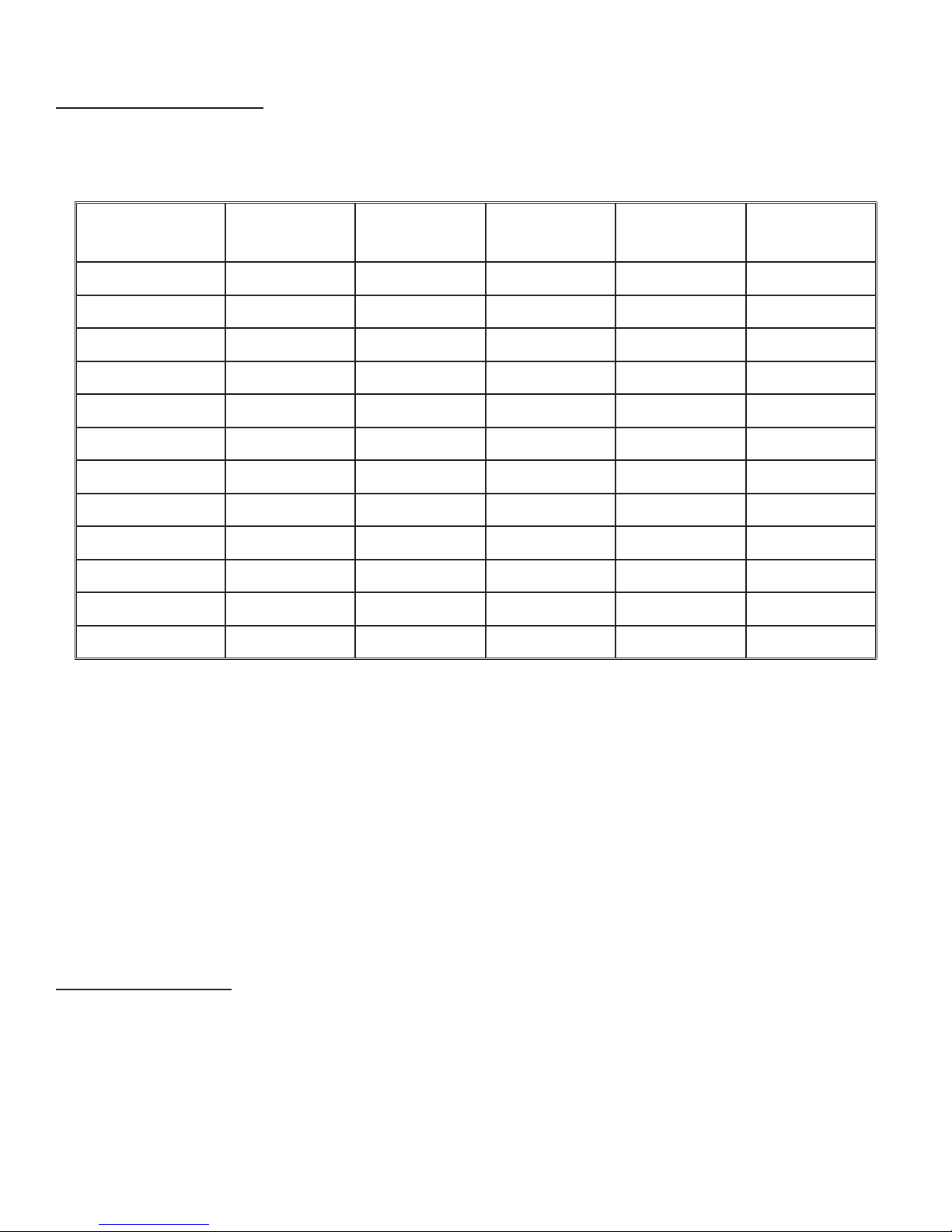
specic varieties have better energy yields than others. Please consult the following table in order to make the
best possible choice.
WEIGHT
TYPE
Hickory 63 4500 1.0 Well 31.5
White Oak 48 4100 .9 Fair 28.6
Red Oak 46 3900 .8 Fair 27.4
Beech 45 3800 .7 Hard 26.8
Sugar Maple 44 3700 .6 Fair 26.2
Black Oak 43 3700 .6 Fair 25.6
Ash 42 3600 .5 Well 25.0
Yellow Birch 40 3400 .4 Hard 23.8
Red Maple 38 3200 .3 Fair 22.6
Paper Birch 37 3100 .3 Easy 22.1
Elm/Sycamore 34 2900 .2 Very Difcult 20.1
Red Spruce 29 1800 .1 Easy 16.1
(LBS. CU. FT.,
DRY)
PER CORD
EFFICIENCY
RANKING
SPLITS
MILLIONS BTU’s/
CORD
It is EXTREMELY IMPORTANT that you use DRY WOOD only in your wood stove. The wood should have dried for
9 to 15 months, such that the humidity content (in weight) is reduced below 20% of the weight of the log. It is
very important to keep in mind that even if the wood has been cut for one, two, or even more years, it is not
necessarily dry, if it has been stored in poor conditions. Under extreme conditions it may rot instead of drying.
This point cannot be over stressed; the vast majority of the problems related to the operation of a wood stove is
caused by the fact that the wood used was too damp or had dried in poor conditions. These problems can be:
- ignition problems
- creosote build-up causing chimney res
- low energy yield
- blackened windows
- incomplete log combustion
Smaller pieces of wood will dry faster. All logs exceeding 6” in diameter should be split. The wood should not be
stored directly on the ground. Air should circulate through the cord. A 24” to 48” air space should be left between
each row of logs, which should be placed in the sunniest location possible. The upper layer of wood should be
protected from the element but not the sides.
TESTING YOUR WOOD
When the stove is thoroughly warmed, place one piece of split wood (about ve inches in diameter) parallel to
the door on the bed of red embers.
Keep the air control full open and close the door. If ignition of the piece is accomplished within 90 seconds from
the time it was placed in the stove, your wood is correctly dried. If ignition takes longer, your wood is damp.
If your wood hisses and water or vapor escapes at the ends of the piece, your wood is soaked or freshly cut
(green). Do not use this wood in your stove. Large amounts of creosote could be deposited in your chimney,
creating potential conditions for a chimney re.
9

Operating Instructions
CAUTIONS: HOUSE FIRE HAZARDS
• Do not store wood on oor protector, underneath stovepipe(s) if applicable, or anywhere within
clearances to combustible surfaces specied for this appliance.
• Never operate with secondary tubes, ber board, or insulation removed.
OPERATING SAFETY PRECAUTIONS
• Never overre this appliance by building excessively hot res as a house/building re may result. You are
overring the appliance if it begins to glow or turn red.
• Never build excessively large res in this type of appliance as damage to the rebox or smoke leakage
may result.
• Do not build re too close to glass.
• Hot while in operation. Keep children, clothing, and furniture away. Contact may cause skins burns. Do not
touch the appliance until it has cooled.
• Provide adequate air for combustion to the room where the appliance is installed.
• Inspect chimney liner every 60 days. Replace liner immediately if it is rusting or leaking smoke into the
room.
• Attempts to achieve heat output rates that exceed heater design specications can result in permanent
damage to the heater.
WARNING: EXPLOSION HAZARD
• Never use chemicals, gasoline, gasoline-type lantern fuel, kerosene, charcoal lighter uid, or similar
ammable liquids to start or “freshen up” a re in the appliance.
• Keep all ammable liquids, especially gasoline, out of the vicinity of the appliance - whether in use or in
storage.
THIS APPLIANCE IS DESIGNED TO BURN NATURAL WOOD FUEL ONLY!
Hardwood, 17” to 19”, should be split and air dried (seasoned) for 6 months to obtain maximum burning efciency.
Wood should be stored in a dry, well ventilated area.
Burning fuels other than intended, chemicals, or waste in this appliance could result in damages to the heater
or result in bodily injury. It will also void any warranty on the appliance.
This heater is designed to burn natural wood only. Higher efciencies and lower emissions generally result when
burning air dried seasoned hardwoods, as compared to softwoods or to green or freshly cut hardwoods.
DO NOT BURN:
1. Garbage;
2. Lawn clippings or yard waste;
3. Materials containing rubber, including tires;
4. Materials containing plastic;
5. Waste petroleum products, paints or paint thinners, or asphalt products;
6. Materials containing asbestos;
7. Construction or demolition debris;
8. Railroad ties or pressure-treated wood;
9. Manure or animal remains;
10. Salt water driftwood or other previously salt water saturated materials;
11. Unseasoned wood; or
12. Paper products, cardboard, plywood, or particleboard. The prohibition against burning these materials does
not prohibit the use of re starters made from paper, cardboard, saw dust, wax and similar substances for the
purpose of starting a re in an affected wood heater.
Burning these materials may result in release of toxic fumes or render the heater ineffective and cause smoke.
Dead wood lying on the forest oor should be considered wet, and requires full seasoning time. Standing dead
wood can usually be considered to be about 2/3 seasoned. Splitting and stacking wood before it is stored
accelerates drying time. Storing wood on an elevated surface from the ground and under a cover or covered
area from rain or snow also accelerates drying time. A good indicator if wood is ready to burn is to check the
piece ends. If there are cracks radiating in all directions from the center then the wood should be dry enough
to burn. If your wood sizzles in the re, even though the surface is dry, it may not be fully cured, and should be
seasoned longer.
10

Do not burn manufactured logs made of wax impregnated sawdust or logs with any
chemical additives. Manufactured logs made of 100% compressed sawdust can be
burned, but be careful burning too much of these logs at the same time. Start with one
manufactured log and see how the stove reacts. You can increase the number of logs
burned at a time to making sure the temperature never rises higher than 475 °F (246 °C)
on a magnetic thermometer for installation on single wall stove pipes or 900 °F (482 °C)
on a probe thermometer for installation on double wall stove pipe. The thermometer
should be placed about 18” (457 mm) above the stove. Higher temperatures can lead
to overheat and damage your stove.
OPTIMAL FUEL CONSUMPTION
This appliance is designed to get the most efcient transfer of heat energy from the wood fuel and radiate it into
your living environment. The re box introduces combustion air through three sources; (1) Immediately beneath
the door opening below the window is a Lower Primary Air Orice (LPAO), (2) The door air inlet control brings air
into the rebox and controls the rate of burn (and the amount of heat the appliance radiates), (3) The secondary
air tubes at the top of the rebox are designed to ignite the combustion gases (smoke) given off by the burning
wood and increases the efciency of the appliance and reduces chimney emissions.
Smoke given off by burning fuel consists of very small organic liquid droplets. If these droplets condense, they
form a sticky tar-like substance called creosote. When operated properly, this appliance is designed to burn these
droplets. Burning these droplets releases heat that would otherwise be lost up the chimney as smoke. Following
the instructions below will help you operate your appliance properly to maximize the appliance’s performance.
Actual performance is dependent on chimney height, weather, log size, wood species, and moisture content.
Some experimentation will initially be required to nd that spot where your appliance performs best. The following
will give you a starting point to nd your optimum settings.
When rst loading fuel, set the door air inlet control at the wide open position for at least 15–20 minutes. When
the appliance is working properly, you should be able to observe secondary combustion ames above the fuel
pieces in front of the secondary air tubes at the top of the rebox. These secondary ames should continue
to burn after the primary air inlet is reset from wide open to the desired operating setting. If the ames do not
continue to burn, open the air control to re-establish the secondary ames then slowly reset the air control to the
desired setting. Initially it may take several attempts to gure your appliance out. But once you nd the efcient
operating spot and the correct mix of procedures to get there, only minor adjustments will be necessary.
The best indicator of a properly operating appliance is to look for smoke coming out of the chimney. You may
see steam emissions that will quickly dissipate. Smoke will thin but continue to drift without totally disappearing.
If you do detect smoke emissions, open the air control a little bit, let the appliance adjust for 10–15 minutes and
re-check your chimney. Remember – visible smoke represents lost heat.
Notice: Use solid wood fuel only! Do not burn garbage , or ammable uids. Do not use coal. This appliance
is not designed to accommodate the air ow (draft) required to properly burn coal or coal products. Do not
elevate the re using grates or irons. Build the re directly on the rebrick.
TAMPER WARNING
This wood heater has a manufacturer-set minimum low burn rate that must not be altered. It is against federal
regulations to alter this setting or otherwise operate this wood heater in a manner inconsistent with operating
instructions in this manual.
EFFICIENCIES
Efciencies can be based on either the lower heating value (LHV) or the higher heating value (HHV) of the fuel.
The lower heating value is when water leaves the combustion process as a vapor, in the case of woodstoves the
moisture in the wood being burned leaves the stove as a vapor. The higher heating value is when water leaves
the combustion process completely condensed. In the case of woodstoves this would assume the exhaust gases
are room temperature when leaving the system, and therefore calculations using this heating value consider
the heat going up the chimney as lost energy. Therefore, efciency calculated using the lower heating value of
wood will be higher than efciency calculated using the higher heating value. In the United States all woodstove
efciencies should be calculated using the higher heating value.
The best way to achieve optimum efciencies is to learn the burn characteristic of you appliance and burn wellseasoned wood. Higher burn rates are not always the best heating burn rates; after a good re is established a
lower burn rate may be a better option for efcient heating. A lower burn rate slows the ow of usable heat out
of the home through the chimney, and it also consumes less wood.
11

NOTICE - INITIAL BURNS TO CURE PAINT
BECAUSE OF THE HIGH OPERATING TEMPERATURES, THIS APPLIANCE IS COATED WITH A SPECIAL HIGH TEMP PAINT
WHICH REQUIRES A SERIES OF LOW TO MEDIUM BURNS TO FULLY CURE FOR DURABILITY AND A LIFETIME OF SERVICE.
Proper curing of the high-temp paint requires a series of three initial burns. The appliance should be allowed to
cool off between each burn. The rst two burns should be small res and low temperatures (250 degrees F) for
a duration of 20 minutes each. The third re should be at a temperature of approximately 500 F for 20 minutes.
Provide adequate cross ventilation to clear any smoke or odor caused by initial rings.
STARTING A FIRE
DO NOT LEAVE APPLIANCE UNATTENDED WITH DOOR OPEN! The top down method of re building is recommended
for this appliance. After making sure that the stove air intake controls are fully open (completely pull-out towards
you), Place the largest pieces of wood on the bottom, laid in parallel and close together. Smaller pieces are
placed in a second layer, crossways to the rst. A third layer of still smaller pieces is laid crossways to the second,
this time with some spaces between. Then a fourth layer of loose, small kindling and twisted newspaper sheets
tops off the pile. Add large pieces of wood as the re progresses being careful not to overload. (Do not ll rebox
beyond rebrick area.) An ideal ember bed of 1 – 2” should be established to achieve optimum performance.
This unit is designed to function most effectively when air is allowed to circulate to all areas of the rebox. TIP: If
ash or embers remain in the appliance, make sure to clear them away from the Lower Primary Air Orice (LPAO)
and rake a slight (1-to-2 inch wide) trough down the center of the embers from front to back prior to loading
the fuel. Once fuel has been loaded, close the door and leave the air inlet control fully open until re is well
established (at least 15–20 minutes) being careful not to over re (if any of the exterior parts of the appliance
or chimney connections begin to glow you are over ring the appliance). Re-adjust the door air inlet control to
desired burn rate. (If excessive smoke lls the rebox, open air inlet control slightly until ames resume and wood
is sufciently ignited.) The basic rule of thumb is “closed - low,” “half way open - medium” and “fully open - high.”
The amount of visible smoke being produced can be an effective method of determining how efciently the
combustion process is taking place at the given settings. Visible smoke consist of unburned fuel and moisture
leaving your stove. Learn to adjust the air settings of your specic unit to produce the smallest amount of visible
smoke. Wood that has not been seasoned properly and has a high wood moisture content will produce excess
visible smoke and burn poorly.
ADDING FUEL
If the embers are not hot and glowing, rake the embers to the front of the appliance, close the door and adjust
the air inlet control to the wide open position. Let the embers re-heat for 10–15 minutes. When hot and glowing,
spread them out and place your next fuel load into the appliance (make sure no embers or ashes block the
LPAO). Leave the door air inlet control in the wide open position for 15–20 minutes.
Fuel load size can vary but should be kept 1–2 inches below the secondary air tubes. Also position the fuel to
leave space so the air from the inlet can work down between the pieces of fuel. This reduces the time it takes for
new fuel to burn properly.
1. When refueling, adjust air inlet control to the fully open position. When re brightens, slowly and carefully
open the door. This procedure will prevent gases from igniting causing smoke and ame spillage.
2. Add fuel being careful not to overload or overre the appliance.
3. When adding fuel be careful not to smother the re. Do not build res against glass and make sure the
embers do not obstruct the air inlet. Do not allow logs to roll and strike the glass.
4. Close the feed door and secure tightly.
5. Adjust the air inlet control as described above.
6. Empty ashes regularly. Do not allow ashes to pile up.
7. Properly dispose of hot ashes.
8. Do not overre the appliance (overring is when any part of the appliance’s exterior or chimney connections
glow).
OPERATIONAL TIPS
• Get the appliance hot and establish a good coal bed before adjusting to a low burn rate (this may take 30
minutes or more depending on your wood)
• Use smaller pieces of wood during start-up and a high burn rate to increase the stove temperature
• Be considerate of the environment and only burn dry wood
• Burn small, intense res instead of large, slow burning res when possible
• Learn your appliance’s operating characteristics to obtain optimum performance
• Burning unseasoned wet wood only hurts your stoves efciency and leads to accelerated creosote buildup
in your chimney
12
 Loading...