

Vogelzang International PONDEROSA TR007 Owner's Manual
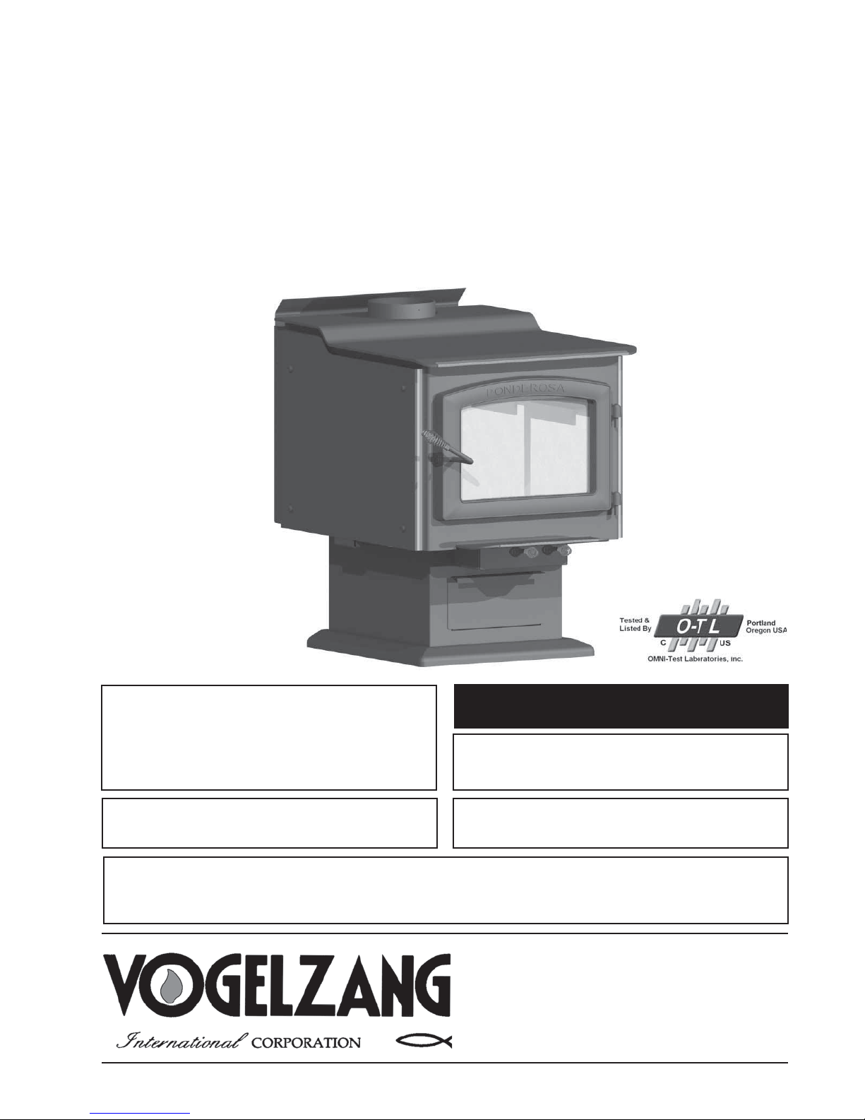
PONDEROSA
HIGH-EFFICIENCY WOODSTOVE
EPA Certified (3.20 grams/hr.)
Model TR007 Owners Manual
(Save These Instructions)
Le manuel de langue français est disponible à www.vogelzang.com
French language manual is available at www.vogelzang.com
™
Report No. 180-S-09-2
READ ALL INSTRUCTIONS CAREFULLY
BEFORE INSTALLING OR OPERATING
THIS STOVE. FAILURE TO FOLLOW INSTRUC-
TIONS MAY RESULT IN PROPERTY DAMAGE,
BODILY INJURY, OR EVEN DEATH.
REFER TO MARKINGS ON STOVE LABELS FOR
ADDITIONAL INFORMATION.
SAFETY NOTICE: IF THIS STOVE IS NOT PROPERLY INSTALLED, A HOUSE/BUILDING FIRE MAY
RESULT. FOR YOUR SAFETY, CONTACT LOCAL OR MUNICIPAL BUILDING OR FIRE OFFICIALS
ABOUT PERMITS, RESTRICTIONS, AND INSTALLATION REQUIREMENTS FOR YOUR AREA.
VGZ-031 / 20120619.1 www.vogelzang.com TR007 PONDEROSA™ / Page 1
US: UL 1482-2011 & CDN: ULC-S627-00
NOTE: IT IS RECOMMENDED INSTALLATION
BE COMPLETED BY A QUALIFIED HEATING
ROOM HEATER, SOLID FUEL TYPE, ALSO
FOR USE IN MOBILE HOMES (USA ONLY).
This stove meets test standards:
EQUIPMENT INSTALLER!
Vogelzang International Corporation
400 West 17th Street
Holland, Michigan 49423
www.vogelzang.com
Phone: 1-616-396-1911
Fax: 1-616-396-1971

SAFETY INSTRUCTIONS-Read All Instructions Carefully.
1. The installation of this stove must comply with your
local building code rulings. Please observe the clearances to combustibles (see reference figures 5–7).
Do not place fuel, furniture or any other objects within
the clearance area.
2. Verify that the stove is properly assembled and
installed before firing the stove for the first time.
After reading these instructions, if you have any
doubt about your ability to complete your installation
properly, you must obtain the services of a
professional licensed installer familiar with all
aspects of safe and correct installation. DO NOT
use temporary or makeshift compromises
during installation. There must be NO DEVIATION
OR ALTERATION OF ANY KIND from the very specific instructions spelled out in this instruction manual
as it pertains to the installation of this woodstove.
NO EXCEPTIONS!
3. DO NOT store wood, kindling, flammable liquids
or other combustible materials in the vicinity of the
appliance. Refer to certification label on back of unit
and reference figures 5–7 in this manual.
4. FOR MOBILE HOME INSTALLATIONS IN U.S.A.
ONLY. DO NOT INSTALL IN MOBILE HOMES IN
CANADA. See additional mobile home requirements on page 10.
5. DO NOT ELEVATE THIS STOVE BY ANY MEANS.
(i.e. bricks under pedestal, cement blocks) Stove
pedestal must set directly upon the solid-surface noncombustible floor as specified in this stove instruction
manual.
6. DO NOT MODIFY THIS STOVE IN ANY WAY!
Stove must be installed with pedestal and ash drawer
provided, attached as shown in the instructions.
DO NOT OPERATE WITHOUT ASH DRAWER
OR ASH CLEAN OUT COVER IN PLACE – NO
EXCEPTIONS. Assemble only with original parts as
supplied and shown in this manual. DO NOT OPER-
ATE A STOVE THAT IS MISSING ANY PARTS! If
any parts are missing or defective, please notify
the dealer or manufacturer immediately. Replace
missing, broken or worn parts with factory original
or equivalent parts only.
7. CAUTION: DO NOT ALTER COMBUSTION AIR
CONTROL RANGE TO INCREASE FIRING OR
FOR ANY REASON. Altering or tampering with air
control beyond normal capacity will create unsafe
and hazardous conditions.
8. Always connect this stove to a chimney and vent to
the outside. Never vent to a room or inside a building.
DO NOT CONNECT THIS UNIT TO A CHIMNEY
FLUE SERVING ANOTHER APPLIANCE.
9. DO NOT CONNECT A WOOD BURNING STOVE
TO AN ALUMINUM TYPE B GAS VENT. This is
not safe. Use code-approved masonry chimney
with flue liner or a manufactured Underwriters
Laboratories Listed UL 103 HT (US)/ULC-S629
(CDN) Residential Type and Building Heating Appliance Chimney. Use a 6˝/152mm diameter chimney, that is high enough to give a good draft. (See
specifics in Chimney Connections instructions).
10. Be sure that your chimney is safely constructed and
in good repair. Have the chimney inspected by the fire
department or a qualified inspector. Your insurance
company should be able to recommend a qualified
inspector. Chimney connector pipe must be in good
condition. Replace if necessary before using stove.
11. Creosote or soot may build up in the chimney
connector and chimney and cause a house/building
fire. Inspect the chimney connector and chimney
twice monthly during the heating season and clean
if necessary. (see Service Hints).
12. In the event of a chimney fire, turn the air controls to
closed positions, leave the building and CALL THE
FIRE DEPARTMENT IMMEDIATELY! Have a clearly
understood plan on how to handle a chimney fire by
contacting your local fire authority for information
on proper procedures in the event of a chimney fire.
After the fire is out, the chimney must be cleaned
and inspected for any stress or cracks before starting
another fire. Check the condition of any combustibles
surrounding the chimney.
13. Ashes should not be allowed to accumulate above
the top of the lower primary air orifice (LPAO, air vent
at front of firebox, just inside of door).
14. DISPOSAL OF ASHES
Ashes should be placed in a steel container with
a tight fitting lid and moved outdoors immediately.
The closed container of ashes should be placed
on a noncombustible floor or on the ground, well
away from all combustible materials, pending final
disposal. If the ashes are disposed of by burial in
soil or otherwise locally dispersed, they should be
retained in the closed container until all cinders have
completely cooled. Other waste shall not be placed
in this container.
15. To prevent injury, do not allow anyone use this stove
who is unfamiliar with the correct operation.
16. Do not operate stove while under the influence of
drugs or alcohol.
17. DO NOT ELEVATE THE FIRE. Build fire directly on
the bottom of the firebox. This stove has not been
tested with the use of grates, andirons or other means
of elevating the fire and must not be used.
Page 2 / TR007 PONDEROSA™ Vogelzang International Corp. VGZ-031 / 20120619.1

SAFETY INSTRUCTIONS continued…
18. During the first 12 to 15 fires the special paints and protective oils used in construction of your stove may give
off some smoke and odor while they are curing. This
should disappear after a short period of time and not
occur again. Persons with lung conditions or owners of
susceptible domestic pets (such as birds) should take
prudent precautions. Open windows and doors as
needed to clear smoke and/or odor. Paint discoloration will occur if the stove is over fired.
19. This stove has a painted surface which is durable
but it will not stand rough handling or abuse. When
installing your stove, use care in handling.
20. CLEAN STOVE FREQUENTLY as soot, creosote
and ash may accumulate. Clean exterior with soap
and warm water when stove is not hot. Do not use
any acids or scouring soap, as these solvents wear
and dull the finish.
21. ALERT ALL PERSONS TO THE HAZARDS OF
HIGH SURFACE TEMPERATURES while stove is
in operation – especially young children. Keep away
from a hot stove to avoid burns or clothing ignition.
22. NEVER LEAVE SMALL CHILDREN UNSUPER-
VISED WHEN THEY ARE IN THE SAME ROOM
AS THE STOVE. If small children will be in the same
room as the stove during operation, provide a sturdy
barrier to keep them at a safe distance from the stove.
23. Keep stove area clear and free from all combustible
materials, gasoline, engine oil, naphtha and other
flammable vapors and liquids.
24. WHILE TENDING THE FIRE ALWAYS WEAR PRO-
TECTIVE CLOTHING, fire retardant hearth gloves
and eye protection, to prevent burns.
25. Never operate this stove without ash drawer, ash
clean out or with the door open except when refueling. Such actions can result in very dangerous
operating conditions.
26. DO NOT OVER FIRE THE STOVE. Over firing
will occur if combustion air is uncontrolled as when
feed door is left open during operation. Such actions
can result in very dangerous operating conditions.
While in operation, keep the feed door closed and
secured at all times except while tending the fire
27. When adding fuel be careful not to smother the fire.
Do not build fires against glass and do not load fuel to
a height or in such a manner that it creates a hazard
when opening the door.
28. NEVER LEAVE THE STOVE UNATTENDED with
door open. Always close the door after ignition.
29. DO NOT CONNECT TO OR USE IN CONJUNC-
TION WITH ANY AIR DISTRIBUTION DUCT WORK
UNLESS SPECIFICALLY APPROVED FOR SUCH
INSTALLATIONS.
30. A WOOD-BURNING STOVE MUST NEVER BE
INSTALLED IN A HALLWAY OR NEAR A STAIRCASE, as it may block egress in the event of a fire.
31. DO NOT INSTALL IN A SLEEPING ROOM.
DO NOT INSTALL IN AN ALCOVE OR INSIDE A
FIREPLACE.
32. Install at least one smoke detector on each floor of
your home. Detectors should be located away from
the heating appliance to avoid false alarms. Detectors
should be located close to sleeping areas. Follow
the smoke detectors manufacturer’s placement and
installation instructions. Maintain smoke detector per
manufacturer’s instructions.
33. CARBON MONOXIDE (CO) HAZARD. A buildup of
CO fumes is toxic and can be fatal. Carbon Monoxide
is a colorless, odorless gas produced during combustion of wood, coal, oil, gas and by other fuel burning
appliances. It is important to have a proper draft and
adequate replacement air ventilation so fumes are
drawn out the chimney. Installed as instructed this
stove is designed to be as safe as possible yet it is
recommended to install a CO detector. Follow the
manufacturer’s recommendations for proper installation and use. It is recommended to be placed at
table-top level (not near the ceiling) to avoid false
alarms. Realize that devices other than a stove (i.e.
motor exhaust) can trigger CO alarms.
If alarm sounds:
s 2ECOGNIZETHESYMPTOMSOF#/POISONINGHEAD-
aches, nausea & drowsiness).
s )NCREASEVENTILATIONOPENWINDOWSDOORS
s -AKESURESTOVEDOORSANDORLIDSARECLOSEDAND
secured.
s #HECK STOVEFORSMOKING ORPUFlNGOPENAIRmOW
controls).
s #HECKCHIMNEYCONNECTORPIPEFORLEAKSBLOCK-
age or down-draft conditions.
s #HECK#/DEVICEFORFALSEALARM
34. Keep power cords, electrical appliances and/or assemblies outside of the clearance area shown in this
manual for combustible materials.
35. Consult your municipal building department or fire
officials about restrictions, permits and installation
requirements for your area.
36. For further information on using your stove safely,
obtain a copy of the National Fire Protection
Association (NFPA) publication, “Using Coal and
Wood Stoves Safely” NFPA No. HS-10-1978. Write
NFPA, Batterymarch Park, Quincy, MA 02269.
VGZ-031 / 20120619.1 www.vogelzang.com TR007 PONDEROSA™ / Page 3

TABLE OF CONTENTS
SAFETY PRECAUTIONS ............................................................................... 2 – 3
TOOLS AND MATERIALS REQUIRED FOR INSTALLATION ............................ 5
ASSEMBLY INSTRUCTIONS .............................................................................. 5
LOCATING THE STOVE ...................................................................................... 7
Floor Protector, Minimum Clearances .............................................. 7 – 8
FIRE BRICK ASSEMBLY .................................................................................... 8
CHIMNEY SIZING ................................................................................................ 8
CONNECTOR PIPE INSTALLATION ................................................................... 9
MOBILE HOME INSTALLATION INSTRUCTIONS ............................................ 10
CHIMNEY CONNECTIONS/DRAFT ........................................................... 11 – 13
CHIMNEY CONNECTION SYSTEMS & CLEARANCES ................................... 14
OPERATING INSTRUCTIONS
House Fire Hazards, Operating Precautions, Warnings ...................... 15
Wood Types/Sizes .................................................................................... 15
Optimal Fuel Consumption .................................................................... 15
Starting a Fire ......................................................................................... 16
Adding Fuel ............................................................................................ 17
SERVICE HINTS
Creosote Formation, Prevention, Need for Removal .......................... 17
Chimney Draft ......................................................................................... 18
Glass Care & Replacement ................................................................... 19
Glass Gasket Replacement ................................................................... 20
OPTIONAL F-6 BLOWER MAINTENANCE & WIRING DIAGRAM ................... 21
PARTS – PONDEROSA™ ................................................................................. 22
PARTS – GLASS DOOR (Glass Replacement) ................................................ 23
PARTS – FIRE BRICK ........................................................................................ 23
FLOOR PROTECTOR CALCULATIONS ........................................................... 24
CHIMNEY & STOVE MAINTENANCE LOG ....................................................... 25
NOTE: A PROFESSIONAL, LICENSED HEATING AND COOLING CONTRACTOR MUST
BE CONSULTED IF YOU HAVE QUESTIONS
REGARDING THE INSTALLATION OF THIS
SOLID FUEL BURNING APPLIANCE.
Page 4 / TR007 PONDEROSA™ Vogelzang International Corp. VGZ-031 / 20120619.1
ASSEMBLY INSTRUCTIONS
NOTICE: Vogelzang International Corp. grants no warranty, stated or implied, for the installation or
maintenance of your wood stove and assumes no responsibility of any incidental or consequential damages.
TOOLS AND MATERIALS REQUIRED
FOR INSTALLATION
TOOLS
s0ENCIL
s FTM&OLDING2ULEOR4APE-EASURE
s 4IN3NIPS
s $RILL(ANDOR%LECTRIC
s vMMDIA$RILL"ITFORSHEETMETALSCREWS
s 3CREWDRIVERCROSSTYPE
s 3AFETY'LASSES
s 'LOVES
MATERIALS
(NOTE: The following items are NOT included with your stove)
Flooring Protection: as specified (see page 7)
#HIMNEY#ONNECTOR0IPEvMMDIAMINIMUM-3'BLACK
or 26 MSG blue steel straight stove pipe or elbow(s).
vMM3HEET-ETAL3CREWS
Chimney: Existing 6˝ Code-approved lined masonry chimney
or 6˝ inside dia. manufactured chimney system listed to
UL 103 HT (US)/ULC-S629 (CDN) listed.
Furnace Cement (manufacturer recommends Rutland Code 78
or equivalent)
CAUTION: STOVE IS HEAVY. ENSURE
ADEQUATE HELP AND USE PROPER LIFTING
TECHNIQUES WHENEVER MOVING STOVE.
1. Uncrate the stove and remove all packing materials
and protective poly bag. Remove the base skirting
parts and hardware pack from inside the firebox.
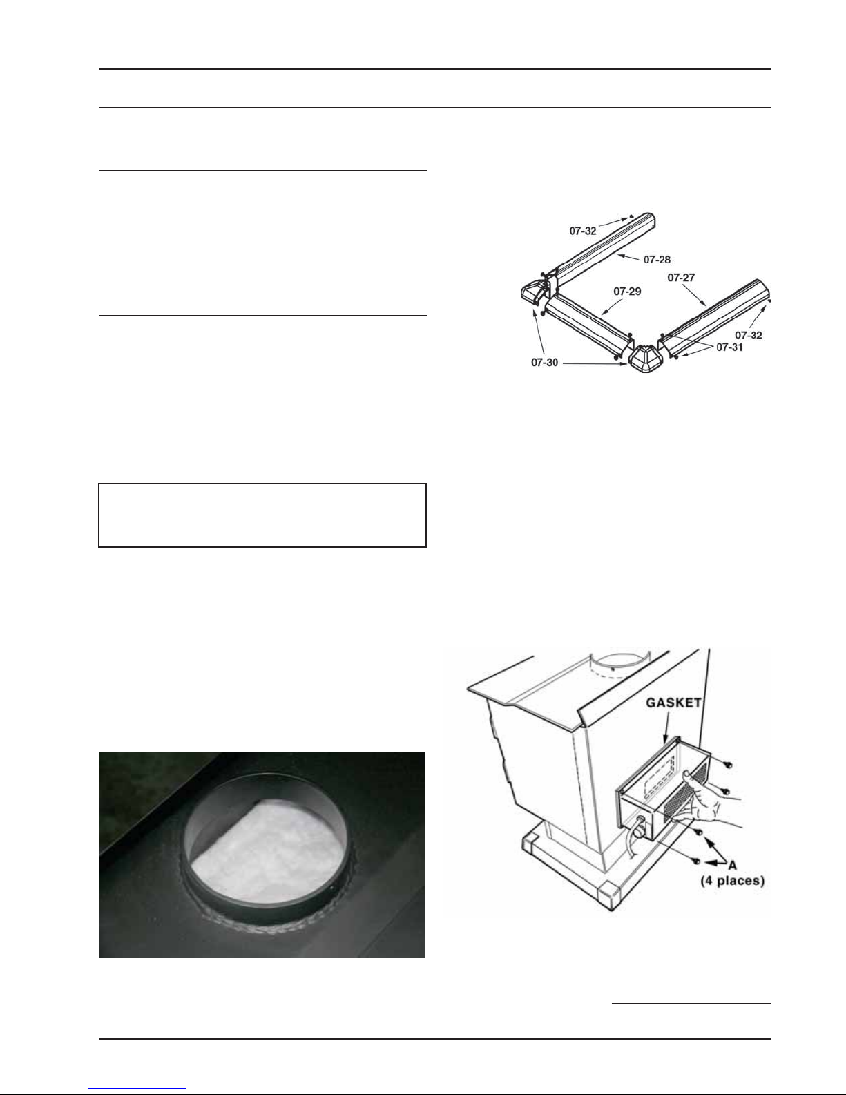
NOTICE: DO NOT REMOVE CERAMIC BLANKET
material from inside stove pipe opening (figure 1).
This blanket provides an air seal on the side walls
of the stove to direct combustion gasses over the
secondary combustion tubes before exiting via
the chimney. DO NOT REMOVE THE CERAMIC
BLANKET or your stove will not operate properly.
2. Stove may be lightened for positioning by removing
fire brick. Note position and arrangement of bricks.
Firebrick, Ash Drawer & Ash Cover MUST be replaced before use. DO NOT USE with missing or
cracked fire brick.
Figure 2
Base Skirting
3. Assemble the pedestal base skirting (figure 2). Attach two corner pieces (07-30) to the center section
(07-29) of skirting and secure with four (4) 3/8˝ long
truss head sheet metal screws (07-31).
4. Attach the side skirting sections (07-27 & 07-28)
to the corner pieces and secure with four (4) truss
head screws (07-31).
5. Slide the U-shaped skirting assembly around the
pedestal base and secure with two 1/4˝ long pan
head sheet metal screws (07-32) at the rear corners.
OPTIONAL BLOWER ASSEMBLY
1. For Optional Blower Assembly, note the position of
the blower opening in the rear of the stove (fig. 3).
DO NOT
REMOVE!
Figure 1 – DO NOT REMOVE CERAMIC BLANKET
from inside stove pipe opening. This is NOT
packing material but an integral component
of the stove combustion system.
VGZ-031 / 20120619.1 www.vogelzang.com TR007 PONDEROSA™ / Page 5
Figure 3 – Attach Optional Blower to Stove Body
2. Place blower gasket onto blower assembly so as
not to obstruct the air flow from the fan.
3. Mount the blower assembly to the back of the stove
continued on next page

ASSEMBLY INSTRUCTIONS . . . continued
aligning the fan opening to the opening in the back
of the stove. Secure with four sheet metal screws.
4. After assembly, check to make sure fire brick are
properly positioned and ash clean out cover is in
place.
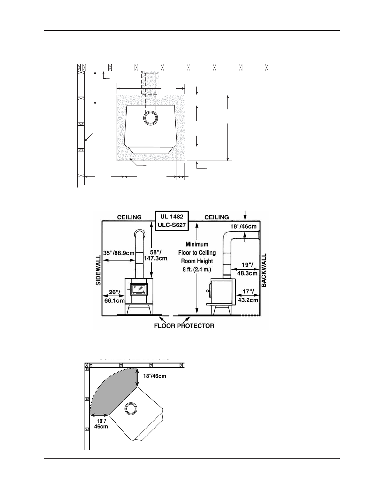
LOCATING STOVE
1. The stove must be placed on solid concrete, solid
masonry, or when installed on a combustible floor,
on an Underwriters Laboratories Listed Type 2 floor
protector listed to UL standard UL 1618, such as
Hy-C or Imperial Model UL4056BK. Floor protector
must be 1/2˝/13mm minimum thickness (R value
= 1.19, K value = 0.84 see page 23 for calculation
formulas) non-combustible material or equivalent.
The floor protector must extend at least 18˝/46cm
beyond the front of the access door, 8˝/21cm to
the sides, 8˝/21cm beyond the rear and must
extend under and 2˝/50mm beyond either side of
the stove pipe if it is elbowed towards a wall. (See
figures 4 – 6 and consult local building codes and
fire protection ordinances.)
CAUTION: FIRE HAZARD. CARPETING AND
OTHER COMBUSTIBLE MATERIAL SHALL
NOT COVER THE FLOOR PROTECTOR. THESE
MATERIALS MUST REMAIN OUTSIDE OF COMBUSTIBLE CLEARANCES, SEE FIG. 5 – 7
2. The room in which the stove is installed must have
a minimum floor to ceiling height of 8 ft. (2.4 m).
3. The stove must have its own flue. Do not connect this unit to a chimney flue serving other
appliances. DO NOT CONNECT TO ANY AIR
DISTRIBUTION DUCT OR SYSTEM.
4. After observing the clearances to combustible materials (figures 4 – 6), locate your floor
protector accordingly (figure 4) and carefully place the stove in your selected location.
Install connector pipe, elbows, and thimble as
required, utilizing either a recently cleaned and
inspected 6˝/152mm lined masonry chimney or a
6˝/152mm i.d. manufactured chimney system listed
to UL 103 HT (US)/ULC-S629 (CDN).
5. Use round 6˝/152mm dia., minimum 24 MSG black
or 26 MSG blue steel stove pipe to connect the
stove to the chimney. Do not use galvanized stove
pipe. NOTE: Mobile home installations require
double-wall UL 103 HT high-temp connector
pipe. Secure connector pipe to the flue collar with
three (3) equally spaced sheet metal screws to
5. Route the power cord away from stove. Do not
allow the power cord to touch any hot surfaces.
Keep power cord at least 12˝ from stove surfaces.
6. Once stove is positioned, plug power cord into a
grounded 120v outlet.
firmly hold the pipe sections together. DO NOT
CONNECT THIS STOVE TO ANY AIR DISTRIBUTION OR DUCT SYSTEM.
6. Recheck clearances from the stove, connector stove pipe, and corner clearances using the illustrations in figures 4 – 6 and
your local building codes or fire protection
ordinances.
NOTE: ANY WALL CONTAINING COMBUSTIBLE MATERIAL SUCH AS WOODEN STUDS OR
DRYWALL AND FACED WITH BRICK OR STONE
MUST BE CONSIDERED A COMBUSTIBLE
SURFACE.
7. NOTICE: for installation in a manufactured/
mobile home (USA only), please see specific
requirements on page 10.
8. The clearances provided are minimum
dimensions set by US standard UL 1482-2011 &
ULC-S627-00, tested and applied by OMNI-Test
Laboratories, Inc. the manufacturer’s testing agency. Installation of this stove must
comply with the latest edition of NFPA 211
(US)/CAN/CSA-B365 (CDN) for reduced
clearances and/or your local building code
rulings. Use whichever minimum dimensions are
LARGEST.
Clearances listed and shown MUST be adhered to
for safe operation of this appliance. CLEARANCES
MAY NOT BE REDUCED BY ANY MEANS IN USA
OR CANADA.
9. This stove meets U.S. Test Standard: UL 14822011& Canadian Standard: ULC-S627-00.
CAUTION: KEEP FURNISHINGS AND OTHER
COMBUSTIBLE MATERIALS AWAY FROM THE
STOVE.
NOTE: BEFORE FIRING WOODSTOVE SLIDE
FIREBRICKS TOWARDS THE REAR SO NO
GAPS REMAIN BETWEEN BRICKS.
Page 6 / TR007 PONDEROSA™ Vogelzang International Corp. VGZ-031 / 20120619.1
LOCATING STOVE . . . continued
COMBUSTIBLE CONSTRUCTION IN ACCORDANCE WITH US NFPA 211
CLEARANCES | TOP VIEW
17"/
BACKWALL
43.2cm
min
SIDEWALL
26"/66.1cm
min.
PROTECTOR
24"/61cm
Figure. 4 – TOP VIEW Minimum Clearance Dimensions from Combustible Surfaces
DASHED LINES SHOW HORIZONTAL CHIMNEY CONNECTOR
AND ADDITIONAL FLOOR PROTECTOR REQUIRED BENEATH
40"/
102cm
AND EXTENDING 2"/50.8mm BEYOND
EACH SIDE OF CONNECTOR PIPE
8"/21cm min.
56"/142.3cm
30"/76.2cm
for installation
according to
UL 1482 (US) &
ULC-S627 (CDN)
FLOOR
18"/46cm min.
8"/21cm min.
Minimum
Clearances
Figure 5a – Front View Figure 5b – Side View
VGZ-031 / 20120619.1 www.vogelzang.com TR007 PONDEROSA™ / Page 7
Minimum Clearance Dimensions
from Combustible Surfaces
Figure 6 – Top View
Minimum Corner Clearances
from Combustible Surfaces
18˝/46cm (US & CDN)
continued on next page
LOCATING STOVE . . . continued
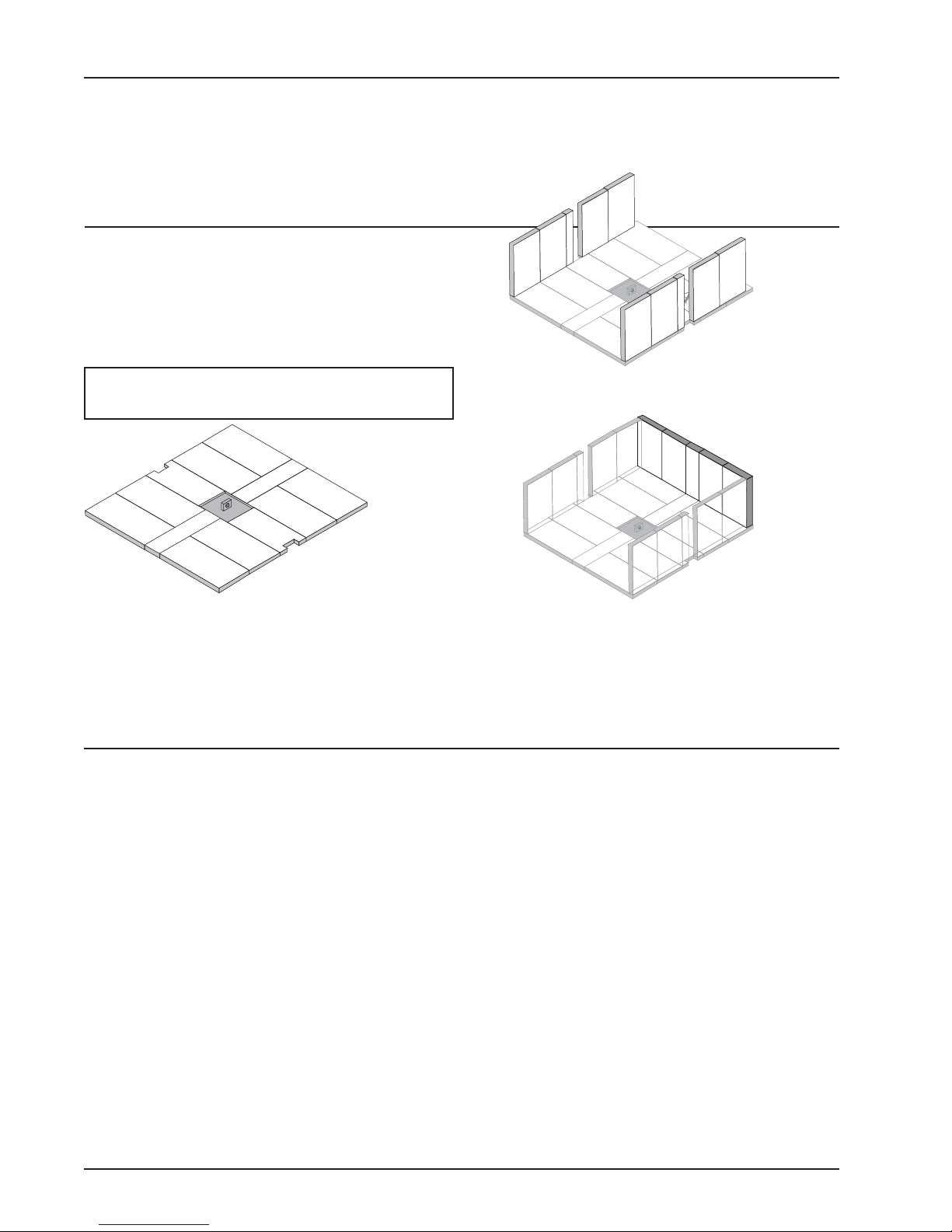
FIREBRICK ASSEMBLY
Firebrick extends the life of your stove and radiates
heat more evenly. Check to see that all firebricks are in
their correct positions and have not become misaligned
during shipping or assembly. If removed for ease of locating stove, firebrick must be replaced before firing.
See figures 7a – 7c, for proper positioning.
CAUTION: NEVER OPERATE STOVE WITH
MISSING OR CRACKED FIRE BRICKS!
A
A
XD
A
A
M
M
A
XD
A
A
Figure 7a – Step 1, Bottom Firebrick Arrangement
Eight (8) A-size, Two (2) M-size, Two (2) XD-size
Fire Brick Dimensions (inches)
A
notches to accommodate air tube
A-size: 9˝x4½˝x1¼˝
M-size: 9˝x2¼˝x1¼˝
XD-size: 8˝x4½˝x1¼˝†
XE-size: 9¾˝x1½˝x1¼˝
† XD bricks have offset
side supports – see illustrations
A
A
A
A
A
XE
A
A
XE
A
A
XD
M
XD
M
A
A
A
A
A
M
A
XD
A
A
A
Side Firebrick Arrangement
Four (4) A-size, Two (2) M-size
A
A
A
A
A
M
A
XD
A
A
A
A
Figure 7c– Step 3,
Back Firebrick Arrangement
Four (4) A-size, One (1) M-size
A
A
A
XE
Figure 7b– Step 2,
M
A
A
A
A
A
XE
CHIMNEY SIZING
Today’s solid fuel heating appliances are much
more efficient than those made in the past. Your heating appliance has been designed to provide the most
efficient transfer of heat possible from the least amount
of fuel.
Controlled combustion is the key to optimum heating performance. Controlled combustion requires a flow
of fresh air into the appliance, across the fuel and is
finally exhausted up the chimney.
Today’s high efficiency stoves transfer more heat
into the living area and less up the chimney. Exhaust
gases are typically at a lower temperature than traditional type stoves. With lower exhaust temperatures, it
is important that the chimney is correctly sized to the
Page 8 / TR007 PONDEROSA™ Vogelzang International Corp. VGZ-031 / 20120619.1
stove. If the chimney diameter is too large, it will be difficult to raise the chimney flue temperature to provide for
adequate draft. This may result in a poor burn, smoke
spillage, and rapid creosote creation. A 6”/152mm
diameter chimney is best suited for this stove.
Your heating appliance must have a minimum of a
6”/152mm diameter chimney. Maximum chimney
diameter must not exceed 10˝ /254mm or have a cross
sectional area greater than 85 sq. in. /550cm
Proper draft for this heating appliance is minimum of
0.05 w.c. (water column measurement) and is required
to prevent back puffing, smoke spillage and prevent
safety hazards.
2
.
 Loading...