

Vogelzang International HighlaNDER TR003 Owner's Manual
HigHlaNDER
NorthlineExpress.com
http://www.northlineexpress.com
Toll-Free 1-866-667-8454
HigH
EfficiENcy WOODsTOvE
EPA Certified (5.76 grams/hr)
model TR003 Owners manual
(save this manual for future reference)
™
READ ALL INSTRUCTIONS CAREFULLY
BEFORE STARTING THE INSTALLATION
OR OPERATING THE STOVE. FAILURE TO
FOLLOw INSTRUCTIONS mAY RESULT
IN PROPERTY DAmAGE, BODILY INjURY,
OR EVEN DEATH.
DO NOT USE THIS STOVE IN A
mOBILE HOmE, mANUFACTURED HOmE,
TRAILER OR TENT — NO EXCEPTIONS!
This stove meets
Test Standards:
UL 1482-1996 U.S. &
ULC-S627Canada
SAFETY INSTRUCTIONS
SAFETY NOTICE: IF THIS STOVE IS NOT PROPERLY INSTALLED A HOUSE/BUILDING FIRE
mAY RESULT. FOR YOUR SAFETY, CONTACT LOCAL BUILDING OR FIRE OFFICIALS ABOUT
PERmITS, RESTRICTIONS, AND INSTALLATION REqUIREmENTS FOR YOUR AREA.
READ ALL INSTRUCTIONS CAREFULLY.
1. The installation of this stove must comply
with your local building code rulings. Please
observe the clearances to combustibles (see
reference figures 1–3). Do not place furniture or other objects within the clearance
area.
2. Verify that the stove is properly installed
before firing the stove for the first time.
After reading these instructions, if you have
any doubt about your ability to complete
your installation properly, you must obtain the services of a professional licensed
installer familiar with all aspects of safe
and correct installation. DO NOT use
temporary or makeshift compromises
during installation.
3. DO NOT store wood, flammable liquids
or other combustible materials too close to
the unit. Refer to certification label on back
of unit and reference figures 1 – 3 in this
manual.
4. Do not install this stove in a mobile
home, manufactured home, trailer or tent
(NO EXCEPTIONS! per HUD Federal
Standard: 24 CFR Ch.XX).
5. If any parts are missing or defective, please
notify the dealer or manufacturer immediately.
DO NOT OPERATE A STOVE THAT IS
MISSING ANY PARTS!.
6. Do not tamper with combustion air control
beyond normal adjustment capacities.
7. Always connect this stove to a chimney and
vent to the outside. Never vent to another room
or inside a building. DO NOT CONNECT
THIS UNIT TO A CHIMNEY FLUE SERVING ANOTHER APPLIANCE.
8. Do NoT coNNecT a wood burning stove
to an aluminum Type B gas vent. This is not
safe. Use approved masonry or a UL 103 HT
(U.S) / ULC-S629 (Canada) Listed Residential Type and Building Heating Appliance
Chimney. Use a 6” diameter chimney, that
continued on next page
VGZ-028 / 030707.1 TR003 HIGHLANDER™ / Page 1
Vogelzang International Corporation
400 West 17th Street
Holland, Michigan 49423
www.vogelzang.com
Phone: 1-616-396-1911
Fax: 1-616-396-1971

SAFETY INSTRUCTIONS continued…
NorthlineExpress.com
http://www.northlineexpress.com
Toll-Free 1-866-667-8454
is high enough to give a good draft. (See
specifics in Chimney Connections instructions).
9. Be sure that your chimney is safely constructed
and in good repair. Have the chimney inspected
by the fire department or a qualified inspector.
Your insurance company should be able to
recommend a qualified inspector.
10. Creosote or soot may build up in the chimney
connector and chimney and cause a house/
building fire. Inspect the chimney connector
and chimney twice monthly during the heating
season and clean if necessary. (See Chimney
Maintenance, page 12).
11. In the event of a chimney fire, turn the air
control to closed position, leave the building and
CALL THE FIRE DEPARTmENT
ImmEDIATELY! Have a clearly understood
plan on how to handle a chimney fire by contacting your local or provincial fire authority
for information on proper procedures in the
event of a chimney fire.
12. To prevent injury, do not allow anyone to use
this stove who is unfamiliar with the correct
operation of the stove.
13. Do not operate stove while under the
influence of drugs or alcohol.
14. For further information on using your stove
safely, obtain a copy of the National Fire
Protection Association (NFPA) publication,
“Using Coal and Wood Stoves Safely” NFPA
No. HS-10-1978. The address of the NFPA is
Batterymarch Park, Quincy, MA 02269.
15. Dispose of ashes in a metal container with a
tight fitting lid. Keep the closed container on
a noncombustible floor or on the ground, well
away from all combustible materials. Keep the
ashes in the closed container until all cinders
have thoroughly cooled. The ashes may be
buried in the ground or picked up by a refuse
collector.
16. The paint used on your stove may give off
smoke and/or odor during the first fires. This
may occur during the first 12 to 15 fires until
the paint has cured. After the paint has cured
this will end and not reoccur. Persons with
lung conditions or owners of susceptible
domestic pets (such as birds) should take
prudent precautions. Open windows and doors
as needed to clear smoke and odor. If the stove
is overfired, paint discoloration will occur.
17. This stove has a painted surface which
is durable but it will not stand rough handling
or abuse. When installing your stove, use care
in handling. Clean with soap and warm water
when stove is
NoT hot. Do not use any acids
or scouring soap, as these solvents wear and
dull the finish.
18. The walls of the firebox may become slightly
distorted after a period of use. A slight distortion will not affect the operation of the stove.
19. While stove is in operation, all persons,
especially young children should be alerted to
the hazards from high surface temperatures.
Keep away from a hot stove to avoid burns or
clothing ignition.
20. If small children will be in the same room
as the stove during operation, provide a
sturdy barrier to keep them at a save distance
from the stove.
NEVER LEAVE SmALL
CHILDREN UNSUPERVISED when they
are in the same room as the stove.
21. Keep stove area clear and free from all
combustible materials, gasoline, and other
flammable vapors and liquids.
22. To prevent burns always wear protective
clothing, leather hearth gloves and eye
protection, while tending the fire.
23. While in operation, keep the feed door closed
and secured at all times except while tending
the fire.
24. Do not overfire the stove. Overfiring will
occur if the feed door is left open during
operation. Such actions can result in very
dangerous operating conditions.
25. NO NOT ELEVATE FIRE! Build fire directly
on the bottom of the firebox. This stove has not
been tested with the use of grates, andirons, or
other means of elevating fire and should not be
used.
26. All power cords and electrical appliances
and/or assemblies must be kept outside of the
clearance dimensions shown in this manual for
combustible materials.
NOTE: A LICENSED PROFESSIONAL HEATING AND COOLING CONTRACTOR SHOULD
BE CONSULTED IF YOU HAVE qUESTIONS
REGARDING THE INSTALLATION OF THIS
SOLID FUEL BURNING APPLIANCE.
Page 2 / TR003 HIGHLANDER™ VGZ-028 / 030707.1

ASSEmblY INSTRUCTIONS
NorthlineExpress.com
http://www.northlineexpress.com
Toll-Free 1-866-667-8454
NOTICE: Vogelzang International Corp. grants no warranty, stated or implied, for the installation or maintenance of
your wood stove and assumes no responsibility of any incidental or consequential damages.
TOOLS AND mATERIALS REqUIRED FOR INSTALLATION
tools
• Pencil
• 6 foot Folding Rule or Tape measure
• Tin Snips
• Drill: Hand or Electric
• 1/8” dia. Drill Bit (for sheet metal screws)
• Screwdrivers (blade and Phillips type)
• 14mm Nut Driver or Ratchet with 14mm Socket
• Safety Glasses
• Gloves
materials
(NOTE: The following items are NOT included with your stove)
Flooring Protection: 35” x 41” as specified (see page 4)
Chimney Connection Pipe: 6” black steel (24 ga. min.) straight
stove pipe or elbow (as required)
1/2” Sheet metal Screws
Chimney: Existing 6” Lined masonry Chimney or 6” Inside Dia.
Listed Type HT chimney.
Furnace Cement (manufacturer recommends Rutland Code 78
or equivalent)
CAUTION: STOVE IS HEAVY. mAkE SURE YOU
HAVE ADEqUATE HELP AND USE PROPER
LIFTING TECHNIqUES wHENEVER mOVING
STOVE.
1. Uncrate the stove and remove cardboard pack-
ing and protective poly bag. Remove pedestal
base (#5) from carton. (Save cardboard for
further assembly.)
2. Remove parts from inside stove. Parts include:
Blower Assembly (#1), Pedestal Front (#4),
two (2) Pedestal Sides (#3), Pedestal Back
(#2), and Hardware Pack (#27) located inside
firebox.
NOTE: Stove may be lightened during instal-
lation by removing fire brick. Replace firebrick
before using. There are three different sizes
brick. Note the location of each while remov-
ing or refer to illustration 1 for proper location
inside firebox.
3. Assemble pedestal using fasteners provided
in hardware pack. Attach both sides (#3) to
pedestal front (#4) then attach pedestal back
to sides.
4. Place flattened carton on floor and place base
(#5) face side up on the carton.
5. Place pedestal assembly on top of base. Align
holes in pedestal sides with holes in the base.
Insert bolts into each hole.
6. Carefully tip the base assembly back, place a
lockwasher and thread a nut onto each bolt.
Tighten all pedestal hardware.
7. Replace the pedestal assembly to the upright
position.
8. After properly locating floor protector (fig 1,
page 4) to accomodate minimum stove clearances, place pedestal in position on floor protector.
9. Carefully position stove body onto base assembly. Angle brackets attached to bottom of
stove must fit inside pedestal assembly. Using
self-tapping screws, attach pedestal base to
stove using two screws on each side.
NOTE: Stove body is HEAVY. Make sure
you have adequate help to lift stove body onto
pedestal and use proper lifting techniques.
10. Attach blower assembly (#1) to the bottom rear
of stove. Use two scres to attach blower to the
underside of stove and two screws tot attach
blower to pedestal base.
11. Route the power cord away from stove. Do not
allow the power cord to touch any hot surfaces.
Keep power cord at least 12” from stove surfaces.
12. Once stove is positioned, plug power cord into
a grounded 120v outlet.
lOCATINg STOvE
1. The stove must be placed on solid concrete,
solid masonry, or when installed on a combustible floor, on a listed floor protector, such
as Hy-C or Imperial Model UL 3648BK or
equivalent with 0.8 R-factor. (NOTE: to calculate R-value of alternative materials see page
17). The base must extend at least 18” beyond
the front of the access door, 8” to the sides
of fuel opening, and must extend under and
2 inches beyond either side of the stove pipe
if it is elbowed towards a wall. (See figures 1
& 3 and consult local building codes and fire
protection ordinances). A grouted ceramic
floor tile installed per local building code is
considered a durable equivalent.
Continued on next page
VGZ-028 / 030707.1 TR003 HIGHLANDER™ / Page 3
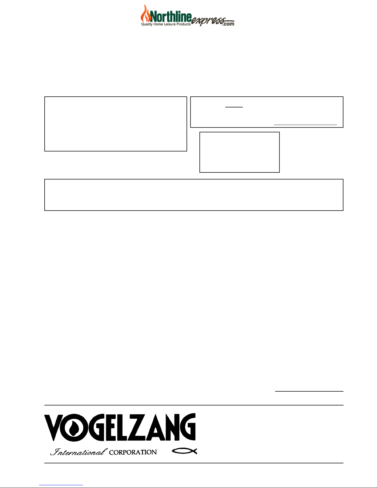
lOCATINg STOvE …continued
FLOOR
PROTECTOR
DASHED LINES SHOw HORIzONTAL CHImNEY CONNECTOR
AND ADDITIONAL FLOOR PROTECTOR REqUIRED BENEATH
AND EXTENDINg 2” bEYOND EACh SIDE
NON COmBUSTIBLE CONSTRUCTION IN ACCORDANCE wITH NFPA 211
BACkwALL
SIDEwALL
8"min.
17"
41"
16"min.
6"min.23"
15"
min.
12"min
TOP VIEw
35"
NorthlineExpress.com
http://www.northlineexpress.com
Toll-Free 1-866-667-8454
CAUTION: (FIRE HAzARD) CARPETING AND
OTHER COmBUSTIBLE mATERIAL SHALL
NOT COVER THE FLOOR PROTECTOR. THESE
mATERIALS mUST REmAIN OUTSIDE OF
COmBUSTIBLE CLEARANCES, SEE FIG. 1 – 3.
2. The stove must have its own flue. Do NoT
coNNecT This uNiT To a chimNey
flue serviNg oTher aPPliaNces.
3. After observing the clearances to combustible materials (figures 1–3), locate your floor
protector accordingly (figure 1) and carefully place the stove in your selected location.
Install stove pipe, elbows, and thimble as
required, utilizing either a recently cleaned
and inspected 6” masonry chimney or a 6” i.d.
listed chimney.
4. Use 6” round black stove pipe, not
galvanized stove pipe. Secure pipe sections
with three (3) sheet metal screws in each stove
pipe and/or elbow joint to firmly hold the pipe
sections together.
Do NoT coNNecT This
sTove To aNy air DisTribuTioN or
DucT sysTem.
5. Recheck clearances from the stove,
connector stove pipe, and corner clearances
using the illustrations in figures 1–3 and
your local building codes or fire protection
ordinances.
NOTE: Drywall faced with brick or stone must
be considered a combustible surface.
6. Do Not iNstall this stove iN a mobile
home, maNufactureD home, trailer
or teNt – NO EXCEPTIONS! (HUD Federal
Standard: 24 CFR Ch.
XX)
7. The clearances provided are minimum
dimensions determined by Omni Test Laboratories, Inc., the manufacturer’s testing
laboratory. Installation of this stove must
comply with the latest edition of NFPA 211
for reduced clearances and/or your local building code rulings. Use whichever minimum
dimensions are LARGEST.
Failure to follow these minimum clear-
ance requirements may result in an unsafe
installation and could cause a fire.
8. This stove meets U.S. Test Standard:
UL 1482-1996 and Canadian Test Standard
ULC-S627.
9. Always locate stove to provide a source of fresh
air into the room where the unit is installed.
Failure to do so may result in air starvation of
other fuel burning appliances and the possible
development of hazardous conditions.
CAUTION: kEEP FURNISHINGS AND OTHER
COmBUSTIBLE mATERIALS AwAY FORm THE
STOVE AND OUTSIDE mINImUm CLEARANCES.
CAUTION: REPLACE FIREBRICkS BEFORE
FIRING wOODSTOVE. POSITION FIREBRICkS
SO NO GAPS REmAIN BETwEEN BRICkS.
Fig. 1 – TOp VIEw Minimum Clearance Dimensions from Combustible Surfaces
Page 4 / TR003 HIGHLANDER™ VGZ-028 / 030707.1
Continued on next page
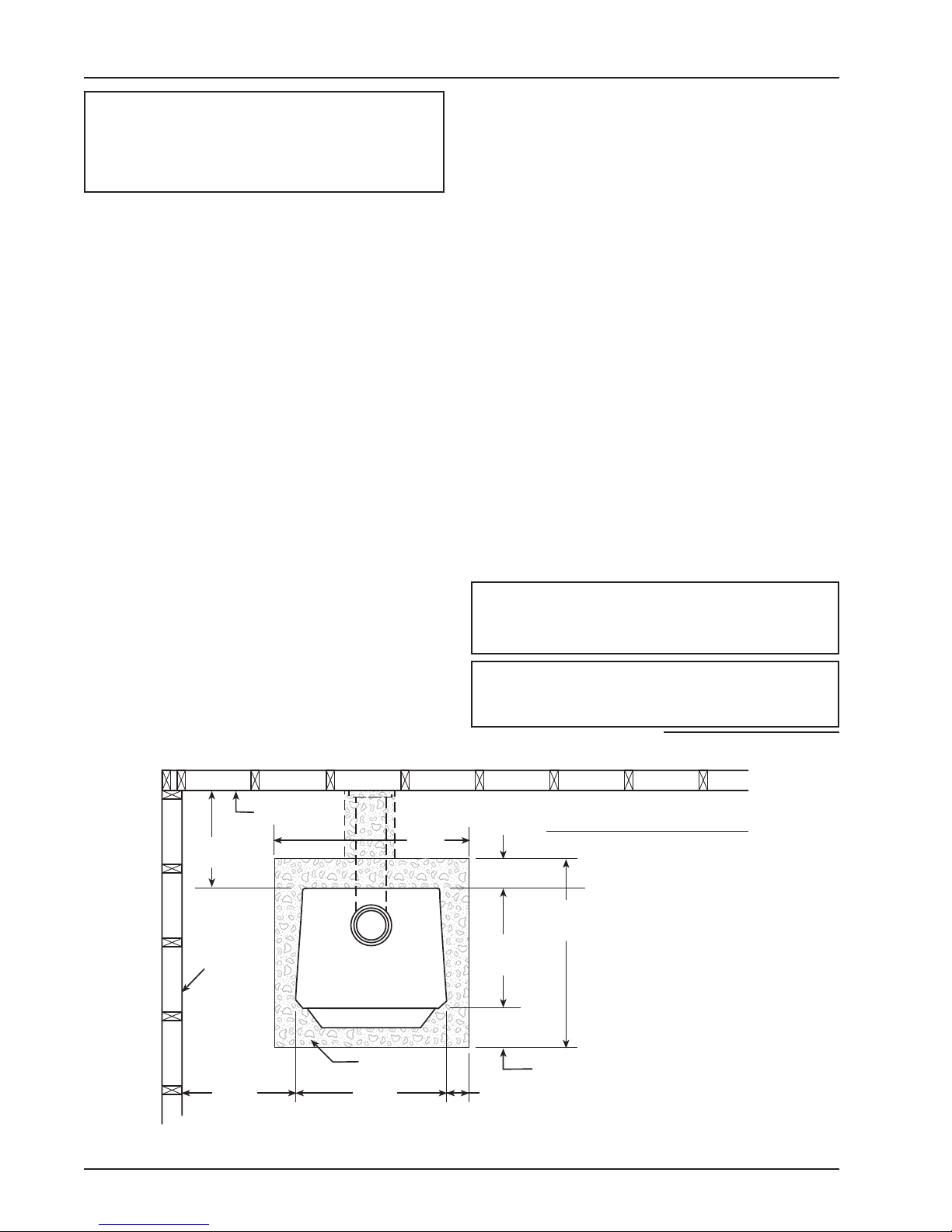
lOCATINg STOvE …continued
12"
12"
CORNER CLEARANCES
A A
C
B
A
A
B
NorthlineExpress.com
http://www.northlineexpress.com
Toll-Free 1-866-667-8454
Fig. 2 – Top View
Minimum Corner Clearances
from Combustible Surfaces
Fig. 3b – Side View
Minimum Clearance Dimensions
from Combustible Surfaces
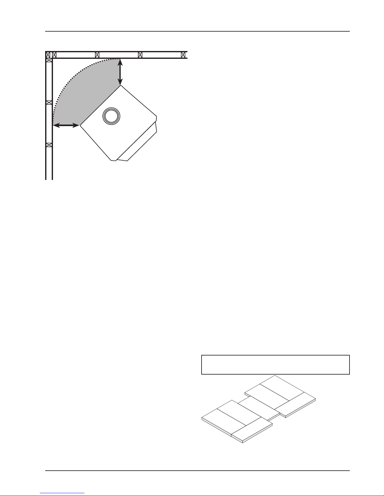
FIREBRICk ASSEmBLY
Firebrick extends the life of your stove and
radiates heat more evenly. Check to see that all
firebricks are in their correct positions and have not
become misaligned during shipping or assembly.
If removed for ease of locating stove, firebrick
must be replaced before firing. See diagrams, fig.
4a – 4c, for proper positioning.
CAUTION: NEVER OPERATE STOVE wITH
mISSING OR CRACkED FIRE BRICkS!
Fig. 3a – Front View
VGZ-028 / 030707.1 TR003 HIGHLANDER™ / Page 5
Minimum Clearance Dimensions
from Combustible Surfaces
Four (4) A-Size
Two (2) B-Size
One (1) C-Size
Fig.4a– Step 1, Bottom Firebrick Installation
lOCATINg STOvE
A A
C
B
A A
B
A
A
B
A
A
B
A
C
C
A
A A
C
B
A A
B
A
A
B
A
A
B
NorthlineExpress.com
http://www.northlineexpress.com
Toll-Free 1-866-667-8454
Fire Brick Dimensions
A-Size: 9”x4½”x1¼”
B-Size: 9”x2¾”x1¼”
C-Size: 9”x3¼”x1¼”
Four (4) A-Size
Two (2) B-Size
Fig.4b– Step 2, Side Firebrick Installation Fig.4c– Step 3, Back Firebrick Installation
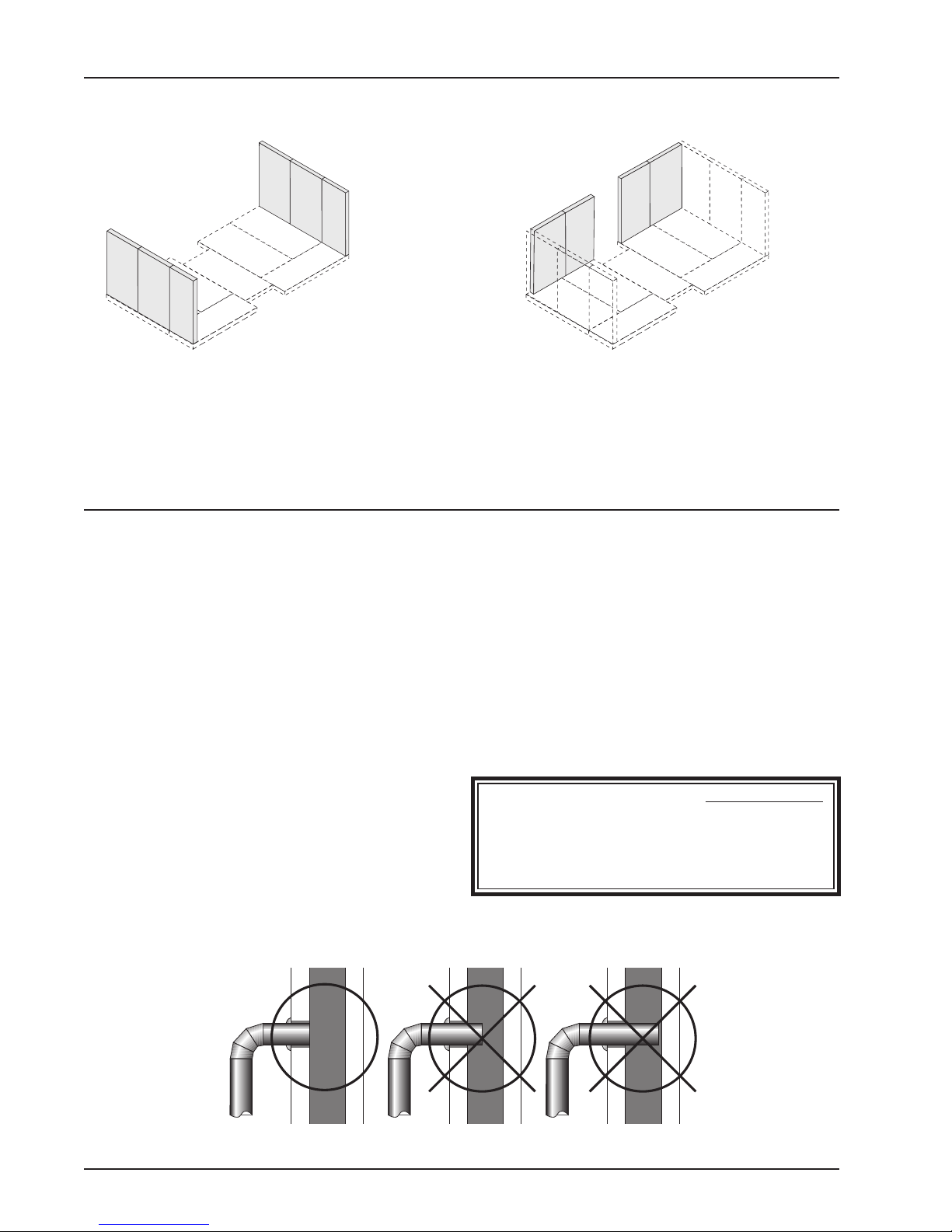
CONNECTOR PIPE INSTAllATION
1. The tapered end of the connector stovepipe fits
into the stove flue collar.
2. Horizontal pipe runs must slope upwards
towards the chimney at least 1/4” per foot of
horizontal run.
3. You must have at least 18 inches of clearance
between any horizontal piping and the ceiling.
4. The pipe cannot extend into the chimney flue
(figure 5).
5. Secure pipe/elbow sections with three (3) sheet
metal screws at each joint to make the piping
rigid.
6. It is recommended that no more than two (2)
90 degree bends be used in the stovepipe installation. The use of more than two 90 degree
bends may decrease the amount of draw and
possibly cause smoke spillage. Where possible,
use only corrugated (nonadjustable) elbows.
These provide a better seal.
7. The connector pipe must not pass through an
attic or roof space, closet, or any concealed
space, or floor, ceiling, wall or combustible
construction. (See Chimney Connector Systems & Clearances, page 17). A UL 103 HT
Listed (U.S.) or ULC-S629 (CANADA) chimney must be used from the first penetration of
ceiling or wall to the chimney cap. Never use
single wall connector pipe as a chimney - a
house fire could result.
NOTE: CONNECTOR PIPE IS NOT INClUDED.
TO PURCHASE, VISIT YOUR LOCAL HARDwARE, HOmE OR BUILDING CENTER. SEE
“LOCATING STOVE” PAGE 4 FOR ADDITIONAL
SPECIFICATIONS.
Two (2) A-Size
Two (2) C-Size
CORRECT wRONG wRONG
Page 6 / TR003 HIGHLANDER™ VGZ-028 / 030707.1
Fig.5 – Stovepipe/Flue Connections
 Loading...