

Vogelzang International DEFENDER TR001B Owner's Manual
DEFENDER
HIGH EFFICIENCY
AIR-TIGHT WOODSTOVE
EPA Certified (4.22 grams/hr)
Model TR001B Owners Manual
(Save These Instructions)
Le manuel de langue français est disponible à www.vogelzang.com
French language manual is available at www.vogelzang.com
™
Report No. 235-S-01c-2
READ ALL INSTRUCTIONS CAREFULLY
BEFORE INSTALLING OR OPERATING
THIS STOVE. FAILURE TO FOLLOW INSTRUC-
TIONS MAY RESULT IN PROPERTY DAMAGE,
BODILY INJURY, OR EVEN DEATH.
REFER TO MARKINGS ON STOVE LABELS FOR
ADDITIONAL INFORMATION.
SAFETY NOTICE: IF THIS STOVE IS NOT PROPERLY INSTALLED, A HOUSE/BUILDING FIRE MAY
RESULT. FOR YOUR SAFETY, CONTACT LOCAL OR MUNICIPAL BUILDING OR FIRE OFFICIALS
ABOUT PERMITS, RESTRICTIONS, AND INSTALLATION REQUIREMENTS FOR YOUR AREA.
US: UL 1482-2010 & CDN: ULC-S627-00
NOTE: IT IS RECOMMENDED INSTALLATION
BE COMPLETED BY A QUALIFIED HEATING
DO NOT INSTALL IN A MOBILE HOME.
This stove meets test standards:
EQUIPMENT INSTALLER!
Vogelzang International Corporation
400 West 17th Street
Holland, Michigan 49423
www.vogelzang.com
Phone: 1-616-396-1911
Fax: 1-616-396-1971
TR001B | 20120125.0 www.vogelzang.com DEFENDER™ | Page 1

SAFETY INSTRUCTIONS-Read All Instructions Carefully.
1. The installation of this stove must comply with your
local building code rulings. Please observe the clearances to combustibles (see reference figures 6–8).
Do not place fuel, furniture or any other objects within
the clearance area.
2. Verify that the stove is properly assembled and
installed before firing the stove for the first time.
After reading these instructions, if you have any
doubt about your ability to complete your installation
properly, you must obtain the services of a
professional licensed installer familiar with all
aspects of safe and correct installation. DO NOT
use temporary or makeshift compromises
during installation. There must be NO DEVIATION
OR ALTERATION OF ANY KIND from the very specific instructions spelled out in this instruction manual
as it pertains to the installation of this woodstove.
NO EXCEPTIONS!
3. DO NOT store wood, kindling, flammable liquids
or other combustible materials in the vicinity of the
appliance. Refer to certification label on back of unit
and reference figures 6–8 in this manual.
4. DO NOT INSTALL THIS STOVE IN A MOBILE
HOME, MANUFACTURED HOME, TRAILER OR
TENT NO EXCEPTIONS! (HUD Federal Standard:
24 CFR Ch.XX).
5. DO NOT ELEVATE THIS STOVE BY ANY MEANS.
(i.e. bricks under legs, cement blocks) Stove legs
must set directly upon the solid-surface non-combustible floor as specified in this stove instruction
manual.
6. DO NOT MODIFY THIS STOVE IN ANY WAY!
Stove must be installed with legs and ash drawer
provided, attached as shown in the instructions.
DO NOT OPERATE WITHOUT ASH DRAWER
OR ASH CLEAN OUT COVER IN PLACE – NO
EXCEPTIONS. Assemble only with original parts as
supplied and shown in this manual. DO NOT OPER-
ATE A STOVE THAT IS MISSING ANY PARTS! If
any parts are missing or defective, please notify
the dealer or manufacturer immediately. Replace
missing, broken or worn parts with factory original
or equivalent parts only.
7. CAUTION: DO NOT ALTER COMBUSTION AIR
CONTROL RANGE TO INCREASE FIRING OR
FOR ANY REASON. Altering or tampering with air
control beyond normal capacity will create unsafe
and hazardous conditions.
8. Always connect this stove to a chimney and vent to
the outside. Never vent to a room or inside a building.
DO NOT CONNECT THIS UNIT TO A CHIMNEY
FLUE SERVING ANOTHER APPLIANCE.
9. DO NOT CONNECT A WOOD BURNING STOVE
TO AN ALUMINUM TYPE B GAS VENT. This is
not safe. Use approved masonry or an Underwriters Laboratories Listed UL 103 HT (US)/ULC-S629
(CDN) Residential Type and Building Heating Appliance Chimney. Use a 6˝/152mm diameter chimney, that is high enough to give a good draft. (See
specifics in Chimney Connections instructions).
10. Be sure that your chimney is safely constructed and
in good repair. Have the chimney inspected by the fire
department or a qualified inspector. Your insurance
company should be able to recommend a qualified
inspector. Chimney connector pipe must be in good
condition. Replace if necessary before using stove.
11. Creosote or soot may build up in the chimney connector and chimney and cause a house/building
fire. Inspect the chimney connector and chimney
twice monthly during the heating season and clean
if necessary. (see Service Hints).
12. In the event of a chimney fire, turn the air controls to
closed positions, leave the building and CALL THE
FIRE DEPARTMENT IMMEDIATELY! Have a clearly
understood plan on how to handle a chimney fire by
contacting your local fire authority for information
on proper procedures in the event of a chimney fire.
After the fire is out, the chimney must be cleaned
and inspected for any stress or cracks before starting
another fire. Check the condition of any combustibles
surrounding the chimney.
13. Ashes should not be allowed to accumulate above
the top of the lower primary air orifice (LPAO, air vent
at front of firebox, just inside of door).
14. DISPOSAL OF ASHES
Ashes should be placed in a steel container with
a tight fitting lid and moved outdoors immediately.
The closed container of ashes should be placed
on a noncombustible floor or on the ground, well
away from all combustible materials, pending final
disposal. If the ashes are disposed of by burial in
soil or otherwise locally dispersed, they should be
retained in the closed container until all cinders have
completely cooled. Other waste shall not be placed
in this container.
15. To prevent injury, do not allow anyone to use this
stove who is unfamiliar with the correct operation of
the stove.
16. Do not operate stove while under the influence of
drugs or alcohol.
17. DO NOT ELEVATE THE FIRE. Build fire directly on
the bottom of the firebox. This stove has not been
tested with the use of grates, andirons or other means
of elevating the fire and must not be used.
Page 2 | DEFENDER™ Vogelzang International Corp. TR001B | 20120125.0

SAFETY INSTRUCTIONS continued…
18. The special paints used on your stove may give
off some smoke and an odor while they are curing during the first 12 to 15 fires. Additional smoke
and odor may be emitted from the light oils used
in construction of the fire box. This should disappear after a short period of time and not occur
again. Persons with lung conditions or owners of
susceptible domestic pets (such as birds) should take
prudent precautions. Open windows and doors as
needed to clear smoke and/or odor. Paint discoloration will occur if the stove is over fired.
19. This stove has a painted surface which is durable
but it will not stand rough handling or abuse. When
installing your stove, use care in handling.
20. CLEAN STOVE FREQUENTLY as soot, creosote
and ash may accumulate. Clean exterior with soap
and warm water when stove is not hot. Do not use
any acids or scouring soap, as these solvents wear
and dull the finish.
21. ALERT ALL PERSONS TO THE HAZARDS OF
HIGH SURFACE TEMPERATURES while stove is
in operation – especially young children. Keep away
from a hot stove to avoid burns or clothing ignition.
22. NEVER LEAVE SMALL CHILDREN UNSUPER-
VISED WHEN THEY ARE IN THE SAME ROOM
AS THE STOVE. If small children will be in the same
room as the stove during operation, provide a sturdy
barrier to keep them at a safe distance from the stove.
23. Keep stove area clear and free from all combustible
materials, gasoline, engine oil, naphtha and other
flammable vapors and liquids.
24. WHILE TENDING THE FIRE ALWAYS WEAR PRO-
TECTIVE CLOTHING, fire retardant hearth gloves
and eye protection, to prevent burns.
25. Never operate this stove without ash drawer, ash
clean out or with the door open except when refueling. Such actions can result in very dangerous
operating conditions.
26. DO NOT OVER FIRE THE STOVE. Over firing
will occur if combustion air is uncontrolled as when
feed door is left open during operation. Such actions
can result in very dangerous operating conditions.
While in operation, keep the feed door closed and
secured at all times except while tending the fire
27. When adding fuel be careful not to smother the fire.
Do not build fires against glass and do not load fuel to
a height or in such a manner that it creates a hazard
when opening the door.
28. NEVER LEAVE THE STOVE UNATTENDED with
door open. Always close the door after ignition.
29. DO NOT CONNECT TO OR USE IN CONJUNC-
TION WITH ANY AIR DISTRIBUTION DUCT WORK
UNLESS SPECIFICALLY APPROVED FOR SUCH
INSTALLATIONS.
30. A WOOD-BURNING STOVE MUST NEVER BE
INSTALLED IN A HALLWAY OR NEAR A STAIRCASE, as it may block egress in the event of a fire.
31. DO NOT INSTALL IN A SLEEPING ROOM.
DO NOT INSTALL IN AN ALCOVE OR INSIDE A
FIREPLACE.
32. Install at least one smoke detector on each floor of
your home. Detectors should be located away from
the heating appliance to avoid false alarms. Detectors
should be located close to sleeping areas. Follow
the smoke detectors manufacturer’s placement and
installation instructions. Maintain smoke detector per
manufacturer’s instructions.
33. CARBON MONOXIDE (CO) HAZARD. A buildup of
CO fumes is toxic and can be fatal. Carbon Monoxide
is a colorless, odorless gas produced during combustion of wood, coal, oil, gas and by other fuel burning
appliances. It is important to have a proper draft and
adequate replacement air ventilation so fumes are
drawn out the chimney. Installed as instructed this
stove is designed to be as safe as possible yet it is
recommended to install a CO detector. Follow the
manufacturer’s recommendations for proper installation and use. It is recommended to be placed at
table-top level (not near the ceiling) to avoid false
alarms. Realize that devices other than a stove (i.e.
motor exhaust) can trigger CO alarms.
If alarm sounds:
• RecognizethesymptomsofCOpoisoning(head-
aches, nausea & drowsiness).
• Increaseventilation(openwindows&doors).
• Makesurestovedoorsand/orlidsareclosedand
secured.
• Checkstoveforsmokingorpufng(open airow
controls).
• Checkchimney&connectorpipeforleaks,block-
age or down-draft conditions.
• CheckCOdeviceforfalsealarm.
34. Keep power cords, electrical appliances and/or assemblies outside of the clearance area shown in this
manual for combustible materials.
35. Consult your municipal building department or fire
officials about restrictions, permits and installation
requirements for your area.
36. For further information on using your stove safely,
obtain a copy of the National Fire Protection
Association (NFPA) publication, “Using Coal and
Wood Stoves Safely” NFPA No. HS-10-1978. Write
NFPA, Batterymarch Park, Quincy, MA 02269.
TR001B | 20120125.0 www.vogelzang.com DEFENDER™ | Page 3

TABLE OF CONTENTS
SAFETY PRECAUTIONS ............................................................................... 2 – 3
TOOLS AND MATERIALS REQUIRED FOR INSTALLATION ............................ 5
ASSEMBLY INSTRUCTIONS .............................................................................. 5
LOCATING THE STOVE ...................................................................................... 6
Minimum Clearances ......................................................................... 6 – 8
FIREBRICK ASSEMBLY ..................................................................................... 8
INSTALLATION .................................................................................................... 9
CONNECTOR PIPE INSTALLATION ................................................................... 9
CHIMNEY SIZING ............................................................................................... 10
CHIMNEY CONNECTIONS ......................................................................... 10 –13
CHIMNEY CONNECTION SYSTEMS & CLEARANCES ................................... 14
OPERATING INSTRUCTIONS
House Fire Hazards, Operating Precautions, Warnings ...................... 15
Wood Types/Sizes .................................................................................... 15
Optimal Fuel Consumption .................................................................... 15
Starting a Fire, Adding Fuel ................................................................... 16
SERVICE HINTS
Creosote Formation, Prevention, Need for Removal .......................... 17
Chimney Draft ......................................................................................... 18
Glass Care & Replacement ................................................................... 19
Door Gasket Replacement .................................................................... 20
OPTIONAL F-6 BLOWER MAINTENANCE & WIRING DIAGRAM ................... 20
PARTS – DEFENDER™ .................................................................................... 21
PARTS – GLASS DOOR .................................................................................... 22
PARTS – FIRE BRICK ....................................................................................... 22
FLOOR PROTECTOR CALCULATIONS ........................................................... 23
NOTE: A PROFESSIONAL, LICENSED HEATING AND COOLING CONTRACTOR MUST
BE CONSULTED IF YOU HAVE QUESTIONS
REGARDING THE INSTALLATION OF THIS
SOLID FUEL BURNING APPLIANCE.
Page 4 | DEFENDER™ Vogelzang International Corp. TR001B | 20120125.0
ASSEMBLY INSTRUCTIONS
NOTICE: Vogelzang International Corp. grants no warranty, stated or implied, for the installation or maintenance of your wood
stove and assumes no responsibility of any incidental or consequential damages.
TOOLS AND MATERIALS REQUIRED FOR INSTALLATION
tools
• Pencil
• 6 foot Folding Rule or Tape Measure
• Tin Snips
• Drill: Hand or Electric
• 1/8” dia. Drill Bit (for sheet metal screws)
• Screwdrivers (blade and Phillips type)
• 9/16” Nut Driver or Ratchet with 9/16” Socket
• Safety Glasses
• Gloves
materials
(NOTE: The following items are NOT included with
your stove and are required for proper installation.)
Flooring Protection as specified (see page 6)
Chimney Connection: 6”/152mm dia. minimum 24 MSG black or
26 MSG blue steel straight stove pipe or elbow(s).
1/2”/13mm Sheet Metal Screws
Chimney: Existing 6˝ Code-approved Lined Masonry Chimney
or 6˝ Inside Dia. UL 103 HT (US)/ULC-S629 (CDN) listed
manufactured chimney.
Furnace Cement (manufacturer recommends Rutland Code 78
CAUTION: STOVE IS HEAVY. MAKE SURE YOU
HAVE ADEQUATE HELP AND USE PROPER
LIFTING TECHNIQUES WHENEVER MOVING
STOVE.
or equivalent)
ing. There are six different sizes brick and two with
notches. Note the location of each while removing
or refer to fig. 9a, b & c (page 6) for proper location
inside firebox.
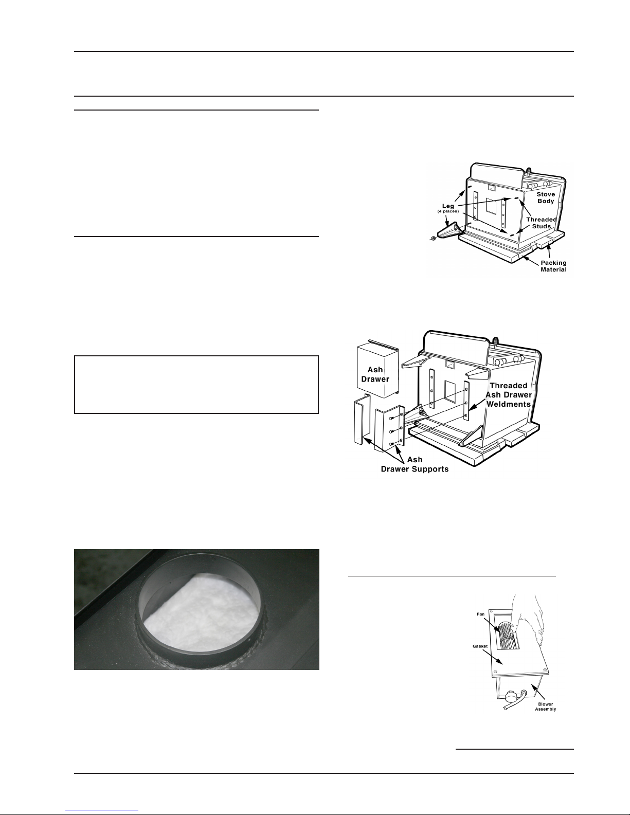
3. Place flattened
carton on floor
and lay the stove
on it’s back.
4. Remove the four
9/16” nuts from
the threaded
studs located on
each corner.
Fig. 2– Attach (4)
Legs
5. Place legs in
position and secure using the nuts removed in
step #4. Tighten nuts securely.
1. Uncrate the stove and remove all packing materials
and protective poly bag.
NOTICE: DO NOT remove ceramic blanket
material from inside stove pipe opening (Fig. 1).
This blanket provides an air seal on the side walls
of the stove to direct combustion gasses over the
secondary combustion tubes before exiting via the
chimney. DO NOT REMOVE the ceramic blanket
or your stove will not operate properly.
DO NOT
REMOVE!
Figure 1 – DO NOT remove ceramic blanket from
inside stove pipe opening. This is NOT packing
material but an integral component of the stove
combustion system.
2. Remove all parts from inside stove. NOTE: Stove
may be lightened during installation by removing
fire brick. Replace firebrick & ash cover before us-
Fig. 3 – Attach
Ash Drawer
6. Next install the Ash Drawer Supports to the
threaded weldments on the bottom of the stove,
fig. 3. Each support uses three threaded bolts as
shown.
7. Carefully lift the stove into an upright position.
OPTIONAL BLOWER ATTACHMENT
(NOT INCLUDED WITH STOVE)
1. Attach blower assembly
(fig. 4) to back of rear
deflector. (fig.5)
NOTE: Make sure ce-
ramic gasket is positioned between rear deflector heat shield and
blower assembly. Use
four screws provided to
fasten the blower to rear
heat shield.
Fig. 4 – Optional
Blower Assembly
continued on next page
TR001B | 20120125.0 www.vogelzang.com DEFENDER™ | Page 5
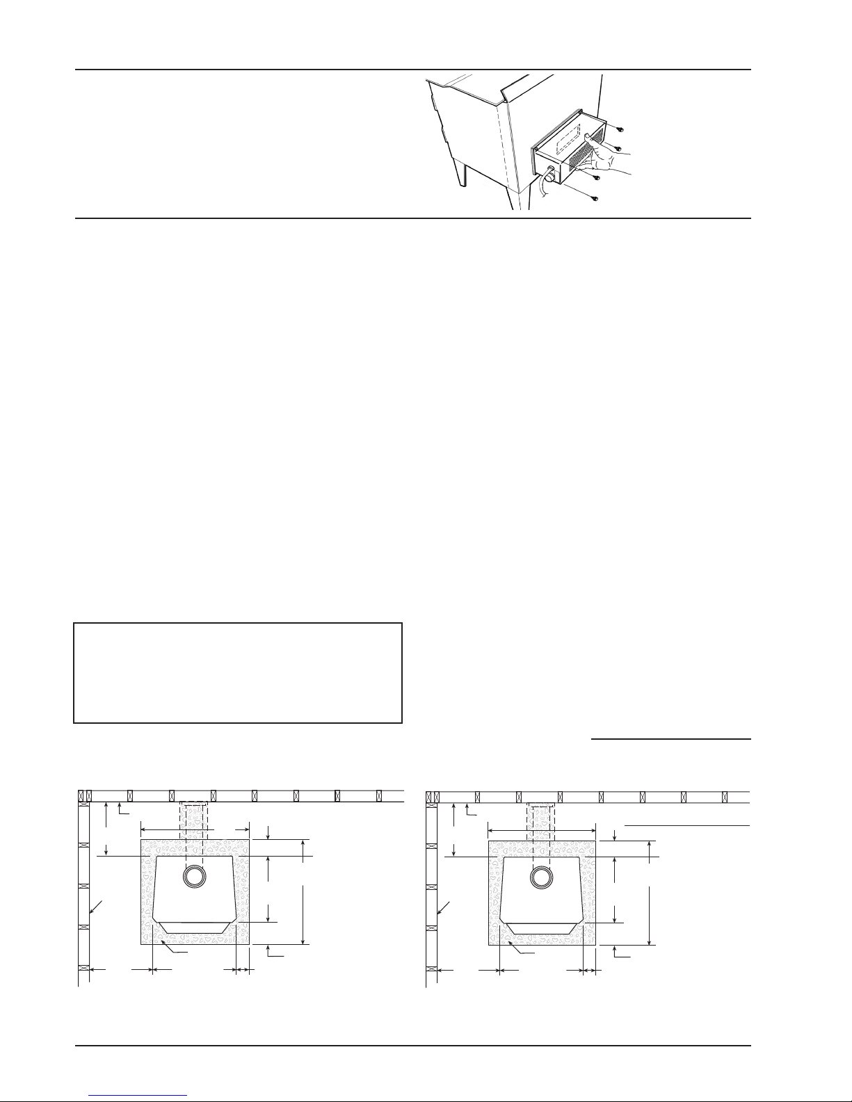
ASSEMBLY (continued)
FLOOR
PROTECTOR
DASHED LINES SHOW HORIZONTAL CHIMNEY CONNECTOR
AND ADDITIONAL FLOOR PROTECTOR REQUIRED BENEATH
AND EXTENDING 2"/5cm BEYOND EACH SID
E
COMBUSTIBLE CONSTRUCTION IN ACCORDANCE WITH US NFPA 211
BACKWALL
SIDEWALL
8"/20.3cm
minimum
18"/46.8cm
44"/112cm
18"/46.8cm min.
8"/20.3cm min.
23"/54.5cm
15"/38.1cm
min.
12"/30.5cm
minimum
TOP VIEW | CANADIAN CLEARANCES
39"/
100cm
TR001B
Minimum
Clearances &
Minimum
Floor Protector
Dimensions
for Canadian
Installation
According to
ULC 5627
2. Route the power cord away from stove. Do not
allow the power cord to touch any hot surfaces. Keep
power cord at least 12˝ from stove surfaces.
3. Once stove is positioned, plug power cord into a
grounded 120v outlet.
LOCATING STOVE
1. The stove must be placed on solid concrete, solid
masonry, or when installed on a combustible floor,
on an listed UL 1618 Type 2 floor protector, such
as Hy-C or Imperial Model UL 3648BK (US) or
UL4048BK (CAN) or equivalent. Floor protector
must be 1/2˝/13mm minimum thickness (“k” value
= 0.84, R value = 0.59, see page 23 for calculation
formulas) non-combustible material or equivalent.
US Requirements: The floor protector must extend
at least 16˝/41cm beyond the front of the access
door, 6˝/15.2cm to the sides, 12˝/30.5cm beyond the
rear and must extend under and 2˝/51mm beyond
either side of the stove pipe connector if it is elbowed towards a wall. (See figures 6–8 and consult
local building codes and fire protection ordinances.)
Canadian Requirements: The base must extend
at least 18˝/46.8cm beyond the front of the access
door, 8˝/20.3cm to the sides, 8˝/20.3cm behind the
stove and must extend under and 2˝/51mm beyond
either side of the stove pipe if it is elbowed towards
a wall. (See figures 6–8 and consult local building
codes and fire protection ordinances).
CAUTION: (FIRE HAZARD) CARPETING AND
OTHER COMBUSTIBLE MATERIAL SHALL
NOT COVER THE FLOOR PROTECTOR. THESE
MATERIALS MUST REMAIN OUTSIDE OF
COMBUSTIBLE CLEARANCES, SEE FIG. 6 – 8.
Fig. 5 – Mount
Blower Assembly to
rear Heat Deflector
2. The room in which he stove is installed must have
a minimum floor to ceiling height of 8 ft./2.4 m & a
minimum stove top to ceiling height of 55˝/140 cm.
3. The stove must have its own flue. Do not connect this unit to a chimney flue serving other
appliances.
4. After observing the clearances to combustible materials (figures 6–8), locate your floor
protector accordingly (figure 6) and carefully place the stove in your selected location.
Install stove pipe, elbows, and thimble as
required, utilizing either a recently cleaned and
inspected 6˝/152mm masonry chimney or a
6˝/152mm i.d. UL 103 HT (US)/ULC-S629 (CDN)
listed manufactured chimney.
5. Use round 6˝/152mm dia., minimum 24 MSG black
or 26 MSG blue steel stove pipe to connect the
stove to the chimney. DO NOT USE GALVANIZED
DUCT PIPE AS A CONNECTOR. Secure pipe
sections with three (3) sheet metal screws no more
than a maximum of 3˝/76mm apart in each stove
pipe and/or elbow joint to firmly hold the pipe sections together. DO NOT CONNECT THIS STOVE
TO ANY AIR DISTRIBUTION OR DUCT SYSTEM.
6. Recheck clearances from the stove,
connector stove pipe, and corner clearances using the illustrations in figures 6–8 and
COMBUSTIBLE CONSTRUCTION IN ACCORDANCE WITH NFPA 211
12"/30.5cm
minimum
SIDEWALL
15"/38.1cm
min.
Page 6 | DEFENDER™ Vogelzang International Corp. TR001B | 20120125.0
TOP VIEW | USA CLEARANCES
DASHED LINES SHOW HORIZONTAL CHIMNEY CONNECTOR
BACKWALL
AND ADDITIONAL FLOOR PROTECTOR REQUIRED BENEATH
35"/
89cm
TR001B
FLOOR
PROTECTOR
23"/54.5cm
AND EXTENDING 2"/5cm BEYOND EACH SIDE
12"/30.5cm
minimum
46"/117cm
18"/45.7cm
6"/15.2cm min.
Fig. 6 – Top View Minimum Clearance Dimensions
Minimum
Clearances &
Minimum
Floor Protector
Dimensions
for United States
Installation
According to
UL 1482-2006
16"/40.6cm min.
from Combustible Surfaces
continued on next page
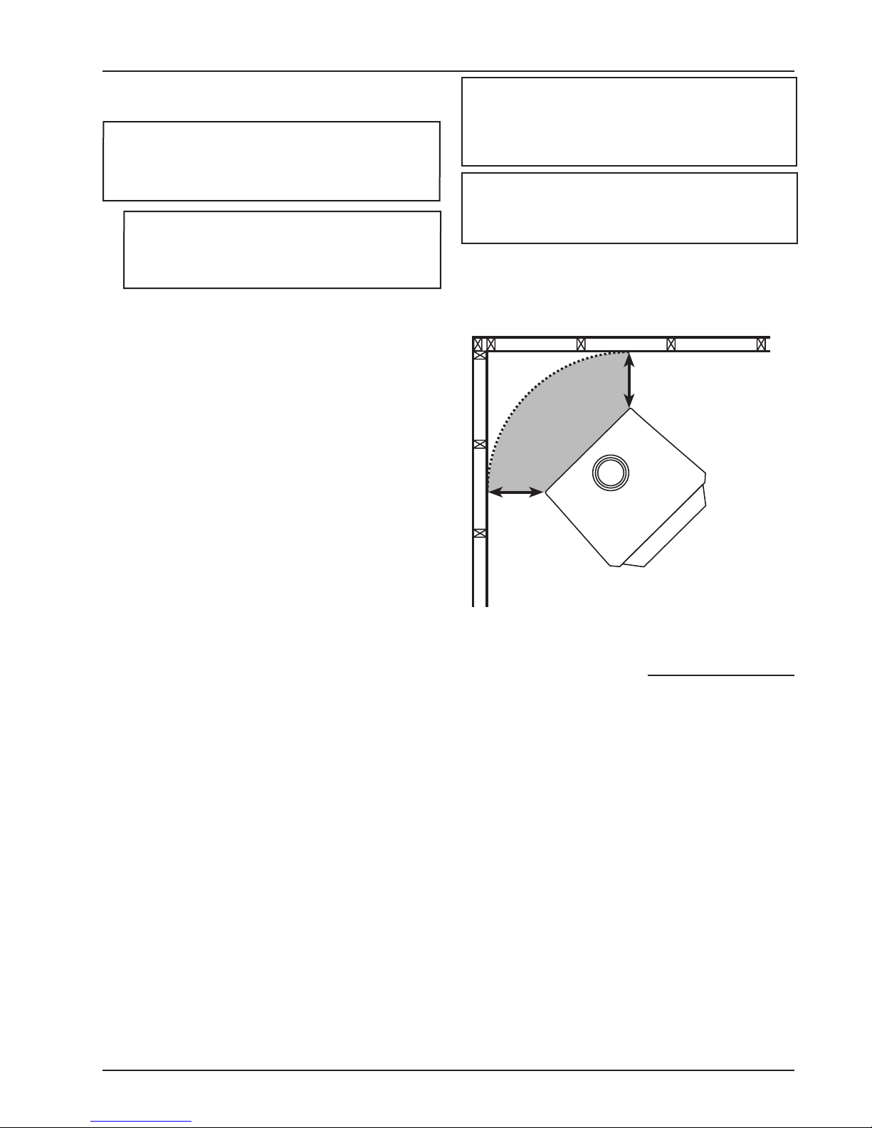
LOCATING STOVE
12"/30.5cm
12"/
30.5cm
CORNER CLEARANCES
your local building codes or fire protection
ordinances.
NOTICE: Any wall containing combustible
materials such as wooden studs, drywall and
faced with brick or stone MUST be considered
a combustible surface.
7. DO NOT install this stove in a mobile home,
manufactured home, trailer or tent – NO
EXCEPTIONS! (HUD Federal Standard:
24 CFR Ch.xx)
8. The clearances provided are minimum dimensions
set by UL 1482-2010 & ULC S627-00, tested
and applied by OMNI Test Laboratories, Inc., the
manufacturer’s testing laboratory. Installation of this
stove must comply with the latest edition of NFPA
211 (US)/CAN/CSA-B365 (CDN) for reduced clearances and/or your local building code rulings. Use
whichever minimum dimensions are the LARGEST.
Clearances listed and shown MUST be adhered to
for safe operation of this appliance. CLEARANCES
MAY NOT BE REDUCED BY ANY MEANS IN USA
OR CANADA.
9. NEVER OPERATE THIS STOVE WITHOUT THE
ASH CLEANOUT DOOR OR WITH THE ASH
DRAWER REMOVED – very dangerous operating
conditions could result.
Failure to follow these minimum clearance require-
ments may result in an unsafe installation and could
cause a fire.
10. This stove meets U.S. Test Standard: UL 1482-2010
& Canadian Standard: ULC-S627-00.
11. Always locate stove to provide a source of fresh
air into the room where the unit is installed.
Failure to do so may result in air starvation of other
fuel burning appliances and the possible development of hazardous conditions.
CAUTION: KEEP FURNISHINGS AND
OTHER COMBUSTIBLE MATERIALS AWAY
FROM THE STOVE AND OUTSIDE MINIMUM
CLEARANCES.
CAUTION: REPLACE FIREBRICKS BEFORE
FIRING WOODSTOVE. POSITION FIREBRICKS
SO NO GAPS REMAIN BETWEEN BRICKS.
Fig. 7 – Top View
Minimum Corner Clearances
from Combustible Surfaces
Continued on next page
TR001B | 20120125.0 www.vogelzang.com DEFENDER™ | Page 7
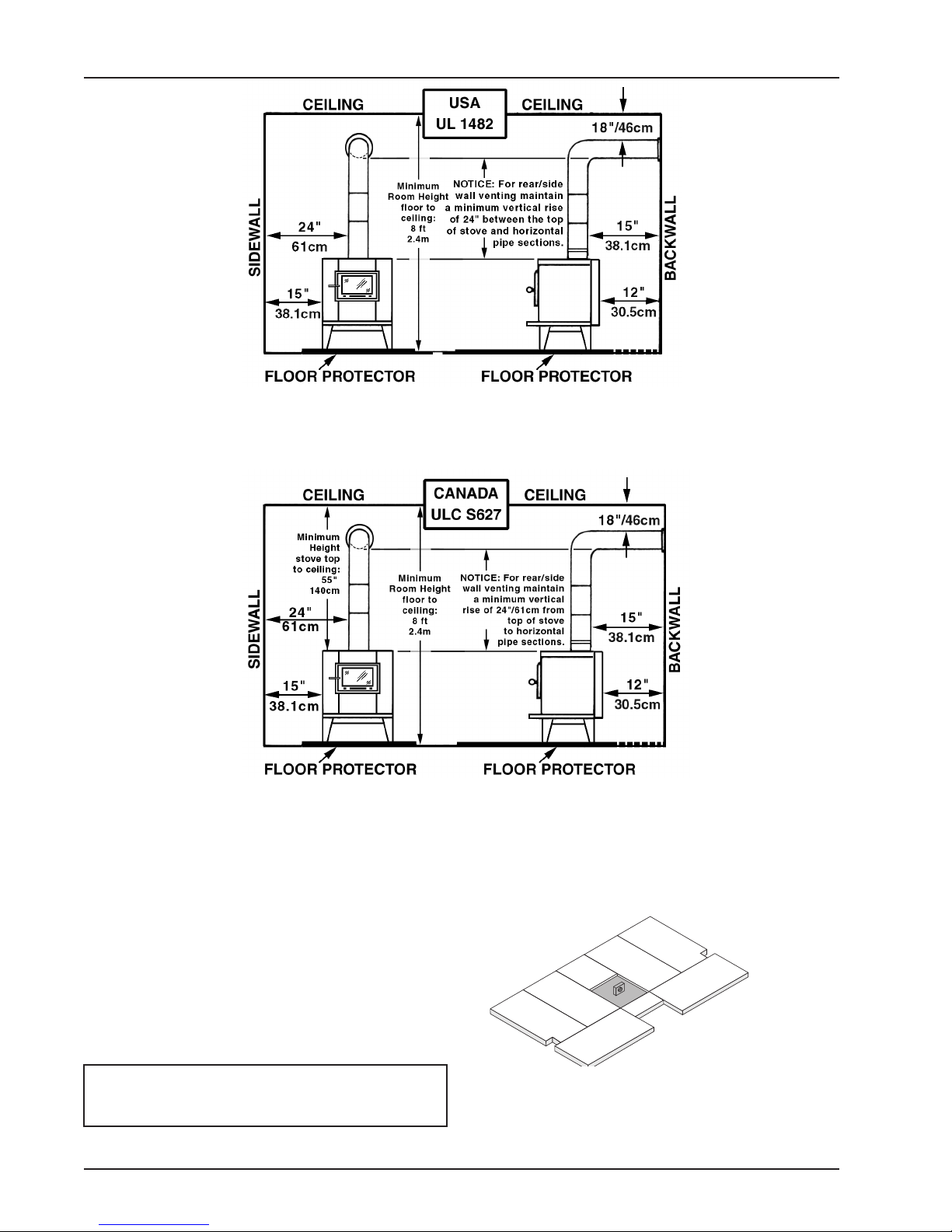
Fig. 8a – Front View
X
T
FF
Y
T
X
FF
Z
Minimum Clearance
Dimensions
from Combustible Surfaces
Fig. 8b – Side View
Minimum Clearance
Dimensions
from Combustible Surfaces
Fig. 8c – Front View
Minimum Clearance
Dimensions
from Combustible Surfaces
FIREBRICK ASSEMBLY
Firebrick extends the life of your stove and radiates
heat more evenly. Check to see that all firebricks are in
their correct positions and have not become misaligned
during shipping or assembly. If removed for ease of
locating stove, firebrick and ash dump cover must be
replaced before firing. See diagrams, fig. 9a – 9c, for
proper positioning.
CAUTION: NEVER OPERATE STOVE WITH
MISSING OR CRACKED FIRE BRICKS!
Page 8 | DEFENDER™ Vogelzang International Corp. TR001B | 20120125.0
Fig. 8d – Side View
Minimum Clearance
Dimensions
from Combustible Surfaces
Fig. 9a– Step 1, Bottom Firebrick Installation
Two (2) FF-Size; Two (2) T-Size; Two (2) X -Size;
One (1) Y-Size; One (1) Z-Size
 Loading...