

Vogelzang International BX22EL Owner's Manual
“Lit’l Sweetie” BOXWOOD STOVE
Model BX22EL Owners Manual
(save this manual for future reference)
READ ALL INSTRUCTIONS CAREFULLY BEFORE STA RTING THE
INSTALLATION OR OPERATING
DO NOT USE THIS STOVE IN A
MOBILE HOME, MANUFACTURED HOME,
TRAILER OR TENT – NO EXCEPTIONS!
THE STOVE. FAILURE TO FOLLOW
INSTRUCTIONS MAY RESULT IN
P R O P E RT Y DA M AG E , BO D I LY
INJURY, OR EVEN DEATH.
This stove meets
U.S. Test Standard:
UL 1482-2006
SAFETY INSTRUCTIONS
SAFETY NOTICE: IF THIS STOVE IS NOT PROPERLY INSTALLED, A HOUSE/BUILDING FIRE MAY
RESULT. FOR YOUR SAFETY, CONTACT LOCAL BUILDING OR FIRE OFFICIALS ABOUT PERMITS,
RESTRICTIONS, AND INSTALLATION REQUIREMENTS FOR YOUR AREA.
READ ALL INSTRUCTIONS CAREFULLY.
1. The installation of this stove must comply
with your local building code rulings. Please
observe the clearances to combustibles. Do
not place furniture or other objects within
the clearance area (see reference figures
1 & 2).
2. Do not in s tall th is stov e in a mob ile
home, manufactured home, trailer or tent
(NO EXCEPTIONS! per H U D Federal
Standard: 24 CFR Ch.XX).
3. Verify that the stove is properly installed before
firing the stove for the first time. After reading
these instructions, if you have any doubt about
your ability to complete your installation properly,
you must obtain the services of a professional
licensed installer familiar with all aspects of safe
an d corre c t inst a l lation . DO NOT use
tem p o r a r y or m a k e s h i ft c omp r o m i s es
during installation.
4. If any parts are missing or defective, please
notify the dealer or manufacturer immediately.
DO NOT OPERATE A STOVE THAT IS MISSING
ANY PARTS!
5. Do not tamper with combustion air control beyond
normal adjustment capacities.
6. Always connect this stove to a chimney and vent to
the outside. Never vent to another room or inside
a building. DO NOT CONNECT THIS UNIT TO A
CHIMNEY FLUE SERVING ANOTHER APPLIANCE.
7. DO NOT CONNECT a wood burning stove to an
aluminum Type B gas vent. This is not safe. Use approved masonry or a UL 103 HT Listed Residential
Type and Building Heating Appliance Chimney. Use
a 6” diameter chimney or larger, that is high enough to
give a good draft (See specifics in installation
instructions).
8. Be sure that your chimney is safely constructed
and in good repair. Have the chimney inspected
by the fire department or a qualified inspector. Your
insurance company should be able to recommend
a qualified inspector.
continued on next page
VGZ-003 / 2011613.0 BX22EL / Page 1
Vogelzang International Corporation
400 West 17th Street
Holland, Michigan 49423
www.vogelzang.com
Phone: 1-616-396-1911
Fax: 1-616-396-1971

SAFETY INSTRUCTIONS continued…
9. Creosote or soot may build up in the chimney connector and chimney and cause a house/building fire.
Inspect the chimney connector and chimney twice
monthly during the heating season and clean if
necessary (See Chimney Inspections, page 12).
10. In the event of a chimney fire, turn the air damper
to closed position, leave the building and CALL
THE FIRE DEPARTMENT IMMEDIATELY! Have
a clearly understood plan on how to handle a
chimney fire by contacting your local fire authority
for information on proper procedures in the event
of a chimney fire.
11. To prevent injury, do not allow anyone to use this
stove who is unfamiliar with the correct operation
of the stove.
12. D o no t o p e r a t e s t ove w h i l e u n d e r th e
influence of drugs or alcohol.
13. To prevent bur ns, alw ays wea r pr o tecti ve
clothing, l e a t h e r heart h g l o ves a n d e y e
protection, while tending the fire.
14. Ashes should not be allowed to accumulate higher
than the slide damper. Dispose of ashes in a metal
container with a tight fitting lid. Other waste shall not
be placed in this container. Keep the closed container on a noncombustible floor or on the ground,
well away from all combustible materials. Keep the
ashes in the closed container until all cinders have
thoroughly cooled. The ashes may be buried in the
ground or picked up by a refuse collector.
15. The special paints used on your stove may
give o f f s ome smoke a n d a n o dor while
they are curing during the first 12 to 15 fires. Additional smoke and odor may be emitted from the light
oils used in construction of the fire box. This should
disappear after a short period of time and not occur
again. Persons with lung conditions or owners of susceptible domestic pets (such as birds) should take
prudent preca u t i o n s. O p e n w i n dows and
doors as needed to clear smoke and/or odor.
Paint discoloration will occur if the stove is
over fired.
16. T h i s s t o ve has a p a i n t e d s u r face w h i c h
is durable but it will not stand rough handling
or abuse. When installing your stove, use care
in handling. Clean with soap and warm water
when stove is NOT hot. Do not use any acids
or scouring soap, as these solvents wear and dull
the finish.
17. W hile sto ve is in operatio n , all pers o n s,
especially young children should be alerted to the
hazards from high surface temperatures. Keep
away from a hot stove to avoid burns or clothing
ignition.
18. If small children will be in the same room as
the stove during operation, provide a sturdy barrier to keep th em at a safe dis tance
from the stove. NEVER L E AVE S M A L L
CHILDREN UNSUPERVISED when they are in the
same room as the stove.
19. Keep st o ve area c l e a r and free fr o m a l l
combustible materials, gasoline, and other flammable vapors and liquids.
20. While in operation, keep the feed door closed and
secured at all times except while tending the fire.
21. Do not over fire the stove. Over firing will occur if
the feed door is left open during operation. Such
actions can result in very dangerous operating
conditions.
22. All powe r cords and ele ctric a l applia nces
and/or assemblies must be kept outside of the
clearance dimensions shown in this manual for
combustible materials.
23. DO NOT ELEVATE FIRE! Build fire directly on the
bottom of the firebox. This stove has not been tested
with the use of grates, andirons, or other means of
elevating the fire and they should not be used.
24. For further information on using your stove
safely, ob tain a copy of th e Na tiona l Fire
Protection Association (NFPA) publication, “Using
Coal and Wood Stoves Safely” NFPA No. HS-10-
1978. The address of the NFPA is Batterymarch
Park, Quincy, MA 02269.
NOTE: A PROFESSIONAL, LICENSED HEATING AND COOLING CONTRACTOR SHOULD
BE CONSULTED IF YOU HAVE QUESTIONS
REGARDING THE INSTALLATION OF THIS
SOLID FUEL BURNING APPLIANCE.
Page 2 / BX22EL VGZ-003 / 20110613.0
ASSEMBLY INSTRUCTIONS
NOTICE: Vogelzang International Corp. grants no warranty, stated or implied, for the installation or maintenance
of your wood stove and assumes no responsibility of any incidental or consequential damages.
t o o l s r e q u i r e d
Safety Glasses
Pencil
6 foot Folding Rule or
Tape Measure
Tin Snips
Drill: Hand or Electric
1/8” dia. Drill Bit
(sheet metal screws)
Screwdrivers
(blade and cross types)
5/16” Nut Driver or Ratchet
with 5/16” Socket (for 1/4”
Hex Nuts)
11mm Nut Driver or
Ratchet with 11mm Socket
(for Stove Bolts)
(NOTE: The following items are NOT included with your stove)
Flooring Protection: 36” x 48”
as specified (see page 5)
Chimney Connection: 6”
dia. min. 24 MSG black or 26
MSG blue steel stove pipe or
elbow(s) required.
1/2” Sheet Metal Screws
m a t e r i a l s r e q u i r e d
Chimney: Existing 6” Lined Masonry Chimney or 6” Inside Dia.
listed Type HT chimney.
Furnace Cement (manufacturer
recommends Rutland Code 78
or equivalent)
CAUTION: STOVE IS HEAVY. MAKE SURE YOU
HAVE ADEQUATE HELP AND USE PROPER
LIFTING TECHNIQUES WHENEVER MOVING
STOVE.
Refer to diagram and parts lists at back of this manual.
1. Uncrate the stove and remove packing materials
and protective poly bag. (Save exterior cardboard
box for further assembly.)
2. Rem ove pa r t s fr om insid e of st ove . Par ts
include: one lid (L22-09), one damper collar (L22-
12), one feed door (L22-07), one lid lifter (L-1),
one slide damper (L22-06), seperable handle
(L22-17A), four legs (L22-01 & 01b), heat shield
(L22-14A), hardware pack (L22-HP), and S-Hook
(L22-00) from inside firebox.
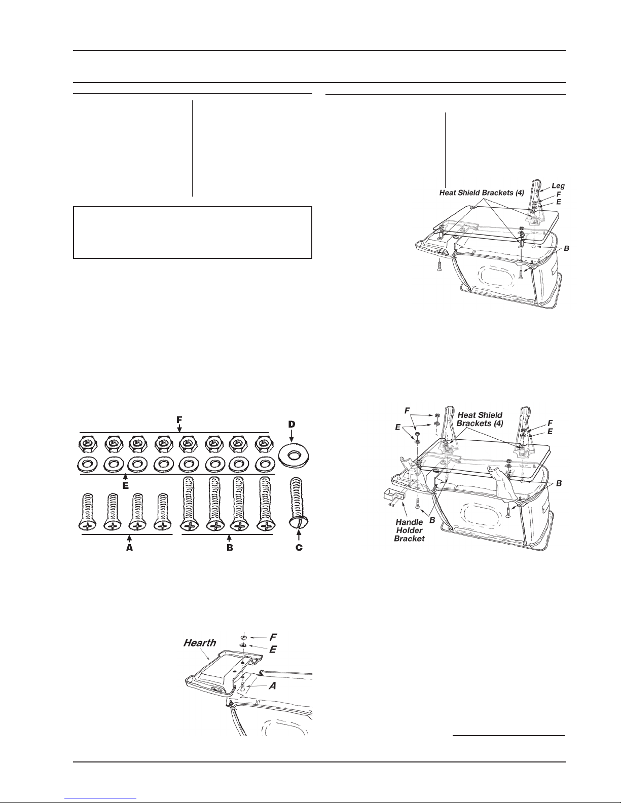
ill. C –
Rear Leg & Heat
Shield Assembly
the seperable
handle holder bracket
and this leg should be
used as one of the front legs. The long
mounting bolts (B) pass through the clearance
holes in the base of the stove, illustration C, through
the rear legs, the heat shield brackets and then are
secured with washers (E) and hex nuts (F).
6. The front legs attach in a similar method, illustration
D, with the bolts (B) passing through mounting holes
ill. D –
Front Leg &
Heat Shield
Assembly
ill. A – Hardware Pack
3. Place flattened carton on floor and carefully turn
stove over onto carton.
4. Attach hearth to bottom of stove with two short
stove bolts (A), washers (E), and hex
nuts (F).
5. The heat shield
(L22-14A), illustration C, is held to
the stove with the
mounting bolts for
the legs. Note that
one of the legs has
mounting holes for
ill. B – Hearth Assembly
VGZ-003 / 2011613.0 BX22EL / Page 3
in the hearth, through the leg, heat shield brackets
and are finally secured with washers (E) and hex
nuts (F).
7. Attach the handle holder bracket (L22-18) to the
front leg (L22-01b) with the mounting holes.
7. Carefully lift stove upright and place in desired location (see following instructions for properly locating
stove).
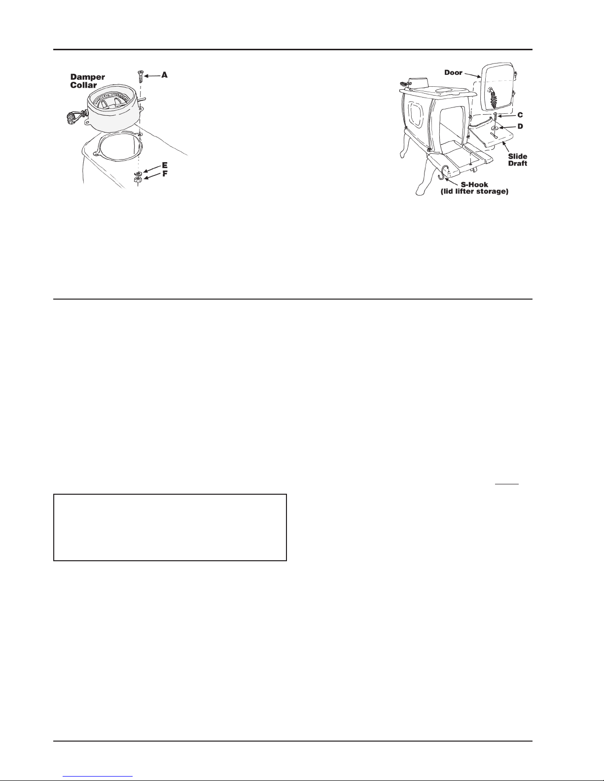
8. Attach damper collar to rear top surface of stove,
illustration E, using short stove bolts (A) flat washers
(E) and hex nuts (F).
9. Place lid in position on top of stove.
continued on next page
ASSEMBLY INSTRUCTIONS continued…
ill. E – Damper Collar
ill. F – Slide Draft,
Door & S-Hook Location
(lid lifter storage)
10. Place the slide draft into position on the hearth,
illustration F. Hold in position with round head stove
bolt (C) and large flat washer (D).
11. Lower feed door into position while aligning hinge
pins.
LOCATING STOVE
Proper clearances must be maintained for adequate air circulation. Adequate ventilation must be
provided while operating this stove.
1. The stove must be placed on solid concrete, solid
masonry, or when installed on a combustible floor,
on a listed floor protector, such as Hy-C or Imperial Model UL 3648BK, a 1/2” thick floor protector
with a R-factor of 0.84 or equivalent (see page
14 to calculate R-factors of alternative materials).
The base must extend at least 16” beyond the
front of the hearth, 8” to the sides of the stove,
and must extend under the stove pipe and 2˝
on either side if it is elbowed towards a wall (see
figure 1 and consult local building codes and fire
protection ordinances.)
CAUTION: (FIRE HAZARD) CARPETING AND
OTHER COMBUSTIBLE MATERIAL MUST NOT
COVER THE FLOOR PROTECTOR. THESE
MATERIALS MU ST REMAIN OUTSIDE OF
COMBUSTIBLE CLEARANCES, SEE FIG. 1- 2.
2. The stove must have its own flue. DO NOT
CONNECT THIS UNIT TO A CHIMNEY FLUE
SERVING OTHER APPLIANCES.
3. Af ter obs erving the clearances to combustible materials (figure 1 & 2), locate your floor
protector accordingly (figure 1) and carefully place the stove in your selected location.
Install connector pipe, elbows, and thimble as
required, utilizing either a recently cleaned and
inspected 6” masonry chimney or a 6” i.d. listed
chimney, maximum 64 square inches.
12. Place S-Hook in hole at left front corner of hearth.
Note: S-Hook is used to hang lid lifter while not
in use.
4. Use round, 6” dia., minimum 24 MSG (minimum
standard gauge) black or 26 MSG blue steel stove
pipe. DO NOT use galvanized stove pipe. Secure
pipe sections with three (3) sheet metal screws in
each stove pipe and/or elbow joint to firmly hold the
pipe sections together. DO NOT CONNECT THIS
STOVE TO ANY AIR DISTRIBUTION OR DUCT
SYSTEM.
5. R e c h e ck c l e a r a n c e s fr o m t h e st o v e ,
connector stove pipe, and corner clearances
using the location drawings (figure 1 & 2) and
your local building cod es or fir e protection
ordinances.
NOTE: Drywall faced with brick or stone must be
considered a combustible surface.
6. DO NOT INSTALL THIS STOVE IN A MOBILE HOME,
MANUFACTURED HOME, TRAILER OR TENT – NO
EXCEPTIONS! (HUD Federal Standard: 24 CFR
Ch.XX)
7. Th e c l e a r a n c e s pr o v i d e d are m i n i m u m
dimensions determined by NFPA. Installation of
this stove must comply with the latest edition of
NFPA 211 for reduced clearances and/or your local building code rulings. Use whichever minimum
dimensions are LARGEST.
Failure to follow these minimum clear-
ance requirements may result in an unsafe
installation and could cause a fire.
Page 4 / BX22EL VGZ-003 / 20110613.0
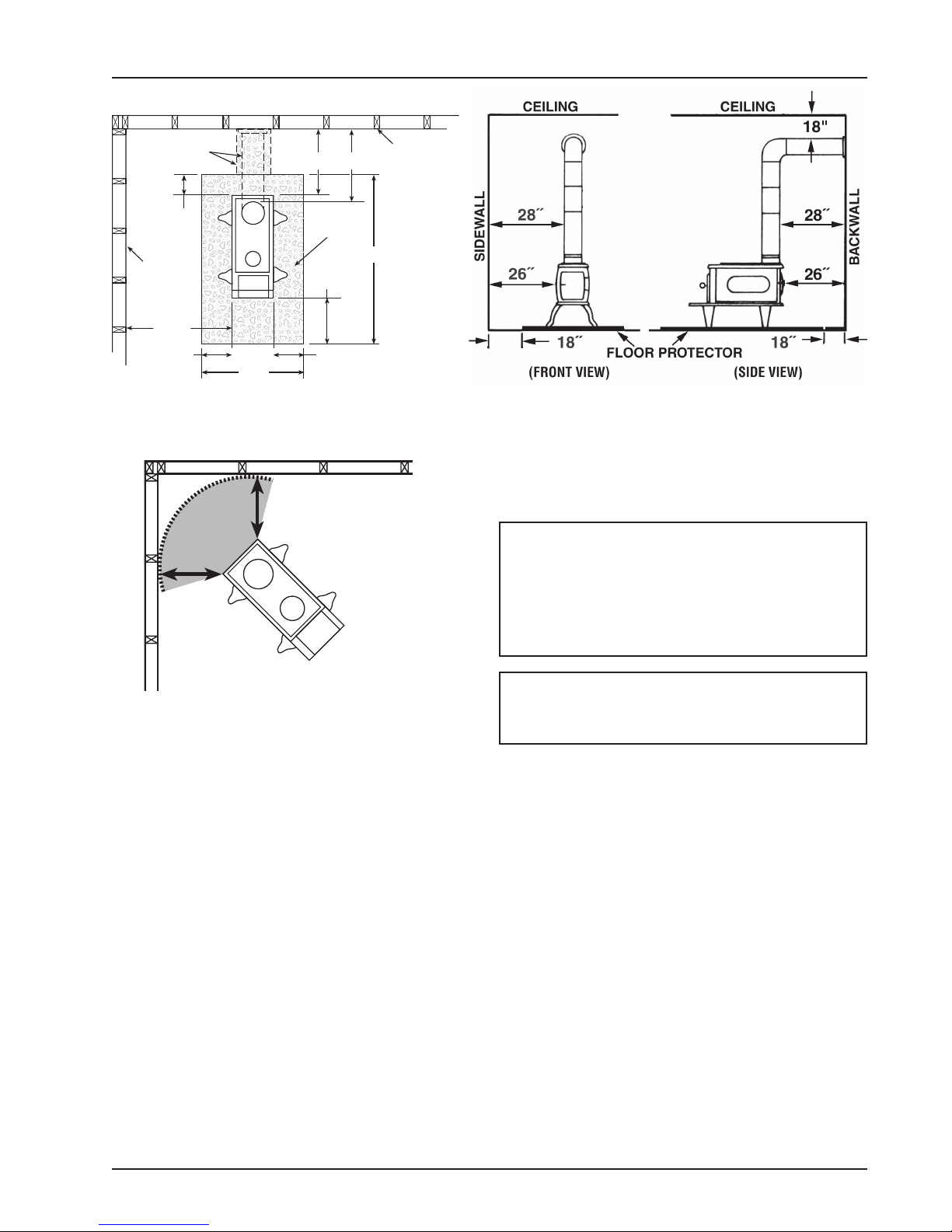
24.5"
24.5"
CORNER CLEARANCES
LOCATING STOVE continued…
COMBUSTIBLE
CONSTRUCTION IN
ACCORDANCE WITH
NFPA 211
FLOOR
PROTECTOR
DASHED LINE SHOW S
HORIZONTAL CHIMNEY
CONNECTOR AND
ADDITIONAL FLOOR
PROTECTION REQUIRED
BACKWALL
27"
(TOP VIEW)
8"
8"
8"
26" 28"
26"
48"
16"
SIDEWALL
NON-COMBUSTIBLE
CONSTRUCTION IN
ACCORDANCE WITH
NFPA 211
Fig. 1 – Minimum Clearance Dimensions from Combustible Surfaces
MINIMUM CLEARANCES
TO COMBUSTIBLE SURFACES
Fig. 2 – Top View
Minimum Corner Clearances from
Combustible Surfaces
VGZ-003 / 2011613.0 BX22EL / Page 5
Unit to Sidewall ........................ 26 inches
Unit to Backwall ........................ 26 inches
Unit Corner to Wall ..................24.5 inches
Pipe Connector to Backwall .......... 28 inches
Pipe Connector to Ceiling ............ 18 inches
CAUTION: KEEP FURNISHINGS AND OTHER
COMBUSTIBLE MATERIALS AWAY FROM THE
STOVE.
 Loading...