

Vogelzang 2500 User Manual
NORSEMAN
WARM AiR FuRNAcE
Models 1500/2500 Owners Manual
(save this manual for future reference)
™
SOlid FuEl
READ ALL INSTRUCTIONS CAREFULLY
BEFORE INSTALLING OR OPERATING
THIS FURNACE.
FAILURE TO FOLLOW INSTRUCTIONS
MAY RESULT IN PROPERTY DAMAGE,
BODILY INJURY, OR EVEN DEATH.
REFER TO MARKINGS ON
FURNACE LABELS FOR
ADDITIONAL INFORMATION.
VGZ-018 / 051809.0 NORSEMAN™ 1500/2500 FURNACE / Page 1
NOTE: INSTALLATION MUST BE
COMPLETED BY A QUALIFIED
HEATING EQUIPMENT INSTALLER!
DO NOT USE THIS FURNACE IN A
MOBILE HOME, MANUFACTURED HOME,
TENT OR TRAILER – NO EXCEPTIONS!
Vogelzang International Corporation
400 West 17th Street
Holland, Michigan 49423
www.vogelzang.com
Phone: 1-616-396-1911
Fax: 1-616-396-1971
This furnace meets
U.S. Test Standard:
UL 391-06
SAFETY INSTRUCTIONS
SAFETY NOTICE: IF THIS FURNACE IS NOT PROPERLY INSTALLED, A HOUSE/BUILDING FIRE
MAY RESULT. FOR YOUR SAFETY, CONTACT LOCAL BUILDING OR FIRE OFFICIALS ABOUT
PERMITS, RESTRICTIONS, AND INSTALLATION REQUIREMENTS FOR YOUR AREA.
READ ALL INSTRUCTIONS CAREFULLY.
Refer to instru ctio n panel s, ca utio n and
warnin g plates on furnac e for ad dit iona l
information.
1. This furnace is designed to burn coal or wood fuels
only and is for INDOOR INSTALLATION ONLY.
DANGER: RISK OF FIRE OR EXPLOSION. Do
not burn garbage, gasoline, drain oil or other
flammable liquids.
2. DO NOT attempt to retrofit this unit with any type
of water coil or water jacket.
3. The installation of this furnace MUST comply
with your local building code rulings. Please
observe the clearances to combustibles (see
reference figures 1–3). Do not place furniture
or other objects within the clearance area.
4. Verify that the furnace is properly installed before firing for the first time. Obtain the services
of a professional licensed installer familiar with
all aspects of safe and correct installation. DO
NOT use temporary or makeshift compromises
during installation.
5. WARNING: Risk of Fire. DO NOT store fuel,
flammable liquids or other combustible materials too close to the unit. Refer to the certification
label on back of unit and reference clearance
instructions in this manual.
6. DO NOT INSTALL THIS FURNACE IN A MO-
BILE HOME, MANUFACTURED HOME, TENT
OR TRAILER – NO EXCEPTIONS! (HUD Fed-
eral Standard: 24 CFR Ch.XX)
7. If any parts are missing or defective, please notify the manufacturer or dealer immediately. DO
NOT OPERATE A STOVE THAT IS MISSING
ANY PARTS
8. Always connect this furnace to a chimney and
vent to the outside. NEVER vent to another
room or inside a building. DO NOT CONNECT
THIS UNIT TO A CHIMNEY FLUE SERVING
ANOTHER APPLIANCE.
9. DO NOT CONNECT this furnace to an aluminum
Type B gas vent. This is not safe. Use approved
masonry or a UL 103 HT Listed Residential
Type and Building Heating Appliance Chimney.
Use a 6” diameter chimney or larger, that is high
enough to provide required draft. (See specifics in
installation instructions).
WARNING: Risk of Fire. Do not operate with flue draft
exceeding
10. Inspect flue pipes, pipe joints, and flue pipe seals
regularly to ensure that smoke and flue gases are
not drawn into, and circulated by the air circulation
system.
11. Cleaning of this furnace, is especially important at
the end of the heating season. Accumulated ash
attracts moisture and may cause corrosion during
the summer months.
12. B e s u re t h a t yo u r c h i m ne y is s afe l y
constructed and in good repair. Have the chimney
inspected by the fire department or a qualified
inspector. Your insurance company may be able to
recommend a qualified inspector.
13. Creosote or soot may build up in the chimney
connector and/or chimney and cause a house,
building or chimney fire. Inspect the chimney
connector and chimney twice monthly during the
heating season and clean if necessary. (See Chimney Maintenance, page 18).
14. To prevent injury, do not allow anyone to use this
furnace who is unfamiliar with the correct operation
of the furnace.
15. D o n ot operate furnace while under the
influence of drugs or alcohol.
16. Ashes should not be allowed to accumulate higher
than the ash pan. Dispose of ashes in a metal container with a tight fitting lid. Keep the closed container on a noncombustible floor or on the ground,
well away from all combustible materials. Keep the
ashes in the closed container until all cinders have
thoroughly cooled. The ashes may be buried in the
ground or picked up by a refuse collector.
17. Build several small fires on first use. This will help
to “season” the cast iron parts and avoid cracking.
Allow furnace to cool between firings.
18. The special paints used on your furnace may
give off some smoke and an odor while they
are curing during the first 12 to 15 fires.
Additional smoke and odor may be emitted from
the light oils used in construction of the fire box.
This should disappear after a short period of time
continued on next page
Page 2 / NORSEMAN™ 1500/2500 FURNACE VGZ-018 / 051809.0
SAFETY INSTRUCTIONS continued…
and not occur again. Persons with lung conditions
or owners of susceptible domestic pets (such as
birds) should take prudent precautions. Open windows and doors as needed to clear smoke and/or
odor. Paint discoloration will occur if the furnace
is over fired.
19. This fur nace has a painted surface which is
durable but it will not stand rough handling or
abuse. When installing your furnace, use care
in handling. Clean with soap and warm water
when furnace is not hot. Do not use any acids
or sco uring so ap, as these we ar and dul l
the finish.
20. CAUTION: HOT SURFACES. Keep children
away. Do not touch while in operation. While in
operation, all persons, especially young children,
should be alerted to the hazards from high surface
temperatures and should be kept away to avoid
burns or clothing ignition.
21. If small children will be in the same room as the
furnace during operation, provide a sturdy barrier
to keep them at a safe distance from the stove.
NEVER LEAVE SMALL CHILDREN UNSUPERVISED when they are in the same room as the
stove.
22. Keep furnace area clear and free from all combustible materials, gasoline, and other flammable
vapors and liquids.
23. To prevent burns, always wear protective clothing,
leather hearth gloves and eye protection while
tending the fire.
24. WARNING: Risk of Fire. While in operation, keep
the feed door and ash door closed at all times except while tending the fire.
25. WARNING: Risk of Fire. Do not over fire the furnace. Over firing will happen if the feed door or ash
door is left open during operation. Over firing may
occur if flue draft is too great. Do not operate with
a flue draft exceeding 0.05˝ water column (0.1 Pa).
Such actions can result in very dangerous operating
conditions and risk of structure fire.
26. WARNING: Risk of Fire. Inspect and clean flues
and chimney regularly. See Chimney Maintenance
section (pg 18).
27. For fu r t her informa tion on us ing yo ur furnace safely, obtain a copy of the National Fire
Protection Association (NFPA) publication, Using
Coal and Wood Stoves Safely, NFPA No. HS-10-
1978. The address of the NFPA is Batterymarch
Park, Quincy, MA 02269.
NOTE: INSTALLATION SHOULD BE COMPLETED BY A PROFESSIONAL, LICENSED
HEATING AND COOLING CONTRACTOR ONLY.
VGZ-018 / 051809.0 NORSEMAN™ 1500/2500 FURNACE / Page 3

TABLE OF CONTENTS
SAFETY PRECAUTIONS ..................................................................................... 2
FURNACE DESCRIPTION & INSTALLATION OPTIONS .................................... 5
LOCATING THE FURNACE ................................................................................. 6
TOOLS AND MATERIALS REQUIRED FOR INSTALLATION ............................ 7
ASSEMBLY INSTRUCTIONS ............................................................................... 8
FURNACE INSTALLATION .................................................................................. 9
WIRING DIAGRAM ............................................................................................. 10
FURNACE DIMENSIONS ................................................................................... 11
CHIMNEY CONNECTIONS ................................................................................ 12
CONNECTOR PIPE INSTALLATION ................................................................. 13
OPERATING INSTRUCTIONS ........................................................................... 15
COAL BURNING TIPS ........................................................................................ 16
BLOWER LIMIT CONTROL SETTINGS ............................................................ 17
AIR FILTER INSTRUCTIONS ............................................................................. 17
POWER FAILURE INSTRUCTIONS................................................................... 17
BLOWER FAN AND MOTOR CARE .................................................................. 17
CHIMNEY MAINTENANCE ................................................................................ 18
END OF SEASON (ASH REMOVAL) MAINTENANCE ..................................... 18
INSTALLATION ARRANGEMENT DIAGRAMS ......................................... 19 – 22
PARTS NORSEMAN™ 1500 ...................................................................... 24 – 25
PARTS NORSEMAN™ 2500 ...................................................................... 26 – 27
Page 4 / NORSEMAN™ 1500/2500 FURNACE VGZ-018 / 051809.0

FURNACE DESCRIPTION & INSTALLATION OPTIONS
Your NORSEMAN™ Solid Fuel Warm Air Furnace
is designed to provide supplemental or central heating
for your home. This solid fuel furnace may be installed
in conjunction with a central furnace that is in proper
operating condition and meets all national and/or
local building codes, safety standards, required controls
and has been installed in accordance with appropriate
standards of the National Fire Protection Association
and in accordance with the clearances specified on the
furnace nameplate.
Installation of NORSEMAN™ Furnaces must
be accomplished by a qualified heating contractor
(one who is engaged in, and is responsible for, or is
thoroughly familiar with the installation and operation
of gas, oil, and solid fuel burning heating appliances,
who is experienced in such work and familiar with all
the requirements of the authority having jurisdiction.)
The installation shall be in strict accordance with the
manufacturer’s installation instructions furnished with
the solid fuel furnace.
The chimney connector of the furnace is to be
installed to provide clearances to combustible materials not less than specified in the individual classifications and marked on the furnace. The chimney must
be suitable for use with residential type or building
heating appliances which burn solid fuel. DO NOT
CONNECT THIS UNIT TO A CH IMN EY FLUE
SERVING ANOTHER APPLIANCE.
The furnace is designed to operate in either parallel air flow arrangement with a central
furnace as shown in the diagrams or as a stand alone
central furnace. (See connection option diagrams,
figures 17 – 23, on pages 19 – 22.)
CENTRAL FURNACE INSTALLATION
As a ce n t r al furnace, t h e u nit functi o n s
independently of any other heating system. The
blower(s) will come on when the plenum temperature
reaches the setting on the blower control.
ate simultaneously. For the most efficient use of your
NORSEMAN™ Warm Air Furnace, it is recommended
that it be fired as much as possible in order to reduce
the demand on the central heating system. An optional
forced draft kit (Model DK-50) is available that operates
from a wall thermostat. When the temperature falls
below the setting on the wall thermostat, the forced
draft will come on.
T h e w ar m a i r s u p p l y ou t l et o f t h e
NORSEMAN™ Furnace MUST NOT BE CON-
NECTED TO THE COLD AIR RETURN of th e
central heating furnace because of the possibility of
overheating components of the central furnace and
causing it to operate outside the specifications for which
it was designed.
The operating external static pressure and air
temperature rise of existing furnace must be within ratings marked on the central furnace nameplate. Test for
proper operation of the central furnace after installation
of the supplementary furnace.
FURNACE SIZING
When using a NORSEMAN™ furnace in parallel
with an existing central heating furnace it is important
to select a size that is compatible with the existing unit.
For best results, the BTU rating of the NORSEMAN™
furnace should be equal to or less than the rating of
your existing furnace.
NOTICE: Installing an add-on furnace that
exceeds the listed BTU rating of the existing heating appliance may create an unsafe operating
condition.
Seek the services of a professional HVAC contractor if you have questions regarding your duct supply
system.
PARALLEL INSTALLATION
When the NORSEMAN™ Warm Air Furnace is installed in parallel with an existing central heating furnace, it is designed to turn on the
central unit blower whenever the Warm Air Furnace blower turns on. The NORSEMAN™ blower
will only come on when the temperature in the
plenum has reached the setting on the blower
control. This insures there will be sufficient warm air
in the system to provide for efficient operation. When
the central system thermostat calls for heat, the central
system will operate by igniting the burner and turning
on the blower. It is possible that both systems will oper-
VGZ-018 / 051809.0 NORSEMAN™ 1500/2500 FURNACE / Page 5
LOCATING FURNACE
NOTICE: Installation of this furnace must be done
by a qualified heating equipment installer.
C A U T I O N : F U R N AC E U N I T S A R E
HEAVY - APPROXIMATELY 450-550 LBS.
MAKE SURE YOU HAVE PROPER EQUIPMENT AND OR SUFFICIENT MANPOWER TO
PREVENT INJURY WHEN DELIVERING AND
LOCATING FURNACE UNITS.
1. The furnace must be placed on solid concrete or
masonry floor. NOTE: To reduce weight during in-
stallation remove parts from inside the firebox.
Additional weight reductions can be obtained
by removing the fire brick. Make note of position
so they are returned to the same positions.
CAUTION: DO NOT OPERATE THIS APPLIANCE
WITH CRACKED OR MISSING FIREBRICKS.
2. The furnace should be located in the same
room as the central heating system, as close as
possible but no closer than 6˝ to the central system. (See figures 16 – 23). Make sure to allow for
maintenance clearances of the central heating
system.
3. Obser ve the clearances to c o m bustible
materials as listed and shown in figures 1, 2 & 3.
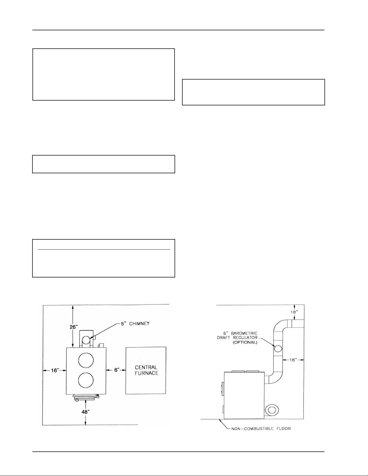
Minimum Clearances to Combustible Surfaces
Front: 48 in. Side: 16 in. Back: 26 in.
Chimney Connectors: 18 in. Plenum to wall-
studs, joists or finished wall or ceiling: 2 in.
4. The furnace MUST have its own flue. DO NOT
CONNECT THIS UNIT TO A CHIMNEY FLUE
SERVING OTHER APPLIANCES.
5. Install furnace pipe, elbows, and thimble as
required, utilizing either a recently cleaned and
inspected 6˝ masonry chimney or a 6˝ i.d. listed UL
103 HT chimney. NOTE: A barometric draft regulator may be necessary if the chimney draft is found
to be excessive.
WARNING: RISK OF FIRE. DO NOT OPERATE
WITH FLUE DRAFT EXCEEDING 0.05˝ WATER
COLUMN (0.1 Pa).
6. Use 6˝ diameter minimum 24 MSG black or 26 MSG
blue steel furnace pipe to connect to the chimney.
DO NOT use galvanized furnace pipe. Secure pipe
sections with three (3) sheet metal screws in each
furnace pipe and/or elbow joint to firmly hold the
pipe sections together.
7. Re c h eck c l e aran c e s f rom t h e f ur n a ce,
connector furnace pipe, and corner clearances using the illustrations in figures 1 – 3 and
your local bui lding codes or fire protection
ordinances.
NOTE: A studded wall faced with brick or stone
must be considered a combustible surface.
8. DO NOT INSTALL THIS FURNACE IN A MOBILE
HOME, MANUFACTURED HOME, TENT OR TRAILER.
NO EXCEPTIONS! (HUD Federal Standard: 24 CFR Ch.XX)
9. The clearances provided are minimum dimensions determined by the manufacturer’s testing
facility in accordance with U.S. Test Standard
UL 391-06. Installation of this fur nace must
comply with the latest edition of NFPA 211 for reduced clearances and/or your local building code
rulings (use whichever minimum dimensions are
LARGEST).
Fig. 1 – TOP VIEW
Minimum Clearances from Combustible Surfaces
Minimum Clearances from Combustible Surfaces
Fig. 2 – SIDE VIEW
Page 6 / NORSEMAN™ 1500/2500 FURNACE VGZ-018 / 051809.0
LOCATING FURNACE continued…
WARNING: RISK OF FIRE
• DO NOT STORE FUEL, FLAMMABLE LIQUIDS OR OTHER
CO MBU STI BLE MATE RIALS
TOO CLOSE TO THE UNIT.
• Keep furni shi ngs and
OTHER COMBUSTIBLE MATERIALS OUTSIDE OF CLEARANCE
DIMEN S I ONS MAR K E D ON
FURNACE.
• Before firing furnace,
SLIDE FIREBRICKS TOWARDS
REAR SO NO GAPS REMAIN
BETWEEN BRICKS. DO NOT
OPERATE FURNAC E WI T H
CRACKED OR MISSING FIRE
BRICKS.
Fig. 3 – Minimum Plenum Clearances from Combustible Materials
TOOLS & MATERIALS REQUIRED FOR ASSEMBLY
AND INSTALLATION
TOOLS REQUIRED
Safety Glasses
Gloves
Pencil
6 ft. Tape Measure
Tin Snips
Sabre Saw
Drill
1/8” dia. Drill Bit (for sheet metal screws)
Screwdrivers (Phillips & slotted)
6mm Socket with Driver
10mm Socket with Driver
10mm open end box wrench
7/16” box wrench
NOTE: The following items are NOT included with
your furnace:
Chimney Connection:
6” da. minimum 24 MSG black or 26 MSG blue steel
straight furnace pipe, elbow(s), collar and thimble (as
required).
6˝ Barometric Draft Regulator (optional)
8˝ Round Butterfly Anti-Backdraft Damper
(2 required – for parallel installation only)
Plenum & Duct Work with min. temperature rating of
250° F (as required).
Chimney: Existi ng 6” Lined Masonry Ch imney
or 6” Inside Dia. Listed Type HT chimney.
1/2” Sheet Metal Screws
Electrical Wiring: 16 ga. AWG copper with 90° C min.
DO NOT use aluminum wire or connectors.
1/2˝ Conduit & Connectors
Furnace Cement (manufacturer recommends Rutland
Code 78 or equivalent)
MATERIALS REQUIRED
VGZ-018 / 051809.0 NORSEMAN™ 1500/2500 FURNACE / Page 7
ASSEMBLY INSTRUCTIONS
Your N ORS E M AN™ W a r m A i r F ur n a ce
requires the following items to be assembled or installed
by the furnace installer:
Feed Door Pull Handle/Thermostat Assembly
Feed Door Locking Handle
Blower(s) and Blower Control
Electrical Connections
1. Remove all parts from inside the furnace and
inspect for damage, including the firebrick as
some breakage could occur during shipment.
Do not operate furnace with broken or miss-
ing fire box bricks. Replace damaged bricks
before operating furnace.
2. Assemble the feed door pull handle as shown in
figure 4. Install thermostat assembly and cover as
shown.
3. Align thermostat control knob with flat on thermostat
control shaft and press onto shaft (figure 4).
4. Attach feed door locking handle as shown in
figure 5 with screws and nuts provided.
Note: Slotted holes are for adjustment of handle.
Adjust handle until pressure is required to lock feed
door.
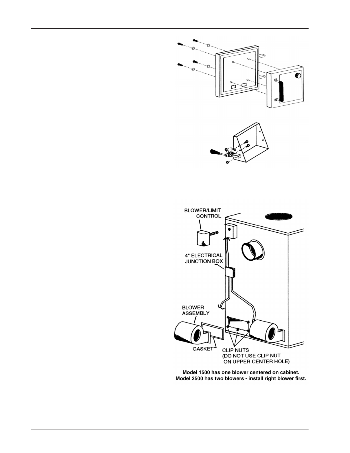
5. Install Blower/Limit Control on rear of furnace
cabinet as shown in figure 6 using three (3) sheet
metal screws.
6. Remove blower(s) from carton(s). Attach the flex-
ible conduit/wire assembly to the blower(s) before
mounting.
7. Remove junction box cover and take out the mount-
ing hardware package. Position clip nuts to furnace
housing around blower opening as shown in figure
6. On Model #2500, install the right (when facing
rear of furnace) blower first. Install the blower(s)
with gasket using 1/4-20 x 3/4˝ bolts.
8. Secure the 4 inch square electrical junction box to
the black bracket on the rear of the stove using two
(2) sheet metal screws.
9. Wire blower according to the wiring diagram shown
in figure 7/8. On model 2500, wire right side blower
first (see figure 7). Replace junction box cover when
complete. Use 16 ga. AWG rated for 90° C min.
10. Check operation of shaker grates with grate handle
before loading fuel in furnace.
Fig. 4 – Door/Handle/Thermostat Assembly
Fig. 5 – Feed Door Handle Assembly
Fig. 6 – Blower Assembly
Page 8 / NORSEMAN™ 1500/2500 FURNACE VGZ-018 / 051809.0

FURNACE INSTALLATION
NOTE: INSTALLATION MUST BE MADE BY A
QUALIFIED HEATING EQUIPMENT INSTALLER
(one who is engaged in, and is responsible for, or is
thoroughly familiar with the installation and operation
of gas, oil, and solid fuel burning heating appliances,
who is experienced in such work and familiar with all the
building requirements and/or fire codes of the authority
having local jurisdiction.)
This is a furnace, not a stove. Heated air must be
directed away from the furnace or it will not operate
properly.
1. Th e i nst a l l ati o n i s to b e c o mple t e d i n
acco r dance with Nationa l Fire Prote c t ion
Association (NFPA) installation standards No.
89M, 90B, 211, 70 (National Electrical Code) and
Uniform Mechanical Code 913, 6-4 in states where
applicable (where code offers making flue pipe
connections into an existing chimney with other
fuel burning appliances).
2. Wood /coal burning appliance s need air for
combustion and circulation to the house.
Provision must be made to provide make up
ai r so as not to st arve th e central heat ing
system of combustion air. Have the local regu-
lating authority determine that make up air
supply is adequate. Reference NFPA standards
No. 30 & 54, Code for Installation of Gas and Oil
Equipment.
3. H a ve t he l o cal r e gul a t ing a uth o r ity o r
qua l ifie d expert inspe ct all chimneys and
ins talla tions for adequa te vent ing and fo r
compli anc e with stan dar d local co des and
regulations regarding installation of wood/coal
burning appliances. (Also see Pipe Installation on
following pages.)
4. Po s i t i on the furnace according t o c l e a r -
ances shown in figures 1–3 and to maintain
chimney connections as short as possible. Avoid
unnecessary turns and installation of devices that
would create excessive resistance to the flow of
flue gases.
5. Make flue pipe connections to the chimney
with 6” dia. minimum 24 MSG black or 26 MSG
blue steel pipe and elbows (not included with
furnace) maintaining proper clearances. DO
NOT use galvanized pipe for chimney connec-
tions. Seal the flue pipe in the chimney with
furnace cement. (Chimney connections must be
securely supported and connections fastened with
3 sheet metal screws at each joint.)
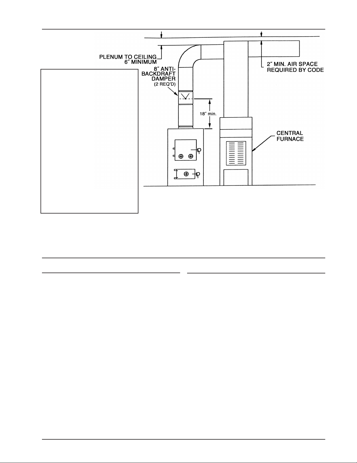
6. For parallel installations, install (two) 8˝ anti-backdraft butterfly dampers (Vogelzang Model AD-8, not
included with the furnace) in the heat (duct) pipes
a minimum of 18 inches above the furnace
plenum. Anti-backdraft butterfly dampers may be
obtained where you purchased your appliance or
from a local HVAC distributor.
7. Install 8˝ diameter 26-gauge heat (duct) pipe
and connectors (not included with furnace) to
make connection to the plenum of the central
heating system. The heat pipe, plenum, and
connections must be constructed of metal with
a minimum temperature rating of 250° F. If
cen tral air co nditi onin g is in stall ed in the
plenum, i n s t a l l h e a t p ip e above t h e a i r
condi t i o n i n g u n i t . S e c u r e th e h e at p i p e
connec tion with su ppor t s and sheet meta l
screws.
8. Make ele ctric al sup ply con nect ions in th e
ele ctri cal jun ction box and con nect powe r
supply wires to designated wires using wire nuts
(see wiring diagram figure 7 & 8). The power cord
supplied may be used for installation if local codes
and regulations permit. If not permitted, power
supply wiring must be minimum of 16 ga. AWG
copper and rated for 90° Centigrade installed in a
metal cable or conduit. Power connections should
be made by a qualified installer to comply with
NFPA Standard No. 70 and all local codes and
regulations.
VGZ-018 / 051809.0 NORSEMAN™ 1500/2500 FURNACE / Page 9
 Loading...