

Page 1
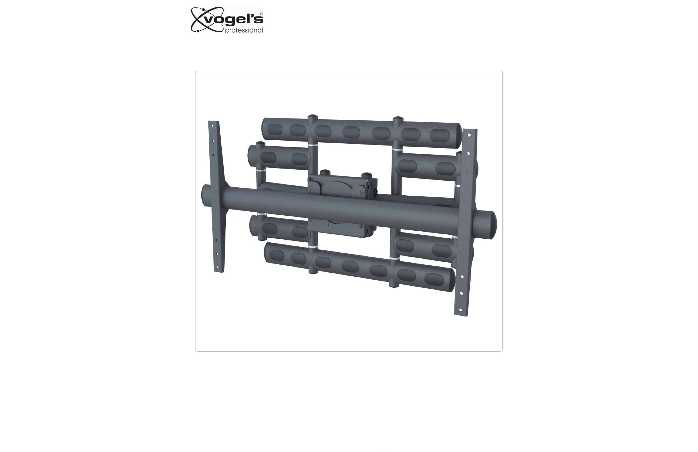
PFW6855
Installation Guide
Installationsanleitung, Guía de Instalacíon, Guida de Installazione, Guide d’Installation, Installatie gids
9531-060-Z00-01
www.vogels.com
Page 2
Refer to
Step:
PFW6855
Installation Guide
Installationsanleitung, Guía de Instalacíon, Guida de Installazione, Guide d’Installation, Installatie gids
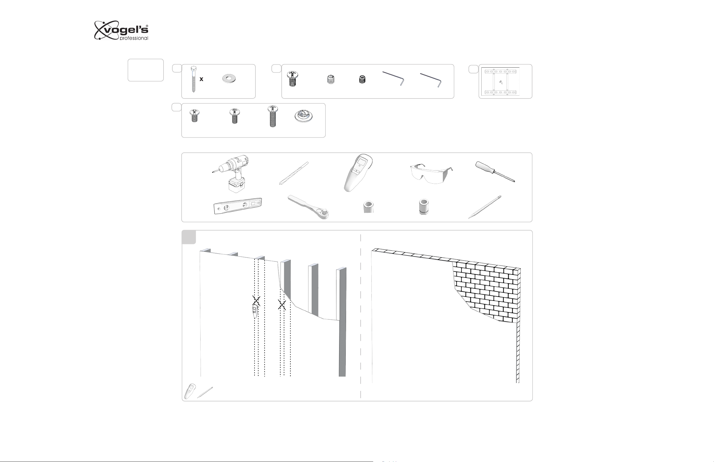
Included components
3
x6
x6 x2
10
x4
x2
x1
x1
3
x1
5/16” x 3”
10
5/16” M6 x 12mm M8 x 10mm
x4 x4 x4
M8 x 16mm M8 x 20mm M8 x 30mm
Required for installation
1
1
1/4” / 6.5mm
x8
M5 x 6mm
Stud Finder
M10 1/2 ”/13mm
5/32”
2.5mm
Drill Template
Note: It is extremely important that this installation be
carried out by well qualified installation personal and the
mounting surface capable of supported the weight of the
display mount together through out the articulating range of
the PFW6855 series mount.
9531-060-Z00-01
www.vogels.com
Page 3
PFW6855
Installation Guide
Installationsanleitung, Guía de Instalacíon, Guida de Installazione, Guide d’Installation, Installatie gids
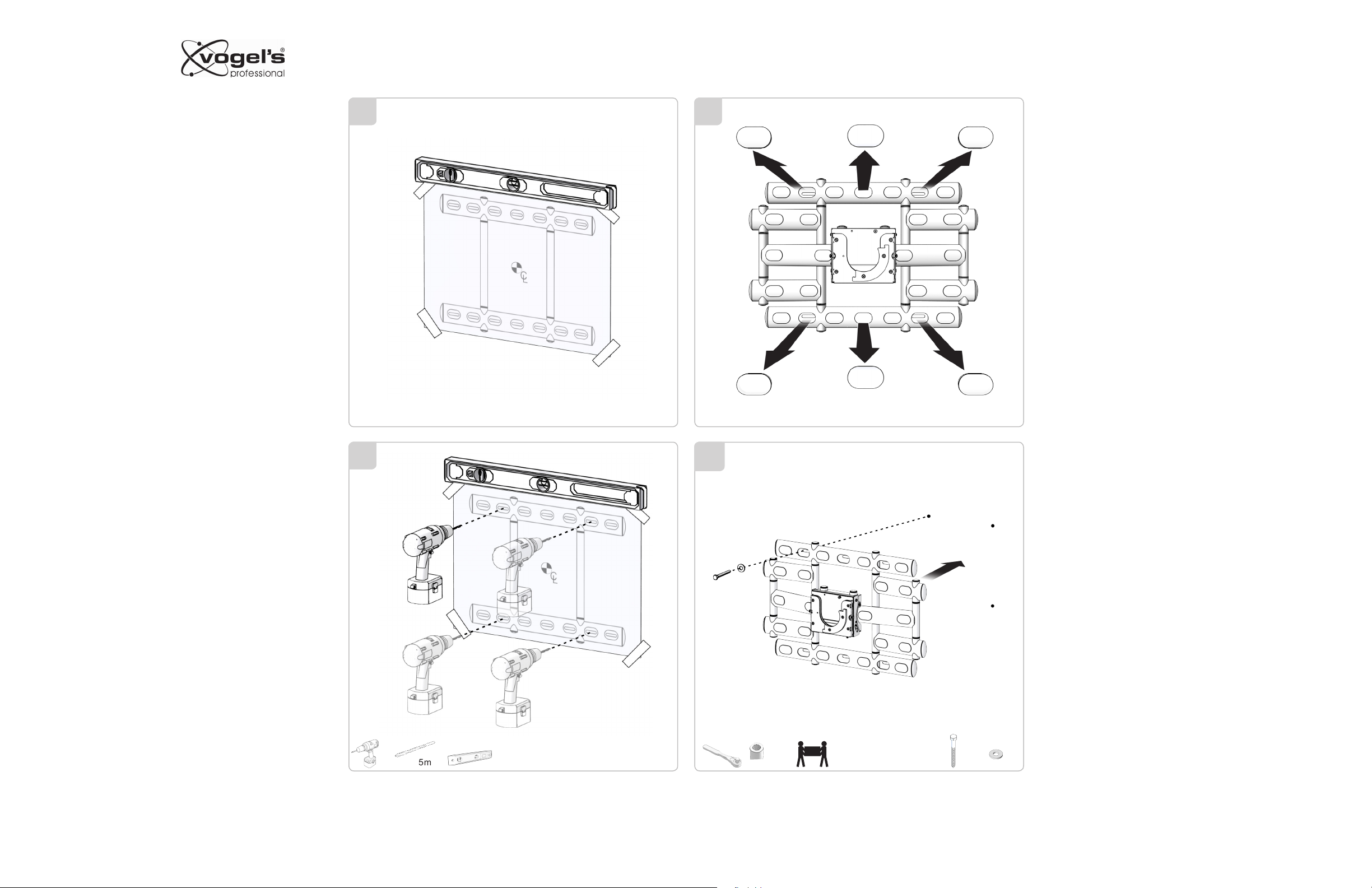
1
3
2
4
2 3
Take the mounting template supplied insure the template
is centered and level at the desired height on the mounting
surface. Mark the mounting hole (six recommended) three
on top and three on bottom.
Note: drill mounting pilot holes to a proper depth to insure
the lag or wedge anchor bolts are fully engaged into the
hole.
3
5
1/4” / 6.5mm
4
6A
4 5
1/2 ”/13 mm
x1
With minimum two people place the PFW6855 wall plate
assembly and secure to the wall using the top center hole of
the wall plate.
With a spirit level place on top of the wall plate level the
mounts than secure the remaining bolts through the wall
plate to the wall.
x1
9531-060-Z00-01
www.vogels.com
Page 4

6
PFW6855
Installation Guide
Installationsanleitung, Guía de Instalacíon, Guida de Installazione, Guide d’Installation, Installatie gids
6B 7
1
2
7
Remove the two security screws from the right and left side
of the mounting bracket crossbar and slide the two mounting
brackets inside the left and right side security screw hole
and reinstall the two security screws.
Remove the two security screws from the right and left side
of the mounting bracket crossbar and slide the two mounting
brackets inside the left and right side security screw hole
and reinstall the two security screws.
8 9
3
8
1/2 ”/13mm
x4
x4
9A
4
Make sure to keep space between
the bracket and display.
9531-060-Z00-01
www.vogels.com
5/32”
x4
M8 x 16 mm
or
x4
M8 x 20 mm
or
M8 x 30 mm
x4
Page 5

PFW6855
C
Installation Guide
Installationsanleitung, Guía de Instalacíon, Guida de Installazione, Guide d’Installation, Installatie gids
9B
1
5/32”
Make sure to keep space between
the bracket and display.
2
10
5/32”
Invert the flat panel display and place it on a smooth flat
surface so the back of the display panel is facing up.
Align the two mounting bracket to the four mounting points
on the rear of the display and secure them bracket to the
display with the proper “pitch” supplied hardware. Check the
owners manual to determine correct pitch hardware recommended.
Once the mounting brackets are secured to the rear of the
display, align the round portion of the cross bar so it is on
dead center of the display from left to right side.
Secure the cross bar to the bracket using the four Allen
head screws supplied.
L
x4
3
11A
411B
9531-060-Z00-01
www.vogels.com
Page 6

PFW6855
Installation Guide
Installationsanleitung, Guía de Instalacíon, Guida de Installazione, Guide d’Installation, Installatie gids
Remove the 6mm knurl knob safety screw and set it aside.
1
12
2
13
Note: appropriate number of personal and possible installation lift aids lift and insert the round portion of the crossbar
with display attached and safely insert the round portion of
the cross bar into the open round receiver por tion on the
wall mount.
With the cross bar fully seating
into the receiver reinstall the
6mm safety knurl knob.
3
Once all mounting points and level of the display have been
41514
confirmed, remove the plastic covers to route cable from the
wall to the display.
9531-060-Z00-01
www.vogels.com
Page 7

PFW6855
Installation Guide
Installationsanleitung, Guía de Instalacíon, Guida de Installazione, Guide d’Installation, Installatie gids
Power and signal cables may be conveniently run through
the arms of the mount between the display and the power
and signal source to assist in the clean look of the cable
installed.
Note: Once cables have been installed carefully check the
movement of the mount and cables together to insure their is
no “pinching of the cables” when the mount is ar ticulated.
1
16
2
17
The two side mounted screws in the receiver head of the
mount can be adjusted to add or subtract tension in the rotation of the display in the mount.
The PFW6855 has a unique “load offset adjustment” feature
that allow for the heavier weight displays to be tilt corrected
past base center back to level from top to bottom. With
personal lifting gently “out “ on the bottom of the display a
9/16” (14mm) socket may be used to increase or decrease
the tilt feature of the mount.
3
=14mm wrenc h socket
M10
41918
M2.5
With the 2.5mm Allen head wrench supplied, install the two
each M5 x 6mm mini adjustment Allen head screws supplied
to both sides of the “rotation” stop bar. Slowly turn the display
to the level position in each direction and adjust the two adjust
screw to set max rotation in each direction to level.
x2
M5 x 6 mm
9531-060-Z00-01
www.vogels.com
Page 8

4
1
3
2
6
5
3
2
1
6
4
5
ITEM NO.
PART NUMBER
DESCRIPTION
QTY.
1
3106-000-037-XX
MOUNTING BRACKET ASSEMBLY LARGE
(ELLIPTICAL)
2
2
3106-000-035-XX
SWIVEL TUBE ASSEMBLY (LARGE)
1
3
6095-PSD-E-E
PLASTIC CAP (ELLIPTICAL TUBE 3.149 X
1.574 )
2
4
0474-061-104-6X
SCREW PAN PHILLIPS COMB (M6X1.0 X 12)
2
5
1658-079-091-6X
SET SCREW CUP POINT ( M8 X 1.25 X 10 )
4
6
1658-052-061-6X
SET SCREW CUP POINT ( M5 X 0.8 X 6 )
2
ITEM NO.
PART NUMBER
DESCRIPTION
QTY.
1
3106-000-035-XX
SWIVEL TUBE ASSEMBLY (LARGE)
1
2
6095-PSD-E-E
PLASTIC CAP (ELLIPTICAL TUBE 3.149 X 1.574 )
2
3
0474-061-104-6X
SCREW PAN PHILLIPS COMB (M6X1.0 X 12)
2
4
3106-000-038-XX
MOUNTING BRACKET ASSEMBLY XLARGE (ELLIPTICAL)
2
5
1658-079-091-6X
SET SCREW CUP POINT ( M8 X 1.25 X 10 )
4
6
1658-052-061-6X
SET SCREW CUP POINT ( M5 X 0.8 X 6 )
2
PFW6855
Installation Guide
Installationsanleitung, Guía de Instalacíon, Guida de Installazione, Guide d’Installation, Installatie gids
9
1
108 6
5
6
21
20
18
3
22
12
14
ITEM NO.
17
2
19
13
7
16
11
QTY.
PART NO.
1 2
2 2
3 2
4 2
5 2 2482-22-AM3 01
6 26 2482-23-AM3 00
7 10
8 8
9 12
10 20 2482-36-AM3 01
11 10
12 2
13 12
14 1
15 2
16 10
17 10
18 2
19 8
20 1
21 2
22 1
3106-000-032-XX
3106-000-031-XX
3106-000-033-XX
2482-21-AM3 01
0700-205-226-XX
6095-PSD-E-E
0477-087-147-6X
204X-57A-L00-69
204X-578-502-10
204X-86B-N00-28
3106-000-022-XX
3106-000-013-XX
2270-45A-E01-45
0548-061-077-6X
3106-000-003-XX
1658-061-077-6X
3106-000-024-XX
0422-061-104-6X
0562-061-077-6X
REV
DESCRIPTION
00
WALL BRACKET TUBE WELDED ASSEMBLY (ELLIPTICAL)
01
DOUBLE ARM TUBE WELDED ASSEMBLY
00 SHORT ARM WELDED ASSEMBLY (ELLIPTICAL)
SHAFT .75 X 12" LONG
SHAFT .75 X 20" LONG
COVER,OBLONG HOLE COVER (PLASTIC)
00
TUBE/PIPE END CAP COVER 1.181 X 1.375 X .616
00
PLASTIC CAP (ELLIPTICAL TUBE 3.149 X 1.574 )
HEX FULLY THREADED 3/8"-16 x 3/4"
BUSHING FLANGE DIE CAST .750 ID X 1.180 OD X 1.395 FLANGE .
3/8" WASHER NON-STD (.405 ID) X (1.062 OD) X (.098 THK)
3/8" WASHER NON-STD (.406 ID) X (.748 OD) X (.066 THK)
WASHER DELRIN (.765 ID) X (1.400 OD) X (.020 THK)
03
ROTATIONAL MOUNT ASSEMBLY
00
SHAFT .75 X 6.67" LONG
00
1" X .3 VINYL FEET
SCREW TRUSS HEAD COMBO PHILLIPS (M6X1.0X8)
00
INTERNAL ROTATION TUBE
SET SCREW CUP POINT ( M6 X 1.0 x 8 )
00
ROTATIONAL STOP
SCREW FLAT 90 DEGREES PHILLIPS (M6 x 1.0 x 12)
00
SCREW KNURL KNOB PHILLIPS (M6X1.0 X 8)
1
ITEM NO.
1
2
3
4
5
6
3
PART NUMBER
3106-000-036-XX
6095-PSD-E-E
3106-000-034-XX
0474-061-104-6X
1658-079-091-6X
1658-052-061-6X
MOUNTING BRACKET WELD ASSEMBLY
PLASTIC CAP (ELLIPTICAL TUBE 3.149 X
SCREW PAN PHILLIPS COMB (M6X1.0 X 12)
SET SCREW CUP POINT ( M8 X 1.25 X 10 )
SET SCREW CUP POINT ( M5 X 0.8 X 6 )
4
DESCRIPTION
(ELLIPTICAL)
1.574 )
SWIVEL TUBE ASSEMBLY
5
2
QTY.
2
2
1
2
4
2
415
9531-060-Z00-01
www.vogels.com
 Loading...