

Page 1
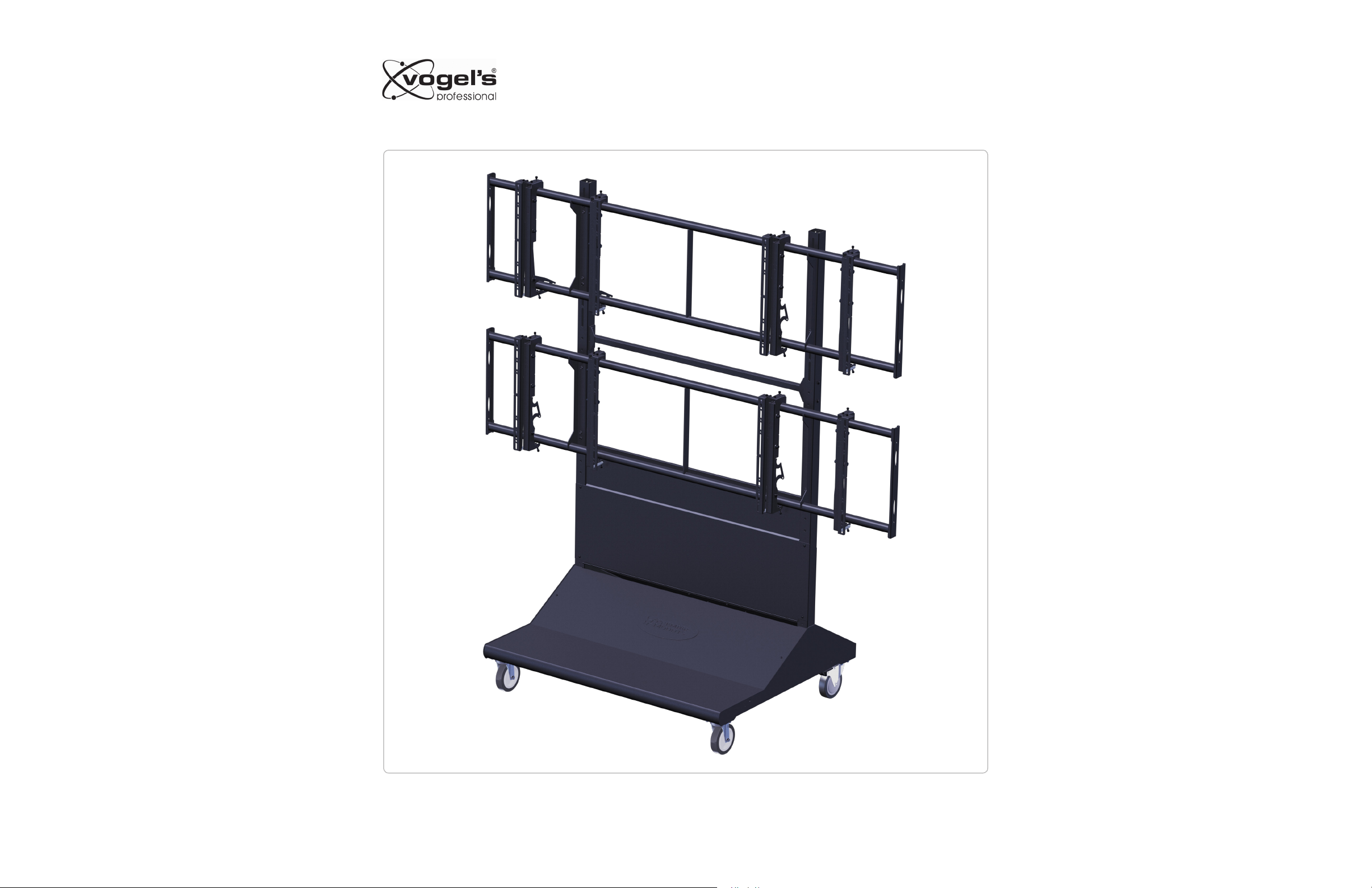
PFT8805
Installation Guide
Installationsanleitung, Guía de Instalacíon, Guida de Installazione, Guide d’Installation, Installatie gids
www.vogels.com
9532-010-Z00-00
Page 2
PFT8805
Installation Guide
Installationsanleitung, Guía de Instalacíon, Guida de Installazione, Guide d’Installation, Installatie gids
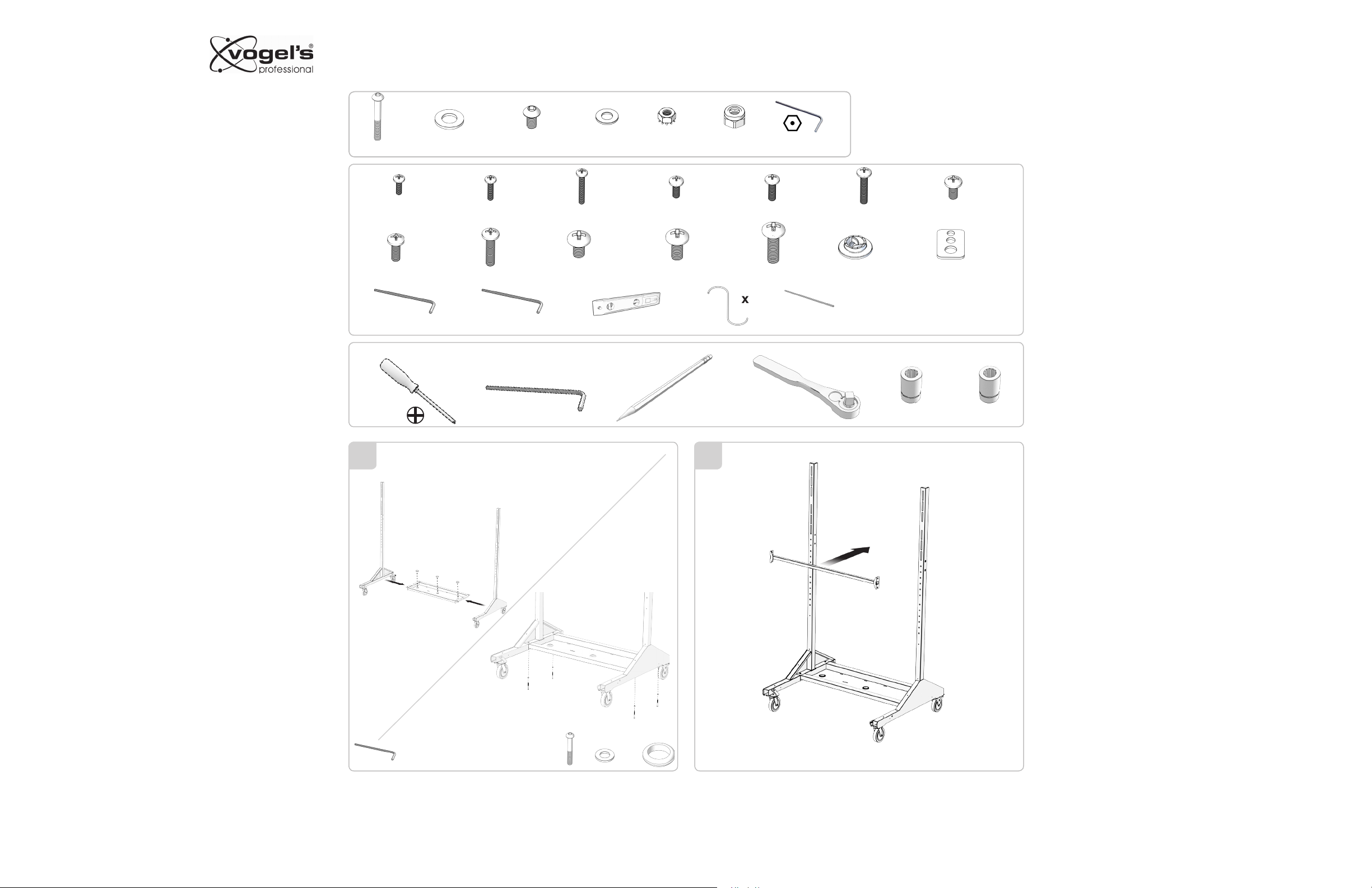
x4 x20 x20 x4
M8 x 60mm M8 M6 x 10mm M4 M4 M8
x4 x4
x24 x24 x24 x24
M4 x 12mm
x24
M6 x 16mm
5mm
Required for installation
M4 x 16mm
x24
M6 x 25mm
x1 x1
3/16”
M4 x 25mm
x1
M5 x 12mm M5 x 16mm
x24 x24 x24
M8 x 16mmM8 x 12mm
x24 x24
M8 x 25mm
x1
5mm
x1
M5 x 25mm
x1
x48
x24
M6 x 12mm
x24
13mm5/16”4mm
If this is a “one man” installation find a “friendly” clear flat
wall to place one leg assembly along side. Place the bottompanel on top of the legs channel between the two uprights.
Next place the second leg over the bottom panel so all four
through holes line up and loosely secure the bottom panel to
the legs with the four M8 x 1.25 x 60mm button head Allen
head screws and M8 flat washers supplied.
3 421
1 2
4x
5mm
4x
3x
Install the upper cross brace bet ween the inside frame rails
with the four each M8 x 60mm button head Allen screws and
flat washers supplied. Tighten all eight M8 x 60mm button
head Allen screws to create a firm frame structure at this
time.
9532-010-Z00-00
www.vogels.com
Page 3
PFT8805
Installation Guide
Installationsanleitung, Guía de Instalacíon, Guida de Installazione, Guide d’Installation, Installatie gids
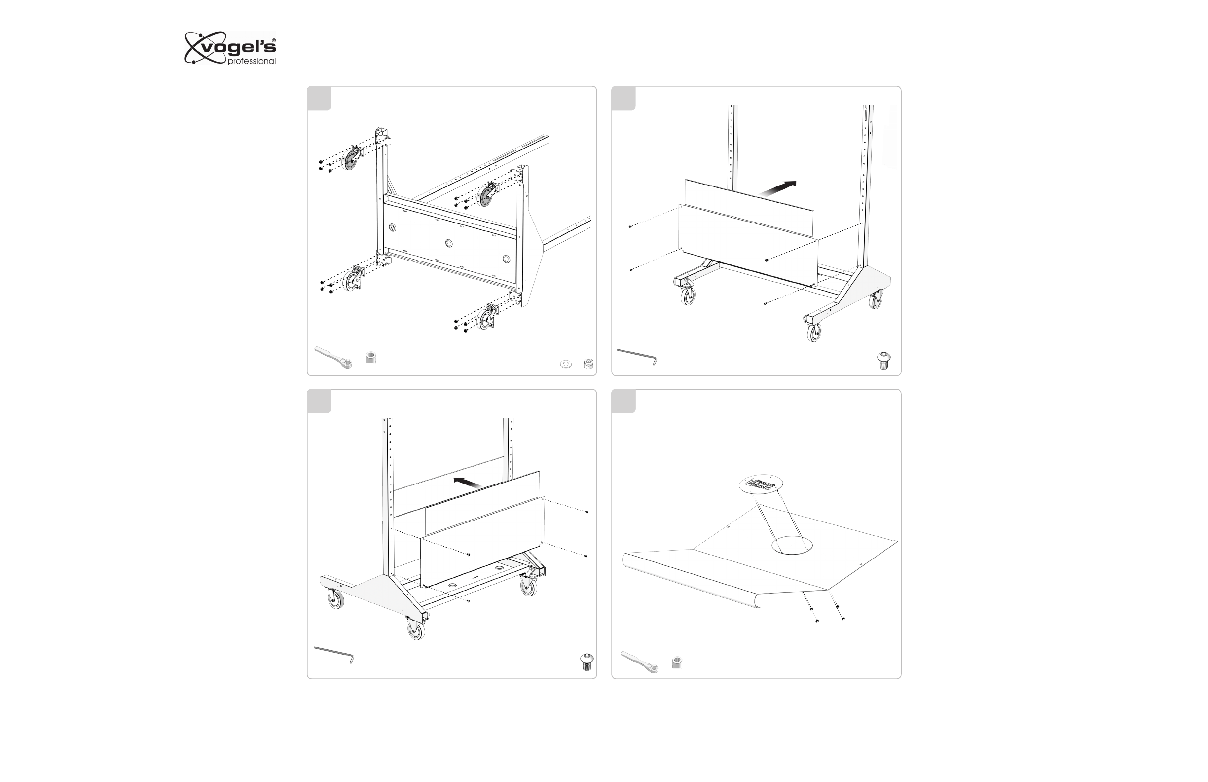
Laying the paired leg assembly first on its back and then on
its front securely install the four casters on the front and rear
of the leg assemblies using the M8 flat washers and M8 self
locking nuts supplied. Then securely install the four casters.
We recommend the two rear caster be the “locking pair”
3
13mm
16x
16x
4
Loosely install the front upper cover to the front of the cart
with the four M6 x 1.0 x 10mm”button head” Allen screws
supplied.
3
4x
4mm
Repeat the same procedure with the upper rear panel to the
leg assembly with the four each “button head” Allen screws
supplied.
Now secure firmly the four lower pan “button head” screws
to the leg assembly and tighten firmly. Repeat the same process with the front and rear upper cover panels but “don’t”
over-tighten these.
3 4
5
6
6
4mm
4x
Install the front “logo” plate to the lower panel cover with the
four each 10/32 x 1/2” “kep” nuts and flat washers supplied.
13mm
9532-010-Z00-00
www.vogels.com
Page 4

PFT8805
Installation Guide
Installationsanleitung, Guía de Instalacíon, Guida de Installazione, Guide d’Installation, Installatie gids
The rear oval panel cover can be installed before or after
final assembly of the cart with the four each M6 x 10mm
“button head” Allen head screws supplied.
7
4mm
8
4mm
Install the lower front panel cover to the frame front and
secure to the frame assembly with the four each M6 x 1.0 x
10mm “button head” Allen head screws supplied
4x
With the rear of the lower pan exposed now would be the
time to place and wire any powered suppor t products feeding the display with the power and signal cable being fed
between the front and rear upper cover panels. Power and
signal cable can also be run up through the three rubber
grommet hole in the base on the pan as well.
Once housed the rear cover panel may now be installed with
the four M6 x 10mm “button head” Allen screws supplied.
Access to the inner pan is still available through the rear
oval access cover.
3
9
4mm
4x
9532-010-Z00-00
www.vogels.com
Page 5

From this point on it is recommended that minimum two
people to properly install the cross bar assemblies to the
frame rails.
PFT8805
Installation Guide
Installationsanleitung, Guía de Instalacíon, Guida de Installazione, Guide d’Installation, Installatie gids
X
15
16
1/16"(1.3MM)
Y+ 1/16"(1.3MM)
Y
1110
Z
TV
Z = 46"(117CM)
Z = 50"(127CM) - 52"(132CM)
Z = 55"(140CM)
Z = 60"(152CM)
Y
9532-010-Z00-00
2x 2x
5mm
www.vogels.com
Page 6

PFT8805
Installation Guide
Installationsanleitung, Guía de Instalacíon, Guida de Installazione, Guide d’Installation, Installatie gids
12
5mm
2x
13
22
2x
Refer to the diagram on the previous page to find the proper
spacing for the cross bars. Once you have the proper clearance height for placement of the second cross bar install,
level and secure the second cross bar to the main frame
with the four each M8 x 60mm button head Allen screws and
flat washers supplied.
3 15
14
5mm
4x
4x
Place the first flat panel display face down on a smooth flat
surface and confirm the mounting depth and thread pitch or
your display using the depth gauge supplied.
9532-010-Z00-00
www.vogels.com
Page 7

PFT8805
Installation Guide
Installationsanleitung, Guía de Instalacíon, Guida de Installazione, Guide d’Installation, Installatie gids
Place the left and right mounting bracket (kickstand facing
in on both brackets) and confirm the center of the bracket
“notch” is exactly center between the top and bottom edge of
the display and secure with the four each appropriate pitch
and length screws supplied for your display. Note: accessory
plastic spacer are supplied in case separation between the
bracket and the display is require for clearance purposes.
16
Once center and level of the brackets are confirmed secure
17
2x3x
4x
the bracket firmly to the display. Repeat this procedure for
all nine displays being installed. Confirm the upper adjustment screws are center together by confirming all three
notches are aligned.
Starting with the lower level cross bar and confirm the
lower bracket security screws are wide open install the first
display on the lower left side and confirm it is level both in
the horizontal and ver tical plane with a spirit level. Repeat
the same procedure for the second and third display on the
lower level. Create a 1/16” clearance between the side bezel
edges of the displays and secure the display to the cross bar
with the lower security screws on each bracket.
1918
9532-010-Z00-00
www.vogels.com
Page 8

PFT8805
Installation Guide
Installationsanleitung, Guía de Instalacíon, Guida de Installazione, Guide d’Installation, Installatie gids
20
21
Once your mobile video wall is installed, make sure displays
are aligned with 1 /16” heat expansion clearance. The dual
purpose kickstand and safety lock be secured by pulling the
lower swing down lock over the lower round tube and secure
into the bracket with the M6 x 10mm Allen head screws sup plied.
9532-010-Z00-00
www.vogels.com
Page 9

Upper three stage precision alignment screws. Each bracket
has its own three part Allen head screw adjusters that can
be aligned independently to maximize the overall alignment
to flat in both the vertical and horizontal mode as well as in
and out.
PFT8805
Installation Guide
Installationsanleitung, Guía de Instalacíon, Guida de Installazione, Guide d’Installation, Installatie gids
3/16”
9532-010-Z00-00
3/16”
www.vogels.com
Page 10

PFT8805
Installation Guide
Installationsanleitung, Guía de Instalacíon, Guida de Installazione, Guide d’Installation, Installatie gids
1
5
3
11
8 3
147
2
6
9
1
10
4
7
ITEM NO.
QTY.
1 1
2 1
3 2
4 4
5 20
6 21
7 1
8 3
9 1
15
5
2
4
1213
17
16
18 6
10 1
11 1
12 4
13 4
14 2
15 1
16 16
17 2
18 2
19 1
PART NO.
3201-000-010-XX
3201-000-020-XX
0725-DCG-W02-13
0411-079-320-6X
198X-507-600-50
0398-061-091-6X
3201-000-001-XX
1558-BUD-P00-86
3201-000-005-XX
3201-000-060-XX
3201-000-006-XX
198X-265-100-35
1200-034-007-5X
3201-000-015-XX
3201-000-003-XX
1070-079-015-0X
3300-280-000-XX
3300-280-001-XX
3201-000-008-XX
REV
02
02
03
GROMMET BUNA-N RUBBER (1.50I.D) X (2.13 OD) X (.5"THK)
00
02
02 SIGN PANEL
01
05
00
VERTICAL RIGHT LEG ASSEMBLY 2X2
PLUG PUSH-IN RIBBED SQUARE CAP 2 X 2"
SCREW BUTTON HEX (M8 x 1.25 x 60)
WASHER M8 ( .335 ID ) X ( .621 OD ) X ( .063 THK )
SCREW BUTTON HEX (M6 x 1.0 x 10)
WASHER M4 ( .172 ID ) X ( .347 OD ) X ( .031 THK )
NYLON INSERT HEX LOCK NUT (M8X1.25 X .315) DIN 985
DURABLE SUPERIOR CASTERS (SWIVEL)
DURABLE SUPERIOR CASTER (LOCKING)
DESCRIPTION
VERTICAL LEFT LEG ASSEMBLY 2X2
LOWER TRAY
ACCESS PANEL
REAR PANNEL WELDED ASSY
NUT KEP (6/32"X .109)
UPPER COVER
FRONT COVER
SIGN PANEL BACKING PLATE
ITEM NO.
QTY.
1 1
2 2
3 12
4 8
5 4
6 4
7 4
PART NO.
3201-000-030-XX
3201-000-040-XX
0411-079-320-6X
201X-50A-B00-55
198X-507-600-50
4100-070-020-XX
4100-070-030-XX
REV
DESCRIPTION
01
1" HORIZONTAL TUBE BRACE ASSEMBLY
01
HORIZONTAL MOUNT ASSEMBLY
SCREW BUTTON HEX (M8 x 1.25 x 60)
WASHER LG O.D M8 (.335 ID) X (.934 O.D) X (.079)
WASHER M8 ( .335 ID ) X ( .621 OD ) X ( .063 THK )
06
LEFT MOUNTING BRACKET ASSY
06
RIGHT MOUNTING BRACKET ASSY
9532-010-Z00-00
www.vogels.com
 Loading...