

Page 1

Montage- und
Bedienungsanleitung
Assembly and
operat
ing manual
D GB F PL
Designheizkörper
P
ARIS-V/SEINE-V
Designradiator
PARIS-V/SEINE-V
DPAVZMAP0A
RO
Page 2
ACHTUNG !
1
5
7
3
6
4
8
8240 - 65
BH -8
63 - 71
min.
150
BH -40
BH
B
A
A
A
X2
X
BL -X
BL
X1
50
X2X1
X
BB
N 1234567
14
15 17
16
13
99
16
12
11
Detail C
Detail Z
10
Z
C
I
III
Entlüftung
I/II
=
Entleerung
II
18
Heizkörperrückansicht
ATTENTION !
Back of radiator
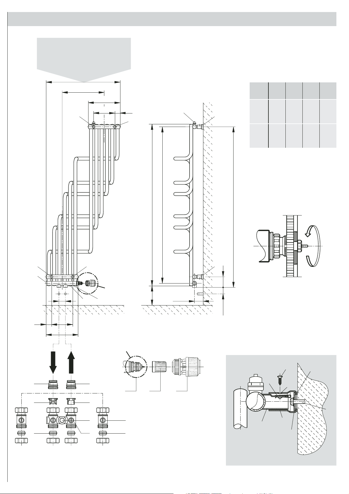
Abb. 1
BH BL X X1 X2
Entlüftung
Ventilation
1250
572 247 42 163
1500
1600
636 272 44 184
1800
Rücklauf
Return pipe
Vorlauf
Flow pipe
Entleerung
Drain
Abb. 2
2
Page 3

D
Die Installation und Inbetriebnahme Ihres Designheizkörpers PARIS-V ist von
einer zugelassenen Fachfirma durchzuführen. Bei der Installation sind die einschlägigen Normen bzw. die nationalen elektrotechnischen Sicherheitsvorschriften wie ÖVE- und VDE-Bestimmungen zu beachten.
INSTALLATION / ASSEMBLY PARIS-VINSTALLATION / MONTAGE PARIS-V
Your design radiator PARIS-V must be installed and commissioned by an
authorised company. The applicable standards and national electrotechnical
safety regulations such as the ÖVE and VDE regulations must be observed for
installation.
GB
Unter Berücksichtigung der geometrischen Maße des Designheizkörpers
PARIS-V und der Anschlusselemente (Ventile, Verschraubungen) - siehe
(Abb. 1) ist die Verrohrung vorzubereiten. Wir empfehlen, einen seitlichen
Mindestabstand zum Heizkörper von 100 mm einzuhalten.
Wird eine Elektroheizpatrone verwendet, kann diese in die 1/2" Muffen III ein-
gedichtet werden. Dabei sind die Hinweise der Montageanleitung für das
PTC-Heizelement zu beachten.
Vor der Wandmontage des Heizkörpers ist zu beachten (s. Abb. 1):
Der Vorlaufanschluss befindet sich links von der Mitte des Ventilgarniturrohres.
Gleichmäßiges Eindichten der entsprechenden Übergangsstücke 9 für die
gewählte Verschraubung (z.B. Klemmverschraubungen, Hahnblock,
Einrohrverteiler).
ZWEIROHRBETRIEB VOREINSTELLUNG (Abb. 1):
Demontage der Baustellenkappe 10. (Detail C): Einstellring des Ventiles 11
entgegen dem Uhrzeigersinn auf die gewünschte Voreinstellung drehen - der
gewünschte Einstellwert (1, 2, ..7, N) muss über der Markierung positioniert
sein.
Kv-Werteinstellungsrichtwerte bei 2K-Proportionalabweichung:
Kv = 0,13 bis 500 W Voreinstellung 1
Kv = 0,21 bis 800 W Voreinstellung 2
EINROHRBETRIEB (Abb. 1):
Eine Ventilvoreinstellung ist nicht notwendig, da das Ventil 11 werksseitig auf
Voreinstellung N justiert wurde.
Achtung: Um eine unerwünschte Erwärmung des Heizkörpers im Einrohrbetrieb bei geschlossenem Ventil möglichst gering zu halten, ist bei der
Montage des Einrohrverteilers 12 zu beachten, dass der Rücklaufeinsatz 13
im Rücklauf und der Vorlaufeinsatz 14 im Vorlauf eingebaut sind.
Vor der Einstellung des Heizkörperanteiles ist die Abdeckkappe 15 am
Einrohrverteiler 12 zu entfernen und die darunter befindliche Beipaßspindel
nach rechts bis zum Anschlag einzudrehen.
Pipework must be prepared taking into account the geometrical dimensions
of the design radiator and the connecting elements (valves, screwing) - see
(Abb. 1). We recommend a minimum distance of 100 mm to the side of the
radiator. Attention must be paid to the following:
If an electrical heater cartridge is used, it can be sealed in the 1/2" sleeve lIl.
It is important that the instructions contained in the PTC-electrical heating
assembly instructions are complied with.
Before mounting the radiator on the wall, (see Abb. 1):
Please note that the flow pipe fitting is to the left of the centre of the valve
pipe. Evenly seal the corresponding connection pieces 9 for the selected
screws (e.g. clamping screws, cock block, single pipe distributor).
PRE-SETTING FOR DOUBLE PIPE OPERATIONS (Abb. 1):
Dismantle the construction cap 10. (Detail C): Turn the valve setting ring 11
in an anti-clockwise direction to the desired pre-setting - the desired set value
(1, 2, ..7, N) must be positioned over the marking.
Kv- Guide values for settings 2K proportional offset:
Kv = 0.13 to 500 W Pre-setting 1
Kv = 0.21 to 800 W Pre-setting 2
SINGLE PIPE OPERATION (Abb. 1):
It is not necessary to pre-set the valve as the valve 11 has been pre-set at
position N.
Attention: In order to prevent the radiator reaching undesirable heat levels
in single pipe operation with closed valves, care must be taken when mounting
the single pipe distributor 12 that the return pipe insert 13 is installed in the
return pipe and inflow insert 14 is installed in the inflow pipe.
Before setting the radiator part the cap cover 15 must be removed from the
single pipe distributor 12 and the by-pass splint underneath it must be turned
to the right until impact.
Einstellwerte bei 2K Proportionalabweichung (Richtwerte):
HK-Anteil 30 % - 3,50 Umdrehungen = EINSTELLUNGSEMPFEHLUNG
HK-Anteil 35 % ................................ 3,00 Umdrehungen
HK-Anteil 40 % ................................ 2,50 Umdrehungen
HK-Anteil 45 % ................................ 2,00 Umdrehungen
HK-Anteil 50 % ................................ 1,75 Umdrehungen
WANDMONTAGE (Abb. 1 / Abb. 2):
Aufstecken der beigepackten Blechmuttern 1 auf die Montagestutzen 2 (Abb. 2)
Anreißen, Bohren der Löcher Position A und B - Bohrer ø10 - und Setzen der
Dübel entsprechend den Aufhängungsmaßen.
Empfehlung:
Messen Sie bitte vorher zur Heizkörperidentifikation die Abstandsmaße
der Montagestutzen
Nach Bedarf (Wandbeschaffenheit) sind die beigepackten transparenten
Kunststoffbeilagen 3 auf die Wandfüße 4 zu kleben (Abb. 2).
(Bitte auf saubere Klebestelle achten).
Befestigung der Wandfüße 4 und waagrechtes bzw. senkrechtes Ausrichten
derselben, wobei die Senklochbohrungen 5 in den Wandfüßen Position A nach
oben und in den Wandfüßen Position B nach unten stehen müssen. Dabei sollen
die Wandmontageschrauben 6 in der Mitte der Langlöcher der Wandfüße montiert werden. (Es wird empfohlen, die Abstandsmaße der montierten Wandfüße
vor der Heizkörperwandmontage zu kontrollieren). Verstellmöglichkeiten der
Wandfüße in Baulängen- bzw. Bauhöhenrichtung sind durch das Langloch in
der beweglichen Scheibe 8 in den Wandfüßen gegeben.
Wandmontage des Heizkörpers, indem die Montagestutzen 2 in die Wandfüße
Position A und B gesteckt und mittels Blechschraube 7 miteinander verbunden
werden. Durch das Langloch im Montagestutzen kann der Wandabstand variiert
werden.
2 (Abb. 1 u. Abb. 2)
nach.
Set Values for 2K Proportional Offset (Guide Values):
R-share 30% - 3.5 revolutions = RECOMMENDED SET VALUE.
R share 35% .................................... 3.00 revolutions
R share 40% .................................... 2.50 revolutions
R share 45% .................................... 2.00 revolutions
R share 50% .................................... 1.75 revolutions
WALL INSTALLATION (Abb. 1 / Abb. 2):
Put the sheet metal screws 1
Mark and drill the holes position A and B - ø10 drill and position the dowels
according to the suspension dimensions.
Recommendation:
Verify the distance between the mounting connections 2 (Abb. 1 and 2)
in order to identify the radiator.
If necessary, (wall condition) stick the transparent plastic shims 3 provided
onto the wall feet 4. (Abb. 2). Make sure that the adhesion surface is clean.
Mount the wall feet 4 in either a horizontal or vertical position. The countersunk
holes 5 in wall position A must point upwards and those in wall position B
must point downwards. The wall mount screws 6 must be mounted in the
middle of the oblong holes of the wall feet. (We recommend checking the
distance between the mounted wall feet before mounting the radiator on the
wall).
The length and height of the wall feet can be adjusted by means of the
oblong hole in the movable washer 8 in the wall feet.
Mount the radiator on the wall by putting the mounting connections 2 in the
wall feet in positions A and B and screwing them together with the sheet
metal screw 7. Wall space can be varied by the oblong hole in the mounting
connections.
on the mounting connections 2 (Abb. 2).
Heizkörper hydraulisch anschließen - Bei Einrohrsystemen Einrohrverteiler 12
montieren und Vorlauf- und Rücklaufleitung mit Klemmverschraubungen 16
anschließen. Bei Zweirohrsystemen sollten Absperrverschraubungen 17 eingebaut werden.
THERMOSTATKOPFMONTAGE:
Die Thermostatköpfe RA 2000, RAW; Fa. Danfoss, UNI XD Fa. Oventrop, VK;
Fa. Heimeier, D Fa. Herz, thera-DA; Fa. MNG sind direkt montierbar.
Demontage der Baustellenkappe 10, Montage des Thermostatkopfes 18.
ÄNDERUNGEN DER EINSTELLWERTE IM ZWEIROHR- UND
EINROHRBETRIEB:
Bei Bedarf können die entsprechenden Einstellwerte auch unter Anlagendruck
verstellt werden.
Connect the radiator hydraulically. For single pipe systems mount the single
pipe distributor 12 and connect the flow pipe and return pipes with clamping
screws 16. Cut-off joints 17 should be fitted to double pipe systems.
THERMOSTAT HEAD ASSEMBLY:
The thermostat heads RA 2000, RAW by Danfoss, UNI XD by Oventrop, VK
Heimeier by D Herz, thera-DA by MNG can be mounted directly.
Dismantle the construction cap 10, Mount the thermostat head 18.
CHANGING THE SET VALUES IN DOUBLE AND SINGLE PIPE
OPERATION:
If necessary, the appropriate set values can also be set while the system is
under pressure.
Page 4

INSTALLATION / MONTAGE PARIS-V
Le montage et la mise en marche de votre radiateur design PARIS-V doivent
être effectués par une entreprise spécialisée agréée. Il faut veiller lors de l’installation aux normes en vigueur et aux consignes de sécurité nationales en
matière d’électrotechnique telles que les dispositions ÖVE et VDE.
Le montage des tuyaux doit être préparé conformément aux dimensions géométriques du radiateur design et des éléments de raccord (soupapes, vissages)
(cf. Abb. 1). Nous recommandons de prévoir un espacement latéral minimum
de 100 mm d’avec le radiateur et de vous conformer aux points suivants:
En cas d’utilisation d’une cartouche chauffante, cette dernière peut être raccordée à l’un des deux manchons 1/2" III, en respectant les instructions de
PTC-Chaffage électrique montage correspondantes.
Avant la fixation au mur du radiateur, conformez-vous aux points
suivants (cf. Abb. 1): Le raccordement d’aller se trouve à gauche du milieu
du tuyau de garniture de la soupape. Etancher les raccords coniques 9 correspondants de manière homogène en fonction du vissage choisi (par ex. vissage
de serrage, bloc de robinet, distributeur monotubulaire).
F
INSTALACJA I MONTAŻ GRZEJNIKÓW
DEKORACYJNYCH PARYZ-V
Instalacja i uruchomienie grzejnika dekoracyjnego PARYŻ-V powinno zostać
wykonane przez uprawnioną do tego firmę. Należy również uwzględnić
obowiązujące obecnie normy i przepisy.
Podłączenie instalacji należy przygotować uwzględniając wymiary grzejnika
oraz jego podłączenia. Zalecane jest utrzymanie
minimalnej 100 mm odległości boku grzejnika do najbliższej ściany.
WSKAZÓWKA W przypadku instalowania grzałki elektrycznej zaleca się w tym
celu użycie mufy III 1/2”. Należy przy tym przestrzegać wskazówek, zalecanych
przez danego producenta grzałek, dotyczących samego montażu grzałki elektrycznej.
Mufę I należy zaślepić korkiem zaślepiającym, które jest dołączony do wyposażenia
dodatkowego. Mufa III powinna być również zaślepiona, kiedy nie zostanie
użyta do podłączenia grzałki elektrycznej.
WSKAZÓWKA ODNOŚNIE MONTAŻU GRZEJNIKA (Abb. 1)
Przyłącze zasilania znajduje się z lewej strony grzejnika (od strony zaworu),
patrząc na przód grzejnika. Zdemontować zaślepki zamykające podłączenia.
Prawidłowo zamontować złączki redukcyjne 9 dla wybranego połączenia.
PL
PRÉ-RÉGLAGE POUR FONCTIONNEMENT À DEUX TUYAUX (Abb. 1):
Démonter le capuchon de construction 10. (Detail C): Tourner l’anneau de
réglage 11 de la soupape dans le sens inverse des aiguilles d’une montre
jusqu’à l’obtention de la position souhaitée. La valeur de réglage souhaitée
(1, 2, ..7, N) doit être placée au dessus de la marque. Valeurs indicatives de
réglage Kv pour déviation proportionnelle de 2K.
Kv = 0,13 à 500 W: pré-réglage 1
Kv = 0,21 à 800 W: pré-réglage 2
MODE DE FONCTIONNEMENT MONOTUBULAIRE (Abb. 1):
Il n’est pas nécessaire d’effectuer un préréglae de la soupape, du fait que la
soupape 11 a été positionnée sur le préréglage N à l’usine.
Attention: Pour minimiser un réchauffement indésirable du radiateur en mode
de fonctionnement monotubulaire en position fermée de la soupape, veiller à
ce que la garniture de reflux 13 soit fixée au conduit de retour et la garniture
aller 14 dans le conduit d'alimentation lors du montage du distributeur
monotubulaire 12.
Avant de régler la partie radiateur, le capuchon 15 doit être retiré du distributeur
monotubulaire 12 et la broche de dérivation située en dessous tournée vers
la droite jusqu’à la butée.
Valeurs de réglage pour déviation proportionnelle de 2K (valeurs indicatives):
Part radiateur 30% - 3,50 tours = RÉGLAGE RECOMMANDÉ
Part radiateur 35% ................ 3,00 tours
Part radiateur 40% ................ 2,50 tours
Part radiateur 45% ................ 2,00 tours
Part radiateur 50% ................ 1,75 tours
FIXATION AU MUR (Abb. 1 et 2):
Fixer des écrous en tôle 1 inclus à la livraison aux tubulures d’assemblage 2
(Abb. 2). Traçage, perçage des trous: Position A et B. Perceuse ø10 et mise
en place des chevilles en fonction des mesures de suspension.
Recommandations:
Veuillez mesurer auparavant l’espacement des tubulures d’assemblage 2
pour déterminer le modèle de radiateur (Abb. 1 et 2).
EKSPLOATACJA W INSTALACJI DWURUROWEJ (Abb. 1)
Wybraną wartość nastawy powinno ustawiać się bez użycia specjalnych narzędzi.
Odkręcić kaptur ochronny zaworu grzejnika 10 (Detail C). Przekręcić pierścień
nastawczy zaworu 11 w kierunku przeciwnym do ruchu wskazówek zegara wybrana wartość (1,2,...7,N) musi być ustawiona ponad znacznikiem nastawy.
Wybór nastawy wstępnej odbywa się w zakresie od 1 do 7, przy skoku co 0,5
działki. Grzejniki opuszczają fabrykę z nastawieniem na najwyższą wartość kv
odpowiadającą położeniu "N". UWAGA: Wybór nastaw pomiędzy działkami,
w obszarach zakreskowanych, nie jest dozwolony!
Ustawienie wartości kv przy odchyleniu proporcjonalnym 2K:
Kv= 0,13 dla grzejników do 500 W ustawienie wstępne 1
Kv= 0,21 dla grzejników od 500 W ustawienie wstępne 2
EKSPLOATACJA W INSTALACJI JEDNORUROWEJ (Abb. 1)
Ustawienie zaworu nie jest konieczne, ponieważ zawór 11 został fabrycznie
ustawiony w pozycji „N”. UWAGA: Montując rozdzielacz systemu jednorurowego 12, należy zwrócić uwagę na właściwe umieszczenie wkładek (wkładka
zasilania 14 na wejściu i wkładka powrotu 13 na wyjściu z grzejnika). Przed
ustawieniem udziału grzejnika należy zdjąć osłonę 15 i przekręcić pokrętło w
prawo do oporu.
Wartość nastawy na rozdzielaczu przy odchyleniu proporcjonalnym 2K:
przepływ przez grzejnik 30 % - 3,50 obrotu = ustawienie zalecane
przepływ przez grzejnik 35 %...........3,00 obroty
przepływ przez grzejnik 40 %...........2,50 obrotu
przepływ przez grzejnik 45 %...........2,00 obroty
przepływ przez grzejnik 50 %...........1,75 obrotu
MONTAŻ NA ŚCIANIE (Abb. 1 i 2):
Nasadki metalowe 1 osadzić we wsporniki montażowe 2 (Abb. 2) - oznaczyć
żądaną pozycje A i B. Za pomocą wiertła ø10 wywiercić otwory i zamontować
w nich kołki rozporowe (Abb. 1).
Wskazówka:
W celu bezproblemowej instalacji należy bardzo dokładnie zmierzyć odstępy
między wspornikami 2 (Abb. 1 i Abb. 2)
Au besoin (en fonction de l’état du mur), coller les rondelles de calage transparentes en plastique 3 aux supports muraux 4 (Abb. 2) en veillant à ce que
la surface de collage soit propre.
Fixer les supports muraux 4 et les ajuster horizontalement ou verticalement
en veillant à ce que les alésages 5 des supports muraux soient situés en haut
en position A et en bas en position B. Les vis de fixation au mur 6 doivent
être insérées au centre des ouvertures longitudinales des supports muraux.
(Il est recommandé de vérifier l’espacement des supports muraux fixés avant
le montage du radiateur).
Le trou longitudinal de la plaque amovible 8 du support mural permet le
réglage vertical et horizontal des supports muraux, dans le cas où les raccords
hydrauliques ne correspondraient pas exactement.
Fixer le radiateur au mur en introdusiant les tubulures d’assemblage 2 dans les
supports muraux 2 et les assembler à l’aide des vis em tôle 7. Le trou longitudinal
de la tubulure de fixation permet de modifier la distance d’avec le mur.
Effectuer le raccord hydraulique du radiateur. Pour les systèmes monotubulaires, monter le distributeur monotubulaire 12 et raccorder les canalisations
d’aller et de reflux à l’aide des vissages de serrage 16. Pour les systèmes à
deux tubes, il est nécessaire d’intégrer des vissages de fermeture 17.
MONTAGE DE LA TÊTE DE THERMOSTAT:
Les têtes de thermostat RA 2000, RAW Danfoss, UNI XD Oventrop, VK
Heimeier, D Herz, thera-DA MNG peuvent être montées directement.
Démonter capuchon de construction 10, Montage de la tête de thermostat 18.
MODIFICATION DES VALEURS DE RÉGLAGE EN MODE DE
FONCTIONNEMENT MONOTUBULAIRE ET À DEUX TUBES:
Au besoin, il est possible de modifier les valeurs de réglage sous pression.
W razie potrzeby, zależnie od stanu ściany, można wykorzystać załączone do zestawu
elementy wspomagające montaż z tworzywa sztucznego 3 i nakleić na wsporniki
4 (Abb. 2). Przy tym należy zwrócić uwagę na czystość klejonych powierzchni.
Zamocować wsporniki ścienne 4 w pozycji A i B, przy czym otwory 5 we
wspornikach ściennych, zaleca się w pozycji A skierować w górę, natomiast
w pozycji B w dół. Śruby służące do montażu do ściany 6 muszą zostać zamocowane w samych wspornikach 4 (proponuje się skontrolowanie odstępów
między wspornikami przed
zamontowaniem grzejnika). Osadzić wsporniki montażowe 2 we wspornikach
ściennych 4 w pozycji A i B, a następnie zamocować je przy pomocy śrub
metalowych 7 (służą one do określenia odległości od ściany i wypoziomowania
grzejnika). W przypadku , gdy przyłącza zasilania i powrotu nie pasują idealnie
do siebie, dobór odpowiedniej odległości regulowany jest przy pomocy
podłużnego otworu w ruchomej blaszce 8 umieszczonej we wsporniku
ściennym 4.
Grzejnik podłączyć do instalacji. W przypadku instalacji jednorurowej użyć kurka
kulowego 12 oraz połączyć przewody za pomocą złączki zaciskowej 16. Natomiast
do instalacji dwururowej można użyć podłączenie 17 pokazane na Abb. 1, lub
inne dostosowane do grzejnika zamontowanego w instalacji dwururowej.
MONTAŻ GŁOWICY TERMOSTATYCZNEJ:
Bezpośrednio na zawór (bez adaptera) można montować następujące głowice termostatyczne (nie objęte programem dostawy): Danfoss (RTD-R InovaTM3140, RTS-R
Everis 4240); Heimeier VK; Herz D; Honeywell thera-DA; Oventrop Uni XD. Odkręcić
kaptur ochronny zaworu grzejnika 10. Zamontować głowicę termostatyczną 18.
ZMIANY NASTAW WARTOŚCI PRZY EKSPLOATACJI W SYSTEMIE
DWU- I JEDNORUROWYM:
korekty nastaw zaworów można wprowadzać także pod ciśnieniem roboczym.
Page 5

INSTALARE ŞI MONTAJ PARIS-V
Montajul şi punerea în funcţiune a radiatorului design PARIS-V trebuie făcute de
către o societate autorizată. De asemenea, trebuie respectate standardele şi normele
naţionale din domeniul electrotehnic, cum ar fi ÖVE şi VDE.
Pregătiţi sistemul de distribuţie a ţevilor ţinând cont de dimensiunile şi geometria
radiatorului design, cât şi de elementele de conectare (robineţi, racorduri) (Abb. 1).
Este recomandabil să se păstreze o distanţă de minimum 100 mm faţă de radiatorul următor, şi a se citi instrucţiunile următoare.
Dacă se foloseşte un modul de încălzire electric, trebuie cuplat în racordul III.
Urmaţi instrucţiunilede montaj ale modulului electric de încălzire.
Înainte de a monta radiatorul pe perete (Abb. 1):
Racordul de alimentare se află în stânga axei racordului supapei.
Îndepărtaţi dopul de pe filetul de 1/2". Strângeţi bine racordurile conice 9
corespunzătoare, în funcţie de înşurubarea dorită (strângere prin înşurubare,
placa de robineţi, distribuitorul monotubular).
REGLAJE PREMERGĂTOARE FUNCŢIONĂRII BITUBULARE (Abb. 1):
Demontaţi capacul 10. (Detail C) Învârtiţi inelul de reglaj al supapei în sens
invers acelor de ceasornic până la poziţia dorită. Valoarea dorită (1, 2...7, N)
trebuie poziţionată în dreptul marcajului.
Valori orientative Kv pentru deviaţia proporţională 2K:
Kv = 0,13 la 500 W ante - reglaj 1
Kv = 0,21 la 800 W ante – reglaj 2
FUNCŢIONAREA MONOTUBULARĂ (Abb. 1):
Ante-reglajul supapei nu este necesar, doarece supapa 11 a fost reglată din
fabricaţie.
Atenţie: Pentru a preîntâmpina încălzirea excesivă a radiatorului în timpul
funcţionării monotubulare, cu supapa închisă, atenţie la montajul distribuitorului
monotubular 12: inserţia corespunzătoare returului 13 este fixată pe returul
instalaţiei, iar inserţia corespunzătoare turului 14 este fixată pe turul instalaţiei.
Înainte de a fixa radiatorul, trebuie înlăturat dopul 15 de pe distribuitorul
monotubular 12 iar robinetul by-pass de dedesubt trebuie învârtit maxim spre
dreapta.
RO
Valori orientative Kv pentru deviaţia proporţională 2K:
Cotă – radiator 30% - 3,5 rotaţii = VALOAREA RECOMANDATĂ
Cotă -radiator 35% .............................3,00 rotaţii
Cotă -radiator 40% .............................2,50 rotaţii
Cotă -radiator 45% .............................2,00 rotaţii
Cotă -radiator 50% .............................1,75 rotaţii
FIXAREA PE PERETE (Abb. 1 / Abb. 2):
Fixaţi piuliţele 1 în ştuţurile de montaj 2 (Abb. 2). Marcaţi şi faceţi găurile pentru poziţia A – gaura ø10 – şi poziţionaţi diblurile în funcţie de mărimea masei
suspendate. (Abb. 1)
Recommandare:
Verificaţi în primul rând distanţa între ştuţuri 2 (Abb. 1 şi 2), pentru a putea
determina modelul radiatorului.
Dacă e nevoie, în funcţie de starea peretelui, adăugaţi elementul de fixare 3, din
plastic transparent, pe perete 4 (Abb. 2). Asiguraţi-vă că suprafaţa de adeziune
este curată.
Fixaţi şi aliniaţi orizontal suportul de montaj 4 pe perete; gaura de scurgere 5 de
la baza peretelui trebuie îndreptată în sus în poziţia A şi în jos în poziţia B.
Şuruburile de fixare 6 trebuie plasate în centrul găurilor longitudinale ale suportului mural. (Vă recomandăm să verificaţi spaţiul dintre suporturile murale,
înainte de a monta radiatorul pe perete).
Dacă componentele hidraulice nu se potrivesc perfect, înălţimea şi lungimea pot
fi reglate cu ajutorul găurii alungite de pe plăcuţa situată pe suport 8.
Montajul radiatorului pe perete: introduceţi partea superioară a suportului de
montaj 2 în suportul de instalaţie în pziţiile A şi B şi racordaţi-o cu ajutorul unui
şurub din oţel 7. Distanţa până la perete se poate regla în funcţie de găurile din
suportul de montaj.
Racordaţi partea hidraulică a radiatorului. Pentru sistemele monotubulare, montaţi
distribuitorul monotubular 12 şi cuplaţi turul şi returul cu ajutorul şuruburilor 16.
Pentru sistemele bitubulare se vor folosi şuruburi de închidere 17 .
MONTAJUL CAPULUI TERMOSTATIC:
Tipurile de cap termostatic RA 2000, RAW Danfoss, UNI LTD Oventrop, VK
Heimeier - D Herz, thera- DA MNG pot fi montate direct.
Demontaţi capacul 10. Montaţi capul termostatic 18.
MODIFICAREA VALORILOR DE REGLAJ PENTRU FUNCŢIONAREA
MONOTUBULARĂ ŞI BITUBULARĂ:
Dacă e necesar, este posibil să se modifice valorile de reglaj în timp ce sistemul
este sub presiune.
Page 6
HEIZKÖRPERBESCHREIBUNG
Die Heizkörper der Familie PARIS-V sind elegante Designheizkörper, geeignet
für Warmwasserzentralheizungen mit max. Betriebstempe-ratur von 110 °C
und max. Betriebsüberdruck von 10 bar.
Der gleichbleibende hohe Qualitätsstandard unterliegt einer laufenden Eigenund Fremdüberwachung.
Nacharbeiten am Heizkörper (z.B. Schweißarbeiten) durch den Kunden sind
nicht erlaubt.
Die Produktfamilie PARIS-V kann auch mit einer Elektrozusatzheizung ausgestattet werden, wobei die nachfolgenden Empfehlungen einzuhalten sind:
D
DESCRIPTION OF RADIATOR
PARIS-V radiators are elegant design radiators suitable for warm water central
heating systems with a maximum operating temperature of 110 °C and a
maximum operating pressure of 10 bar.
The consistently high quality standards are subject to continual internal and
external controls.
Customers may not carry out work (e.g. welding) on the radiators.
PARIS-V products can also be fitted with an additional electrical heating
element if the following recommendations are complied with:
GB
Heizkörperdimension,
Baulänge x Bauhöhe [mm]
572 x 1250 300 572 x 1500 300 300
636 x 1600 300 300
636 x 1800 300 300
Aufgrund der besonderen hydraulischen Maßnahmen, die für einen optimalen
Zentralheizungsbetrieb des Heizkörpers erforderlich sind, wird für den Betrieb
des Heizkörpers mit Elektropatrone das erste, vorlaufnahe Steigrohr nicht
beheizt, d. h. fünf Steigrohre mit den entsprechenden Rohrbögen sind dann
beheizt. Die hydraulische Leistungsregelung - Raumtemperaturregelung erfolgt bei der Heizkörperfamilie PARIS-V durch das, im Heizkörper integrierte
Thermostatventil, wobei durch eine speziell entwickelte Heizwasserführung
die hydraulische Funktion dieses Designheizkörpers hergestellt wird.
Das Wandmontagekonzept ist ein auf fertige Wände konzipiertes
System.
BEDIENUNG UND PFLEGE
Die Designheizkörper PARIS-V sind hochwertige Produkte, die nicht nur der
Raumheizung dienen, sondern auch zur Trocknung von Handtüchern geeignet
sind. Daher ist zu beachten, dass sie heiße Oberflächen besitzen. Es dürfen
nur Textilien, die mit Wasser gewaschen wurden, getrocknet werden.
Selbstverständlich ist es unzulässig, diesen Heizkörper als Kletter- oder Sportgerät zu benutzen.
Zur Reinigung der Heizkörperoberflächen sind schonende, nicht scheuernde
Reinigungsmittel zu verwenden. (Vergoldete Oberflächen dürfen nur mit
warmem Wasser und weichen Lappen gereinigt werden.)
Für den Fall des Elektroheizungsbetriebes muss die Heizwasserausdehnung
immer bis zum Expansionsgefäß gewährleistet sein, z. B. durch Öffnen des
Rücklaufventiles. Um Wärmeverschlep-pungen in das Heizungsnetz zu vermeiden, wird in diesem Fall empfohlen, das Thermostatventil zu schließen.
Selbstverständlich darf die Elektroheizung nur in Betrieb genommen werden,
wenn der Heizkörper komplett mit Heizungswasser gefüllt ist.
Wird der Heizkörper elektrisch betrieben, darf er aus sicherheitstechnischen
Gründen nicht komplett abgedeckt werden.
PTC-Elektroheizelement [W] bei 60 °C
RAL/Sanitärfarben verchromt, vergoldet
D
Radiator Sizes, total length
x total height [mm]
572 x 1250 300 572 x 1500 300 300
636 x 1600 300 300
636 x 1800 300 300
Owing to the special hydraulic measures required for optimal heating performance of the radiator, the first tube near the flow pipe is not heated if the
radiator is operated with an electrical cartridge, i. e. five tubes are then heated with the appropiate pipes.
The hydraulic regulator - room temperature control for PARIS-V radiators is
carried out by a thermostat valve integrated in the radiator, a specially designed hot water system provides the design radiator’s hydraulic function.
The wall installation concept is a system designed for finished walls.
OPERATION AND CARE
PARIS-V design radiators are high quality products which are suitable for drying
towels as well as heating rooms. For this reason it is important to remember
that they have hot surfaces. Only textiles that have been washed in water
may be dried.
Of course it is not permitted to use the radiators as climbing frames or sports
equipment.
The radiator surfaces must be cleaned with gentle non-scouring cleansing
agents. (Gold-plated surfaces may only be cleaned with warm water and soft
cloths.)
For electrical heating operations the heating water must always be able to
expand to the expansion tank, e.g. by opening the non-return valve. To prevent
heat being transferred to the heating network in this case, we recommend
closing the thermostat valve. Of course, the electrical heating may only be
switched on after the radiator has been completely filled with water.
For safety reasons, the radiator must not be covered completely if it is operated
electrically.
PTC-Electrical heating [W] at 60 °C
RAL/sanitary colours chrome/gold-plated
GB
GARANTIEBEDINGUNGEN
Vogel & Noot gewährt, vom Tage der Lieferung an, für die Designheizkörper
PARIS-V eine Garantie von 10 Jahren auf wasserseitige Dichtheit und Funktion
bzw. 5 Jahre auf die beschichtete Oberfläche.
Transportschäden sind spätestens am nächsten, dem Liefertag folgenden
Werktag dem Lieferanten zu melden.
Im Garantiefall ist die Rechnung vorzulegen.
Die Garantie bezieht sich auf alle Teile, die nachweisbar mit einem Material-
fehler behaftet sind oder die infolge fehlerhafter Ausführung schadhaft werden.
Normale Abnützungen, Schäden durch höhere Gewalt, vorsätzliche oder fahr-
lässige Beschädigungen, die durch das Nichtbeachten der Montage-, Gebrauchsund Pflegeanweisungen entstehen, sind von der Garantieleistung ausgenommen.
Wir übernehmen keine Garantie für Schäden, die aufgrund ungeeigneter oder
unsachgemäßer Verwendung, fehlerhafter Montage und / oder Inbetriebsetzung
durch Dritte, fehlerhafter oder nachlässiger Behandlung, ungeeigneter Betriebsmittel, Fremdkörpereinschwemmungen, mangelhafter Bauarbeiten, chemischer,
elektrochemischer oder elektrischer Einflüsse entstehen, sofern sie nicht auf
unser Verschulden zurückzuführen sind.
Im Falle einer von Vogel & Noot anerkannten mangelhaften Ausführung oder
eines anerkannten Materialfehlers, behält sich Vogel & Noot das Recht vor,
mangelhafte Teile instand zu setzen oder durch mangelfreie Teile zu ersetzen.
Ausgetauschte Teile gehen in das Eigentum von Vogel & Noot über.
Die Garantielaufzeit wird infolge ihrer langen Dauer bei Inanspruchnahme
(Instandsetzung oder Ersatzlieferung) durch den Endkunden über diesen
Zeitraum hinaus nicht verlängert.
Vogel & Noot behält sich das Recht vor, ohne vorhergehende Ankündigung
die technischen Merkmale seiner Produkte zu ändern.
D
WARRANTY CONDITIONS
PARIS-V design radiators are covered by Vogel & Noot 10 year warranty for
water side sealing and function and a 5 year warranty for coated surfaces
from the date of delivery.
Damage caused during transport must be reported to the supplier no later
than the next working day after delivery.
The invoice must be submitted when making a warranty claim.
The warranty is valid for all parts with proven material defects or which
become defective as a result of faulty workmanship.
Normal wear, damage caused by force majeure, damage caused deliberately
or through negligence, non-compliance with the installation, operating and
care instructions are not included in the warranty.
We accept no guarantee claims for damage resulting from improper or inappropriate use, faulty installation and/or commissioning by third parties, incorrect
or negligent treatment, unsuitable operating agents, foreign bodies in the
water, faulty workmanship, chemical, electrochemical or electrical influences
that were not caused by us.
In the event that Vogel & Noot accepts that finishing was faulty or that material
was defective, Vogel & Noot reserves the right to repair defective parts or to
replace them with parts in good condition. Parts which have been replaced
become the property of Vogel & Noot.
As a result of its length in the event of warranty claims (repair or supply of
spare parts) by the final customer, the warranty will not extended beyond this
term.
Vogel & Noot reserves the right to alter the technical specifications of its
products without prior notice.
GB
Page 7

DESCRIPTION DU RADIATOR
Les radiateurs de la série PARIS-V sont d'élégants radiateurs design, convenant
aux systèmes de chauffage central à eau chaude. La température de service
maximum est de 110 °C et la surpression de service maximum de 10 bar.
Le haut niveau de qualité constant est soumis à des contrôles internes et
externes de façon continue.
Les clients ne sont pas autorisés à effectuer des travaux ultérieurs sur les
radiateurs (soudures, par exemple).
Les produits de la gamme PARIS-V peuvent également être équipés d’un dispositif
de chauffage électrique complémentaire, à condition de respecter les recommandations suivantes:
Dimensions du
radiator [mm]
572 x 1250 300 572 x 1500 300 300
636 x 1600 300 300
636 x 1800 300 300
En raison des mesures hydrauliques spéciales nécessaires en vue d’un fonctionnement optimal du radiateur de chauffage central, le premier tuyau ascendant proche
du conduit d’alimentation n’est pas chauffé lorsque le radiateur fonctionne au
moyen d’une cartouche chauffante, c’est à dire que cinq tuyaux ascendants ainsi
que les coudes de tuyaux correspondants sont chauffés dans ce cas. Pour la gamme
de radiateurs PARIS-V, le réglage de la puissance/de la tempèrature de la pièce
s’effectue au moyen d’une soupape de thermostat intégrée au radiateur, la
fonction hydraulique de ce radiateur design étant assurée au moyen d’un
système d’amenée de l’eau de chauffage spécialement élaboré.
Le système de fixation au mur est conçu pour des murs déjà finis.
PTC-Chauffage électrique [W] à 60 °C
RAL/coloris sanitaires chromé/doré
F
OPIS GRZEJNIKA
Grzejniki PARYŻ-V są eleganckimi, grzejnikami wzorniczymi. Przystosowane są
do podłączenia w systemach centralnego ogrzewania przy maksymalnej temperaturze pracy 110°C oraz maksymalnym ciśnieniu roboczym 1,0MPa (10 bar).
Niezmienne, wysokie standardy jakości podlegają ciągłej kontroli służb
wewnętrznych, jak i zewnętrznych.
Nie zezwala się na prace naprawcze przy grzejnikach (np. spawanie)
wykonywane na własną rękę, a także inne działania mogące powodować
deformację grzejnika, lub zniszczenie powłoki lakierniczej.
Rodzina produktów PARYŻ-V może zostać wyposażona w grzałkę elektryczną,
przy czym należy zwrócić uwagę na następujące dane:
wymiary grzejnika
szerokość/wysokość [mm]
572 x 1250 300 572 x 1500 300 300
636 x 1600 300 300
636 x 1800 300 300
Regulacja temperatury w pomieszczeniu odbywa się przy użyciu głowicy
termostatycznej zamontowanej na zaworze grzejnikowym.
Idea montażu na ścianie pomyślana jest jako system przeznaczony
dla gotowych ścian.
PL
PTC-grzałka elektryczna [W] przy 60 °C
RAL/kolory sanitarne chromowany/pozłacan
y
UTILISATION ET ENTRETIEN
Les radiateurs design PARIS-V sont des produits de haute qualité qui ne servent
pas seulement à chauffer les pièces mais peuvent également être utilisés pour
faire sécher des serviettes de toilette. Dans ce cas, il faut veiller à ce que leur
surface soit chaude. Il ne faut utiliser que des textiles lavés avec de l’eau et secs.
Bien entendu, on ne doit pas grimper sur les radiateurs ni s’en servir comme
d’appareils de sport.
Pour nettoyer la surface des radiateurs, veillez à employer des produits non
agressifs et non récurants. (Les surfaces dorées ne doivent être nettoyées
qu’avec un chiffon doux et à l’eau chaude.)
En cas de fonctionnement en mode électrique des radiateurs, il faut veiller à ce
que la dilatation de l’eau chaude soit assurée jusqu’au récipient d’expansion,
par exemple en ouvrant la soupape de reflux. Pour éviter que la chaleur ne soit
entraînée dans le réseau de chauffage, il est recommandé de fermer la soupape
du thermostat dans ce cas. Naturellement, le mode de fonctionnement électrique
ne doit être mis en marche qu’une fois le radiateur entièrement rempli d’eau.
Pour des raisons de sécurité, le radiateur ne doit pas être recouvert intégralement
lorsqu’il marche en mode électrique.
CONDITIONS DE GARANTIE
Vogel & Noot accorde une garantie de 10 ans en matière d'étanchéité et de
fonctionnement pour les radiateurs design de la gamme PARIS-V à partir du
jour de la livraison ainsi qu’une garantie de 5 ans pour les surfaces peintes.
Les dommages survenus pendant le transport doivent être signalés au fournisseur au plus tard un jour ouvrable après la livraison.
En cas d’un recours à la garantie, la facture doit être présentée.
La garantie s’étend aux pièces comportant un défaut de matériel avéré ou
devenues défectueuses en raison d’une erreur de construction.
L'usure normale, les dommages survenus dans le cadre de catastrophes naturelles,
les détériorations intentionnelles ou résultant de négligences, du non respect des
instructions d’assemblage, d’utilisation ou d’entretien sont exclus de la garantie.
Aucune garantie n’est accordée pour des dommages survenus en raison
d’une utilisation non conforme ou impropre, d’un montage et/ou d’une mise
en service non appropriée par des tiers, d’une manipulation impropre ou
négligente, d’un outillage non approprié, de l’inclusion de corps étrangers, de
travaux de construction défectueux, d’influences chimiques, électrochimiques
ou électriques, du moment où nous n’en sommes pas responsables.
Dans le cas d’une erreur de construction ou d’un défaut de matériel avérés,
Vogel & Noot se réserve le droit de réparer les parties défectueuses ou de les
remplacer. Les pièces échangées deviennent alors propriété de Vogel & Noot.
Dans le cas où le client final a recours à la garantie (remise en état ou échange d'une pièce), la durée de garantie n’est pas prolongée au delà de cette
période en raison de sa longue durée.
Vogel & Noot se réserve le droit de modifier les spécifications techniques de
ses produits sans avis préalable.
F
F
OBSŁUGA I UTRZYMANIE CZYSTOŚCI
Grzejniki dekoracyjne PARYŻ-V są produktami wysokiej jakości, służącymi nie
tylko do ogrzewania pomieszczeń, ale i do np. suszenia ręczników. Z tego też
względu nie należy zapominać, że posiadają one gorące powierzchnie.
Nie zezwala się natomiast na używanie grzejników do innych celów, jak np.
drabinki sportowe.
Do czyszczenia powierzchni grzejników należy stosować środki o łagodnym
działaniu, nie uszkadzających powierzchni. Do czyszczenia powierzchni grzejników
należy stosować środki o łagodnym działaniu, nie uszkadzających powierzchni.
W razie użycia grzałki elektrycznej, przyrost objętości wody musi być skompensowany poprzez otwarcie zaworu powrotnego. Zaleca się także zamknięcie
głowicy termostatycznej na zasilaniu.
Ogrzewanie elektryczne może zostać uruchomione tylko wtedy, gdy grzejnik
wypełniony został całkowicie wodą.
Jeżeli grzejnik działa jako elektryczny poprzez użycie grzałki elektrycznej, to ze
względów technicznych oraz bezpieczeństwa nie może być całkowicie zakryty.
WARUNKI GWARANCJI
Na grzejniki dekoracyjne PARYŻ-V udzielana jest 10-letnia gwarancja na
szczelność grzejnika oraz 5-letnia na zastosowaną powłokę na powierzchni
grzejnika.
Gwarancja jest liczona od dnia zakupu, potwierdzonego dowodem zakupu,
np. fakturą.
Szkody powstałe w wyniku transportu powinny zostać zgłoszone do dostawcy
grzejnika najpóźniej następnego dnia roboczego po dacie zakupu towaru.
Gwarancja obejmuje grzejnik, lub jego części, których wadliwe działanie spowodowane jest jednoznacznie wadą materiałową, lub których nieprawidłowe
działanie wynikło z wadliwego wyrobu.
Normalne ślady zużycia, szkody powstałe w wyniku działania siły wyższej,
szkody spowodowane umyślnie, lub nieumyślnie poprzez nieprzestrzeganie
zasad montażu, lub użycia nie podlegają warunkom gwarancji.
Gwarancja nie obejmuje szkód powstałych wskutek nieprawidłowego montażu,
nieprawidłowej eksploatacji i/lub działalności osób trzecich, błędnych lub
nieodpowiednich narzędzi, przedostania się ciał obcych do wnętrza, błędnych
robót budowlanych, oddziaływań chemicznych, elektrochemicznych i elektrycznych, o ile nie są one spowodowane z winy producenta.
W przypadku wyrobu uznanego przez producenta za wybrakowany ze względu
na budowę lub wady materiałowe, producent zastrzega sobie prawo do
wymiany, lub naprawy wybrakowanych części, lub samego grzejnika. Rzeczy
podlegające wymianie stają się własnością producenta
Okres gwarancji nie zostaje przedłużony o czas potrzebny do naprawy/wymiany
produktu, lub przekazania części zamiennych.
Vogel & Noot zastrzega sobie prawo do zmiany parametrów technicznych
swoich wyrobów.
PL
PL
Page 8

DESCRIEREA RADIATORULUI
Radiatoarele PARIS-V sunt radiatoare design elegante pentru băi, adecvate
sistemelor de încălzire centrală, cu o temperatură maximă de funcţionare de
110°C şi o presiune maximă de 10 bar.
Standardul înalt de calitate este supus unor controale continue, interne şi
externe.
Beneficiarilor le sunt interzise intervenţiile ulterioare asupra radiatoarelor.
(ex: sudura).
Produselor PARIS-V li se poate ataşa un element electric de încălzire adiţional,
cu condiţia ca următoarele recomandări să fie respectate:
RO
Dimensiuni radiator
[mm]
572 x 1250 300 572 x 1500 300 300
636 x 1600 300 300
636 x 1800 300 300
Datorită măsurilor hidraulice speciale, necesare pentru optima funcţionare a
radiatorului, prima ţeavă de lângă circuitul de tur nu este încălzită în cazul în care
radiatorul funcţionază cu cartuţul caloric. Astfel, sunt încălzite 5 ţevi ascendente.
Reglajul hidraulic - controlul temperaturii pentru radiatoarele din gama PARIS-V
este asigurat de un termostat integrat în radiator, funcţiunea hidraulică a radiatorului
design fiind asigurată cu ajutorul unui sistem special elaborat de transport al
apei calde.
Sistemul de instalare murală a fost conceput pentru pereţi finisaţi.
UTILIZARE ŞI ÎNTREŢINERE
Radiatoarele PARIS-V sunt produse de înaltă calitate care nu doar încălzesc încăperi,
ci pot fi utilizate şi pentru a usca prosoape. Trebuie reţinut că suprafeţele sunt
fierbinţi. Pot fi puse la uscat numai textile spălate în apă.
Bineînţeles, radiatoarele nu pot fi utilizate ca şi echipamente de sport.
Suprafeţele radiatoarelor trebuie curăţate cu soluţii anticorozive.
Suprafeţele aurii pot fi curăţate cu apă caldă şi cu materiale moi.
PTC-Încălzire electrică [W] la 60 °C
RAL - culori sanitare Cromat/Auriu
RO
În cazul funcţionării electrice a radiatoarelor, trebuie asigurată dilatarea apei în
vasul de expansiune, prin deschiderea supapei de uni-sens. Pentru a evita transferul căldurii în sistem, este recomandabil să se închidă robinetul termostatic.
Bineînţeles, radiatorul electric poate fi pus în funcţiune numai după ce a fost
complet umplut cu apă.
Din motive de siguranţă, radiatorul nu trebuie acoperit în întregime, în cazul în
care funcţionează electric.
CONDIŢII DE GARANŢIE
Vogel & Noot acordă o garanţie de 10 ani din punct de vedere al etanşeităţii şi al
funcţionării radiatoarelor design PARIS-V, din ziua livrării, şi o garanţie de 5 ani
pentru suprafeţele vopsite sau metalizate.
Deteriorarea din timpul transportului trebuie anunţată furnizorului cel târziu
următoarea zi lucrătoare după livrare.
În cazul recurgerii la garanţie, trebuie prezentată factura.
Garanţia acoperă piesele componente cu defecte materiale dovedite sau care sau
defectat ca urmare unei erori de construcţie.
Sunt excluse de la garanţie uzura normală, defecţiunile provocate de catastrofe
naturale, cele provocate cu bună ştiinţă, sau din neglijenţă, incompatibilitatea cu
instalaţia, nerespectarea instrucţiunilor de montaj, funcţionarea şi întreţinerea.
Nu se oferă garanţie pentru defecţiuni rezultând din utilizarea improprie sau
neadecvată, din montajul sau punerea în funcţiune improprie de către terţi, din
manipularea neglijentă, agenţi de operare nepotriviţi, corpi străini în apă, montaj
defectuos, agenţi chimici, electrochimici sau electrici, de care noi nu suntem
responsabili.
În cazul în care se constată defecţiuni de construcţie sau materiale defecte,
Vogel & Noot îşi rezervă dreptul de a repara piesele în cauză, sau să le înlocuiască.
Piesele schimbate devin proprietatea Vogel & Noot.
RO
În cazul în care beneficiarul a apelat la garanţie, (reparaţie sau înlocuire piesă de
schimb), garanţia nu va fi extinsă.
Vogel & Noot îşi rezervă dreptul de a modifica specificaţiile tehnice ale produselor, fără înştiinţare prealabilă.
 Loading...