

Page 1
NERO
Designheizkörper / designradiators
Montage- und Bedienungsanleitung
Assembly and operating manual
heatingthroughinnovation.
DNEMYMAP0C
DGBF PL
Page 2
64 - 76
min.
150
50
B
B
A
A
A
- 170
B
B
A
69 50 51
- 219
166
286 - 459
166
ACHTUNG ! Heizkörperrückansicht
ATTENTION ! Back of radiator
UWAGA! Widok ściany tylnej
grzejnika
530 1019
530 1419
630 1419
530 1819
630 1819
B
II
A
I
II
III E
*
Bauhöhe / Height
/Wysokość
Baulänge / Length
/Szerokość
Vorlauf / Flow / Zasilanie
Rücklauf / Return / Powrót
Entlüftung / Ventilation
/Odpowietrznik
Montagestutzen /
Mounting connector /Zestaw montażowy
E
a
Abb.4 / Fig.4
/Rys.4
Abb.1 / Fig.1 /
Rys.1
Abb.2 / Fig.2 /
Rys.2
b
c
2
1
0
3
4
5
Abb.5 / Fig.5 / Rys.5
2
1
5
7
3
6
4
8
Abb.3 / Fig.3 / Rys.3
Page 3

Installation/Assembly NERO
GBD
Die Installation und Inbetriebnahme Ihres Designheizkörpers NERO
ist von einer zugelassenen Fachfi rma durchzuführen.
Bei der Installation sind die einschlägigen Normen bzw. die nationalen elektrotechnischen Sicherheitsvorschriften wie ÖVE- und VDEBestimmungen zu beachten.
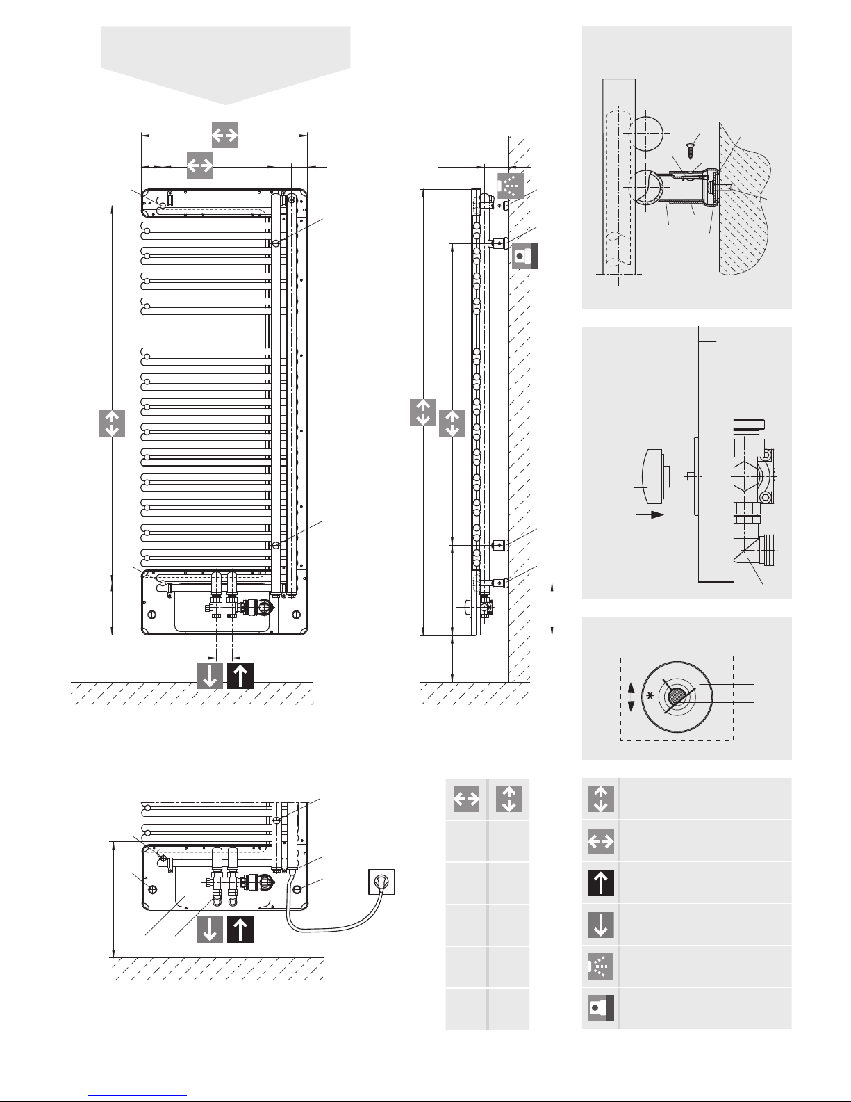
Unter Berücksichtigung der geometrischen Maße des Designheizkörpers NERO ist die Verrohrung vorzubereiten (Abb. 1 und 2).
Wir empfehlen einen seitlichen Mindestabstand zum Heizkörper von
100 mm einzuhalten. Dabei ist Nachfolgendes zu berücksichtigen:
Wird ein Elektroheizelement verwendet, kann dieses in die 1/2“ Muffe
I eingedichtet werden (Abb. 2). Dabei sind die Hinweise der Monta-
geanleitung für das PTC-Heizelement zu beachten.
*Entsprechend der Europäischen Norm EN60335-2-43+A1:2006-10-01:
Warnhinweis: zur Vermeidung einer Gefährdung für sehr junge Kinder
wird empfohlen dieses Gerät so zu installieren, dass sich die unterste
beheizte Stange mindestens 600 mm über dem Fussboden befi ndet.
Vor der Wandmontage des Heizkörpers ist zu beachten: Der Vorlaufanschluss befi ndet sich links von der Mitte des Designheizkörpers
(Abb. 2).
ACHTUNG: Bei der Montage von Heizkörpern ist zu beachten, dass
die Befestigung von Heizkörpern so dimensioniert wird, dass sie für
die bestimmungsgemäße Verwendung und vorhersehbarer Fehlanwendung geeignet ist. Hierbei sind insbesondere die Verbindung mit
dem Baukörper sowie dessen Beschaffenheit, die Geeignetheit des
Montagezubehöres und die möglichen Belastungen nach erfolgter
Montage zu prüfen.
Wandmontage:
Auf der Heizkörperrückseite die beiden Rändelmuttern II lösen und
diese für den späteren Zusammenbau aufbewahren (Abb. 2)
Die Anschlussabdeckung III nach vorne abziehen (Abb. 2)
Aufstecken der beigepackten Blechmuttern 1 auf die Montagestutzen 2
(Abb.3). Anreißen, bohren der Löcher Position A und B- Bohrer ø 10 - und
setzen der Dübel entsprechend den Aufhängemaßen (Abb. 1 und 3).
Empfehlung:
Messen Sie bitte vorher zur Heizkörperidentifi zierung die Abstandsmaße der Montagestutzen 2 (Abb. 1 und 3) nach.
Nach Bedarf (Wandbeschaffenheit) sind die beigepackten Kunststoffbeilagen 3 auf die Wandfüße 4 zu kleben (Abb. 3). Bitte auf saubere
Klebestellen achten.
Befestigung der Wandfüße Positionen A und B und diese senkrecht
ausrichten, wobei die Senklochbohrungen 5 in den Wandfüßen nach
außen stehen müssen. Dabei sollen die Wandmontageschrauben 6
in der Mitte der Langlöcher der Wandfüße montiert werden. (Es wird
empfohlen, die Abstandsmaße der montierten Wandfüße vor der
Heizkörperwandmontage zu kontrollieren.)
Wandmontage des Heizkörpers, indem die Montagestutzen 2 in die
Wandfüße 4 gesteckt und mittels Blechschrauben 7 miteinander verbunden werden. Durch das Langloch im Montagestutzen 2 kann der
Wandabstand variiert werden. Verstellmöglichkeiten in Baulängen bzw. Bauhöhenrichtung sind durch das Langloch in der beweglichen
Scheibe 8 im Wandfuß gegeben, sollten die hydraulischen Anschlüsse
nicht genau passen.
Anschluss von Vor- und Rücklauf: dazu die mitgelieferten Übergangsstücke für Eck - (E, als Beispiel in Abb. 2 und 4) oder Durchgangsanschluss verwenden. Vorlaufanschluss links!
Anschlussabdeckung III ausrichten und mit den Rändelmuttern II und
Sicherungen nicht zu stark festziehen (Abb. 2).
Darauf achten, dass die Welle c exakt zentrisch in der Öffnung des
Einstellringes b sitzt (wichtig für die spätere Montage des Bedienknopfes). Im Bedarfsfall kann der Einstellring b durch Verschieben
nach oben bzw. nach unten ausgerichtet werden (Abb. 5).
Die Welle c bis zum Anschlag nach rechts drehen und den beigepackten Bedienknopf a so aufstecken, dass die halbrunde Markierung zu
0-Stellung der Temperaturskala zeigt.
The installation and commissioning of your NERO Design radiator must
be carried out by a registered heating installation trade specialist.
During installation, the relevant standards and national electrical
safety guidelines (such as the ÖVE and VDE regulations), must be
followed at all times.
Take the geometrical dimensions of the NERO Design radiator into
account, when preparing for the pipework (Fig. 1 and 2).
We recommend allowing a minimum clearance of at least 100 mm at
each side of the radiator. And the following points need to be taken
into consideration:
If you are using an electrical heating element, it can be sealed into the
1/2“ socket I (Fig. 2). In such cases the instructions on the installation
sheet for the PTC element must be adhered to.
*In accordance with the European Standards EN60335-2-43+A1:
2006-10-01: Warning: to avoid risks to very young children, we recommend installing this device so that the lowest heated bar is at
least 600 mm above the fl oor.
Before wall-mounting the radiator, note that the supply connection is
located towards the left-centre of the Design radiator. (Fig. 2).
ATTENTION: For the correct installation of radiators it is essential that
the fi xing of the radiator is carried out in such a way that it is suitable for intended use AND predictable misuse. A number of elements
need to be taken into consideration including the fi xing method used
to secure the radiator to the wall, the type and condition of the wall
itself, and any additional potential forces or weights, prior to fi nalising
installation.
Wall-mounting:
On the reverse side of the radiator, remove the two knurled nuts II,
and retain them safely for later use during assembly (Fig. 2).
Remove screw a using the Allen wrench (SW 2.5) and pull off the control button b (Fig. 4)
Take off the connection cover III by pulling towards the front (Fig. 2).
Attach the speed fasteners provided 1 to the mounting connector 2
(Fig. 3). Mark and drill holes at position A and B - using drill ø 10 - and
fi t the dowels to match the suspension measurements (Fig. 1 and 3).
Recommendation:
First, please recheck the clearance distance of the mounting connector 2 (Fig. 1 and 3) for radiator identifi cation.
If required (depending on wall condition) stick the enclosed plastic
washers 3 to the wall feet 4 using adhesive (Fig. 3). Please ensure that
the adhesive surface is clean.
Attach and horizontally align the wall fi ttings
A and B. Take care that
the countersunk drill holes 5 in the wall feet are directed outwards.
The wall mounting screws 6 should be affi xed through the centre
elongated holes in the wall feet. (We recommend that you check the
distance between the wall feet before mounting the radiator onto
the wall.)
Mount the radiator on the wall by placing the mounting connector 2
in the wall feet A and attach them, using the sheet-metal screws 7.
By adjusting the elongated hole in the mounting connector 2 you can
change the distance from the wall. Should the hydraulic connections
not then fi t, it is possible to make adjustments to the overall length
and overall height, using the elongated hole in the movable washer
8, in the wall feet.
Connection of supply and return: use the transition pieces provided
for right-angled connection (E, as in example in Fig. 2 and 4) or
through-fl ow connections. Supply connection on the left-hand side!
Align the connection cover III and secure it with the knurled nuts II,
but do not make them too tight (Fig. 2).
Take especial care that the shaft c is located exactly at the centre of
the opening of the adjustment ring b (important for subsequent installation of the control button). If required, the adjustment ring b may
be realigned upwards or downwards by displacing it (Fig. 5).
Turn shaft c as far as it will go to the right and attach the control
button a so that the semicircular marker points towards position 0 on
the temperature scale.
Installation/Montage NERO
D
Page 4

Installation/Montage NERO
F
L‘installation et la mise en service du radiateur de conception NERO
sont à exécuter par une compagnie autorisée de spécialité.
A l‘installation du radiateur il faut respecter les normes appropriées,
respectivement les instructions nationales de sûreté électrotechnique
telles que les dispositions des normes ÖVE (Association autrichienne
pour la technologie électrique) et VDE (Association pour des technologies électriques, électroniques et de l‘information).
Il faut préparer la tuyauterie en tenant compte des dimensions géométriques du radiateur de conception NERO (Fig. 1 et 2).
On recommande de maintenir une distance latérale minimale de
100 mm du radiateur. En procédant de cette manière, il faut tenir
compte de ce que suit:
En cas d’utilisation d’un élément de radiateur électrique, cette dernière
est étanchée au manchon I 1/2“
(Fig. 2)
. Cela peut se faire en tenant
compte des instructions d‘assemblage pour l‘élément PTC.
*En conformité avec le standard européen EN60335-2-43+A1:
2006-10-01: Attention : On recommande d‘installer cet appareil de
telle manière à ce que le tuyau chaud le plus bas soit situé à au
moins 600 mm au-dessus du plancher, pour éviter les risques pour
les enfants en bas-âge.
Avant d‘assembler le radiateur sur le mur il faut se rappeler que : le raccord initial est positionné à la gauche du milieu du radiateur
(Fig. 2)
.
ATTENTION: Pour une parfaite installation des radiateurs, il est primordial que la fi xation du radiateur soit effectuée de manière appropriée pour l’utilisation prévue ET toute mauvaise utilisation prévisible.
Un certain nombre d’éléments doivent être pris en considération avant
de réaliser l’installation comme le type et la qualité de la fi xation entre
le radiateur et le mur, le type et l’état du mur lui-même ainsi que les
charges possibles après le montage.
Assemblage sur le mur:
Desserrer les deux écrous moletés II de l‘arrière du radiateur et les garder pour l’assemblage ultérieur (Fig. 2). Desserrer la vis à l‘aide d‘une
clé hexagonale (SW 2.5) et retirer le bouton d‘opération b (Fig. 4).
Retirer la couverture de raccordement III à l‘avant (Fig. 2).
Insérer les écrous additionnels sur base1 sur les chevilles
d’assemblage 2 (Fig.3). Tracer, percer les trous en position A et B
- perceur ø 10 - et fi xer les goupilles de position conformément à la
masse de suspension (Fig. 1 et 3).
Recommandation :
Vérifi er à l‘avance la distance entre les chevilles d’assemblage 2, pour
identifi er le radiateur (Fig. 1 et 3).
Si nécessaire (résistance du mur) les éléments en plastique supplémentaires 3 seront collés sur le mur tête 4 (Fig. 3). Exécuter le collage
sur des surfaces propres.
Fixer les pieds murau
position A et B
et
et les aligner à la verticale
; à
cette fi n les perçages de caniveau 5 devront être positionnés dans le
mur tête extérieur. Il faut monter les vis d’assemblage 6 au milieu des
trous à fentes du mur tête. (On recommande de vérifi er la distance
entre les murs tête montés avant d’installer le radiateur sur le mur.)
Monter le radiateur sur le mur en insérant les chevilles d’assemblage
2 dans les murs tête A et en les reliant entre eux à l‘aide des écrous
sur base 7. La distance à partir du mur peut être variée par le trou
à fentes des chevilles d’assemblage 2. Il est possible d‘ajuster les
longueurs, respectivement la taille de la construction par le trou à
fentes du disque mobile 8 dans le mur tête, au cas où les raccordements hydrauliques ne s‘assortissent pas avec précision.
Raccordement de l‘entrée et du retour : employer les pièces de réduction fournis pour le coin (E, par exemple dans les Fig. 2 et 4) ou le
raccord de réduction. L’entrée sera du côté gauche !
Monter la couverture de raccordement III et l‘attacher avec les écrous
moletés II et les éléments de protection, mais pas trop fortement (Fig.
2).
Faire attention que l‘axe c soit centré exactement dans l‘ouverture
du cadran b (important pour l‘assemblage ultérieur du bouton
d‘opération). Au besoin, le cadran b peut être déplacé vers le haut,
respectivement en bas (Fig. 5).
Tourner l‘axe c jusqu‘à l‘arrêt et régler le bouton d‘opération a de
sorte que l‘inscription demi-ronde montre la position 0 de l’échelle
de température.
Instalacja i uruchomienie grzejnika dekoracyjnego NERO powinno
zostać wykonane przez uprawnioną do tego fi rmę.
Należy również uwzględnić obowiązujące obecnie normy i przepisy.
Podłączenie instalacji należy przygotować uwzględniając wymiary
grzejnika oraz jego podłączenia. Zalecane jest utrzymanie minimalnej
100mm odległości boku grzejnika do najbliższej ściany.
W przypadku instalowania grzałki elektrycznej, należy wybrać jedną
z dwóch muf I, przy czym drugą z muf należy zaślepić.
Należy przy tym przestrzegać wskazówek, zalecanych przez danego
producenta grzałek, dotyczących samego montażu grzałki elektrycznej.
Dla wersji z grzałką elektryczną:
Odnośnie europejskiej normy EN60335-2-43+A1: Ostrzeżenie: aby
uniknąć zagrożenia dla małych dzieci zaleca się takie zainstalowanie
tego urządzenia, by najniższa podgrzewana belka znajdowała się ponad podłogą na wysokości co najmniej 600 mm.
UWAGA: W celu zapewnienia prawidłowej instalacji grzejników
ważne jest wykonanie mocowania grzejnika w sposób, który jest
zgodny z przeznaczeniem grzejnika i w sposób zapobiegający jego
nieprawidłowemu użytkowaniu. Przed końcową instalacją należy wziąć
pod uwagę między innymi metodę mocowania grzejnika do ściany,
rodzaj i stan ściany do której będzie mocowany grzejnik oraz wszystkie
potencjalne siły i obciążenia.
Montaż na ścianie
Obluzować obydwie nakrętki radełkowe II znajdujące się z tyłu
grzejnika (rys.2). Ściągnąć dolną część II panelu dekoracyjnego
(rys.2).
Nasadki metalowe 1 osadzić we wsporniki montażowe 2 (rys.3).
Oznaczyć żądane pozycje A i B a za pomocą wiertła ø10 wywiercić
otwory i zamontować w nich kołki rozporowe (rys. 1 i rys.3).
Wskazówka:
W celu bezproblemowej instalacji należy bardzo dokładnie zmierzyć
odstępy między wspornikami 2 (rys.1 i rys.3).
W razie potrzeby, zależnie od stanu ściany, można wykorzystać
załączone do zestawu elementy wspomagające montaż z tworzywa
sztucznego 3 i nakleić na wsporniki 4 (rys.3). Przy tym należy zwrócić
uwagę na czystość klejonych powierzchni.
Zamocować wsporniki ścienne 4 w pozycji A, przy czym otwory
5 we wspornikach ściennych, zaleca się skierować na zewnątrz.
Śruby służące do montażu do ściany 6 muszą zostać zamocowane
w samych wspornikach 4 (proponuje się skontrolowanie odstępów
między wspornikami przed zamontowaniem grzejnika).
Osadzić wsporniki montażowe 2 we wspornikach ściennych
4 a następnie zamocować je przy pomocy śrub metalowych 7 (służą
one do określenia odległości od ściany i wypoziomowania grzejnika).
W przypadku , gdy przyłącza zasilania i powrotu nie pasują idealnie
do siebie, dobór odpowiedniej odległości regulowany jest przy
pomocy podłużnego otworu w ruchomej blaszce 8 umieszczonej we
wsporniku ściennym 4.
Podłączenie zasilania i powrotu: użyć do tego dołączonego do
grzejnika zestawu kątowego (zestaw kątowy jako przykład na rys.1 i 4)
lub przelotowego.
UWAGA! Zasilanie zawsze z lewej strony grzejnika patrząc na jego
przód.
Pokrywę przyłączenia III wyosiować i przy pomocy nakrętek radełkowych
II oraz zabezpieczeń niezbyt mocno dociągnąć (rys.2). Zwrócić
uwagę, aby trzpień c znajdował się dokładnie w środku pierścienia.
(Ważne dla późniejszego montażu głowicy). W razie konieczności
można przesuwać pierścień w górę i w dół) (rys.5).
Trzpień c przekręcić w prawo do oporu a dołączoną do zestawu
głowicę nałożyć na trzpień do oporu, tak, aby znacznik na głowicy
znalazł się pod 0 na skali temperatury b.
Instalacja/montaż NERO
PL
Page 5

Die Heizkörper der Familie NERO sind elegante Designheizkörper,
geeignet für Warmwasserzentralheizungen mit max. Betriebstemperatur von 110 °C und max. Betriebsüberdruck von 10 bar.
Der gleichbleibende hohe Qualitätsstandard unterliegt einer laufenden Eigen- und Fremdüberwachung.
Nacharbeiten am Heizkörper (z.B. Schweißarbeiten) durch den Kunden sind nicht erlaubt.
Die Produktfamilie NERO kann auch mit einer Elektrozusatzheizung
ausgestattet werden, wobei die nachfolgenden Empfehlungen
einzuhalten sind:
Das Wandmontagekonzept ist ein auf fertige Wände konzipiertes
System.
NERO radiators are elegant design radiators suitable for warm water central heating systems with a maximum operating temperature
of 110 °C and a maximum operating pressure of 10 bar.
The consistently high quality standards are subject to continual internal and external controls.
Customers may not carry out work (e.g. welding) on the radiators.
NERO products can also be fi tted with an additional electrical
heating element if the following recommendations are complied
with:
The wall installation concept is a system designed for fi nished
walls.
Heizkörperbeschreibung
D
Description of radiator
GB
Bedienung und Pflege
D
Operation and care
GB
NERO Design radiators are top quality products that aren’t only for
room heating but are also designed for drying your towels. Therefore you need to be aware that there are hot surfaces. Only textiles
that have been washed in water should be dried on them.
Of course you should on no account use these radiators as a piece of
climbing or sports apparatus.
This equipment is not designed to be used by persons (including
children) of limited physical, sensory or mental ability, or who lack
experience and/or knowledge, unless they are supervised by a
person responsible for their safety, or are receiving instruction from
them about how to use this equipment.
To cleaning the radiator surfaces use gentle, non-scouring cleansing
agents.
If you are using the radiator in electrical heating mode, always ensure
that the heating water can expand so as to reach the expansion
receptacle, e.g. by opening the return valve.
In these cases, we recommend closing the thermostat valve, to stop
the heat being diverted off into the rest of the heating network.
The electrical heating mode must only be started if the radiator is
completely fi lled with heating water.
If the radiator is used in electrical mode, for safety reasons it must
not be completely covered.
Die Designheizkörper NERO sind hochwertige Produkte, die nicht
nur der Raumheizung dienen, sondern auch zur Trocknung von
Handtüchern geeignet sind. Daher ist zu beachten, dass sie heiße
Oberfl ächen besitzen. Es dürfen nur Textilien, die mit Wasser gewaschen wurden, getrocknet werden.
Selbstverständlich ist es unzulässig, diesen Heizkörper als Kletteroder Sportgerät zu benutzen.
Dieses Gerät ist nicht dafür bestimmt, von Personen (einschließlich
Kinder) mit eingeschränktem physischen, sensorischen oder geistigen Fähigkeiten oder mangels Erfahrung und/ oder mangels Wissen benutzt zu werden , es sei denn, sie werden durch eine für ihre
Sicherheit zuständige Person beaufsichtigt oder erhalten von ihr Anweisungen, wie das Gerät zu benutzen ist.
Zur Reinigung der Heizkörperoberfl ächen sind schonende, nicht
scheuernde Reinigungsmittel zu verwenden.
Für den Fall des Elektroheizungsbetriebes muss die Heizwasserausdehnung immer bis zum Expansionsgefäß gewährleistet sein, z. B.
durch Öffnen des Rücklaufventiles.
Um Wärmeverschleppungen in das Heizungsnetz zu vermeiden, wird
in diesem Fall empfohlen, das Thermostatventil zu schließen.
Die Elektroheizung darf nur in Betrieb genommen werden, wenn der
Heizkörper komplett mit Heizungswasser gefüllt ist.
Wird der Heizkörper elektrisch betrieben, darf er aus sicherheitstechnischen Gründen nicht komplett abgedeckt werden.
Heizkörperdimension,
Baulänge x Bauhöhe
[mm]
PTC-Elektroheizelement
[W] bei 60 °C
530 x 1019 300
530 x 1419 300
630 x 1419 600
530 x 1819 600
630 x 1819 600
Radiator dimensions,
overall length x overall height
[mm]
PTC electrical heating element
[W] at 60 °C
530 x 1019 300
530 x 1419 300
630 x 1419 600
530 x 1819 600
630 x 1819 600
Page 6

Les radiateurs de la série NERO sont d‘élégants radiateurs design,
convenant aux systèmes de chauffage central à eau chaude. La température de service maximum est de 110 °C et la surpression de
service maximum de 10 bar.
Le haut niveau de qualité constant est soumis à des contrôles internes et externes de façon continue.
Les clients ne sont pas autorisés à effectuer des travaux ultérieurs sur
les radiateurs (soudures, par exemple).
Les produits de la gamme NERO peuvent également être équipés
d’un dispositif de chauffage électrique complémentaire, à condition
de respecter les recommandations suivantes:
Le système de fi xation murale a été conçu pour des murs déjà fi nis.
Description du radiator
F
Utilisation et entretien
F
Les radiateurs design NERO sont des produits de haute qualité
qui servent seulement au chauffage d’une pièce mais permettent
également de faire sécher des serviettes. De ce fait il est important
d‘observer qu’ils présentent des surfaces chaudes. Seul les textiles
lavés à l‘eau peuvent être séchés sur le radiateur.
Il va de soi qu‘il ne faut pas utiliser le radiateur comme appareil
sportif ou comme objet de jeux.
Cet appareil n’est pas destiné à être utilisé par des personnes
dont les capacités physiques, sensorielles ou intellectuelles sont
réduites(notamment des enfants), ou par des personnes manquant
d’expérience ou de connaissances, à moins que celles-ci ne soient
sous surveillance ou qu’elles aient reçu des instructions quant
à l’utilisation de l’appareil par une personne responsable de leur
sécurité.
Pour le nettoyage des surfaces du radiateur, utiliser des produits
doux et non agressifs.
Pendant le fonctionnement électrique du radiateur la dilatation de l‘eau chaude doit toujours être garantie jusqu’au réservoir
d‘expansion par exemple par l‘ouverture du robinet de retour.
Pour éviter la déperdition de chaleur dans l‘environnement chauffé il
est conseillé de fermer le robinet thermostatique.
Le chauffage électrique doit être mis en fonction uniquement lorsque
le radiateur est rempli d‘eau.
Lorsque le radiateur est en mode électrique, pour des raisons de
sécurité il ne doit pas être totalement recouvert.
Dimmension du radiateur,
Longueur x hauteur
[mm]
PTC Elément de
chauffage électrique
[W] pour 60°C
530 x 1019 300
530 x 1419 300
630 x 1419 600
530 x 1819 600
630 x 1819 600
Grzejniki rodziny NERO są eleganckimi grzejnikami
dekoracyjnymi. Nadają się one do systemów centralnego
ogrzewania przy maksymalnej temperaturze pracy 110 °C oraz
maksymalnym ciśnieniu roboczym 1,0MPa (10 bar).
Niezmienne, wysokie standardy jakości podlegają ciągłej kontroli
służb wewnętrznych, jak i zewnętrznych. Nie zezwala się na prace
naprawcze przy grzejnikach (np. spawanie) wykonywane na własną
rękę a także inne działania mogące powodować deformację grzejnika,
lub zniszczenie powłoki lakierniczej.
Regulacja temperatury w pomieszczeniu odbywa się przy użyciu
głowicy termostatycznej zamontowanej na zaworze grzejnikowym.
Rodzina produktów NERO może zostać wyposażona w grzałkę
elektryczną, przy czym należy zwrócić uwagę na następujące dane:
Idea montażu na ścianie pomyślana jest jako system przeznaczony
dla gotowych ścian.
Opis grzejnika
PL
Obsługa i utrzymanie w czystości
PL
Grzejniki dekoracyjne NERO są produktami wysokiej jakości,
służącymi nie tylko do ogrzewania pomieszczeń, ale i do np. suszenia
ręczników. Z tego też względu nie należy zapominać, że posiadają
one gorące powierzchnie. Nie zezwala się natomiast na używanie
grzejników do innych celów, jak np. drabinki sportowe.
W razie użycia grzałki elektrycznej, przyrost objętości wody musi
być skompensowany poprzez otwarcie zaworu powrotnego. Zaleca się także zamknięcie głowicy na zasilaniu. Ogrzewanie
elektryczne może zostać uruchomione tylko wtedy,gdy grzejnik
wypełniony został całkowicie wodą. Jeżeli grzejnik działa jako
elektryczny poprzez użycie grzałki elektrycznej, to ze względów
technicznych oraz bezpieczeństwa nie może być całkowicie zakryty.
Urządzenie nie jest przeznaczone do obsługi przez osoby
z dysfunkcjami fi zycznymi i/lub psychicznymi (a także niepełnoletnie
osoby) lub osobami nie dysponującymi odpowiednim zakresem
wiedzy na jego temat, chyba że podlegają opiece i nadzorowanesą
przez inną osobę lub otrzymają od niej wskazówki na temat
prawidłowej obsługi urządzenia.
Vogel&Noot zastrzega sobie prawo do zmiany parametrów
technicznych swoich wyrobów.
Wymiar grzejnika
szerokość x wysokość
[mm]
PTC-grzałka elektryczna
[W] przy 60 °C
530 x 1019 300
530 x 1419 300
630 x 1419 600
530 x 1819 600
630 x 1819 600
 Loading...