

Page 1
MONTAGEANLEITUNG KONTEC KS
D
INSTALLATION INSTRUCTIONS KONTEC KS
GB
ACHTUNG: Bei der Montage von Heizkörpern ist zu beachten, dass die Befestigung
von Heizkörpern so dimensioniert wird, dass sie für die bestimmungsgemäße Verwendung und vorhersehbarer Fehlanwendung geeignet ist. Hierbei sind insbesondere
die Verbindung mit dem Baukörper sowie dessen Beschaffenheit, die Geeignetheit
des Montagezubehöres und die möglichen Belastungen nach erfolgter Montage zu
prüfen.
ZU VERWENDENDE AUFHÄNGUNGEN
Hinweis: KS gibt es nur mit aufgeschweißten Laschen.
• Zur Montage der KS sind ausschließlich die Wandaufhängungen WA 10/20 und
WA 11/30 zu verwenden.
• Bei BL 142 bzw. BL 214 muss die Wandaufhängung WA 10/20 verwendet werden.
• Ab einer BL 286 muss die Wandaufhängung WA 11/30 verwendet werden.
MONTAGEHINWEISE FÜR KS
BEI VERWENDUNG DER WANDAUFHÄNGUNG WA 10/20, WA 11/30:
• An den Stirnflächen der Schutzecken die Schrumpffolie öffnen.
• Schutzecken entfernen und den darunterliegenden Karton mittels Tapeziermesser
vorsichtig im Bereich der Aufhängelaschen aufschneiden.
• Befestigung der Wandaufhängung laut Laschenaufschweißbild .
• KS in die Wandaufhängung einhängen und Distanzierung auf die unteren Aufhängelaschen aufstecken.
• KS in horizontaler und vertikaler Richtung ausrichten.
HINWEIS: Die vorgegebene Anschlussposition muss unbedingt
eingehalten werden !!!
Folgende Normen sind bei der Montage der Heizkörper unbedingt einzuhalten:
• DIN 55900: Sprühbereich in Nassräumen
• VDI 2035: Vermeidung von Schäden in Warmwasserheizungsanlagen
• DIN 18017 Teil 3: Lüftung von Bädern und Toiletten ohne Fenster
• EN 14336: Heizungsanlagen in Gebäuden, Installationen und Abnahme
der Warm-
wasserheizungsanlagen
ATTENTION: For the correct installation of radiators it is essential that the fixing of
the radiator is carried out in such a way that it is suitable for intended use AND predictable misuse. A number of elements need to be taken into consideration including
the fixing method used to secure the radiator to the wall, the type and condition
of the wall itself, and any additional potential forces or weights, prior to finalising
installation.
MOUNTINGS TO BE USED
Note: KS available with welded brackets only.
• For fitting the KS only use wall mounting brackets WA 10/20 and WA 11/30.
• With OL 142 or OL 214, the wall mounting bracket WA 10/20 should be used.
• From OL 286, the wall mounting bracket WA 11/30 should be used.
HINTS FOR INSTALLATION OF KS
WHEN USING WALL MOUNTING BRACKET WA 10/20, WA 11/30:
• Open the shrink wrapping on the corner protector front faces.
• Remove the corner protectors and carefully cut the cardboard behind in the area of
the mounting brackets using a wallpaper knife.
• Fit the wall mounting bracket in accordance with the bracket welding diagram.
• Attach the KS to the wall mounting bracket and clip spacers onto the bottom
mounting brackets.
• Align the KS in both horizontal and vertical direction.
NOTE: The connecting position shown must be adhered to !!!
The following standards must be adhered to when installing radiators:
• DIN 55900: Spraying area in wet rooms
• VDI 2035: Prevention of damage in water heating installations
• DIN 18017 Part 3: Ventilation of bathrooms and toilets without windows
• EN 14336: Heating systems in buildings. Installation and commissioning
of water
based heating systems
KSMA102A
MONTAGEANLEITUNG KONTEC-SENKRECHTHEIZWAND TYPE KS
INSTALLATION INSTRUCTIONS KONTEC VERTICAL HEATING WALL PANEL TYPE KS
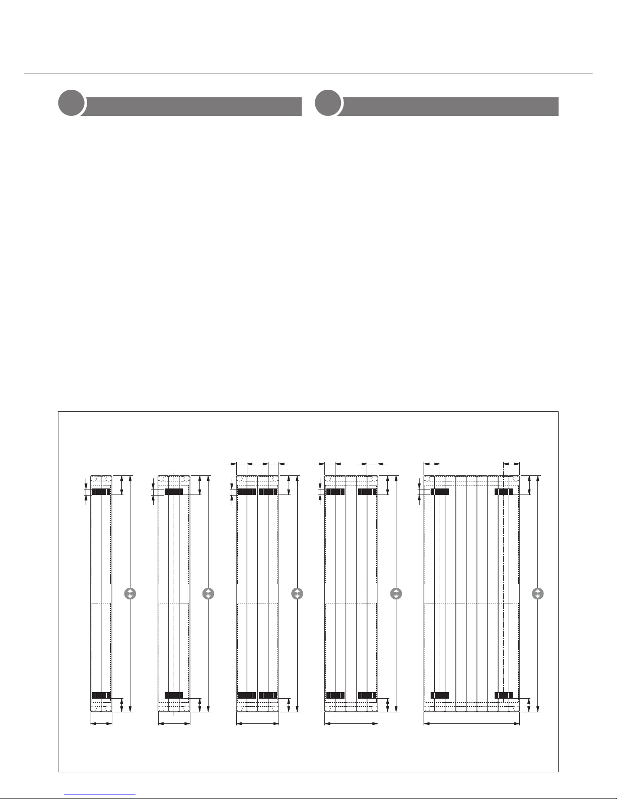
LASCHENAUFSCHWEISSBILD BRACKET / WELDING DIAGRAM
Achtung: Die zulässige Druckstufe (5.0 bzw 8.0 bar) und die zulässige Temperatur (110 °C) sind einzuhalten.
Important: The permissible pressure level (5.0 or 8.0 bar) and the permissible temperature (110 °C) must be adhered to.
142
1000, 1200, 1400, 1600, 1800, 2000, 2200
130
90
40
214
130
90
40
286
130
7171
90
40
358
13090
7171
40
BL 430 - 862
130
107107
90
40
1000, 1200, 1400, 1600, 1800, 2000, 2200
1000, 1200, 1400, 1600, 1800, 2000, 2200
1000, 1200, 1400, 1600, 1800, 2000, 2200
1000, 1200, 1400, 1600, 1800, 2000, 2200
BL 142 mm BL 214 mm BL 286 mm BL 358 mm BL 430 - 862 mm
Page 2
INSTRUCTIONS DE MONTAGE KONTEC KS
F
INSTRUKCJA MONTAŻU KONTEC KS
PL
ATTENTION: Pour une parfaite installation des radiateurs, il est primordial que la
fixation du radiateur soit effectuée de manière appropriée pour l’utilisation prévue
ET toute mauvaise utilisation prévisible. Un certain nombre d’éléments doivent être
pris en considération avant de réaliser l’installation comme le type et la qualité de
la fixation entre le radiateur et le mur, le type et l’état du mur lui-même ainsi que les
charges possibles après le montage.
SUSPENSIONS À UTILISER
Nota: Le KS n’existe qu’avec des pattes soudées.
• Pour monter le KS, utiliser uniquement les suspensions murales WA 10/20 et
WA 11/30.
• Utiliser la suspension murale WA 10/20 pour les longueurs 142 et 214.
• A partir d’une longueur de 286, utiliser la suspension murale WA 11/30.
CONSIGNES DE MONTAGE POUR KS
POUR L’UTILISATION DES SUSPENSIONS
MURALES WA 10/20, WA 11/30:
• Ouvrir la pellicule rétractable à l’avant des coins de protection.
• Retirer les coins de protection et découper avec précaution au cutter le carton qui
se trouve dessous au niveau des pattes de suspension.
• Fixer la suspension murale conformément au schéma de soudure des pattes.
• Accrocher le KS dans la suspension murale et fixer les éléments d’écartement sur les
pattes de suspension inférieures. Redresser le KS horizontalement et verticalement.
NOTA: Respecter impérativement la position prévue pour le raccord!!!
Les normes suivantes doivent être respectées lors du montage du radiateur:
• DIN 55900: Pulvérisation dans les pièces humides
• VDI 2035: Prévention des dommages dans les installations avec systèmes de chauf-
fage à eau chaude
• DIN 18017 Partie 3: Ventilation des salles de bains et des toilettes sans fenêtres
• EN 14336: Système de chauffage dans les bâtiments, Installation et commissionne-
ment des systèmes de chauffage à eau
UWAGA: W celu zapewnienia prawidłowej instalacji grzejników ważne jest wykonanie mocowania grzejnika w sposób, który jest zgodny z przeznaczeniem grzejnika i w
sposób zapobiegający jego nieprawidłowemu użytkowaniu. Przed końcową instalacją
należy wziąć pod uwagę między innymi metodę mocowania grzejnika do ściany, rodzaj i stan ściany do której będzie mocowany grzejnik oraz wszystkie potencjalne siły
i obciążenia.
GRZEJNIKI Z PRZYSPAWANYMI Z TYŁU ZAWIESZKAMI
Wskazówka: KS dostępny jest jedynie w wersji z przyspawanymi zawieszkami.
• Do montażu KS należy używać wyłącznie zawieszek ściennych WA 10/20 oraz
WA 11/30.
• Przy szerokości 142 względnie 214 należy użyć zawieszek ściennych WA 10/20.
• Od szerokości 286 należy użyć zawieszki ściennej WA 11/30.
WSKAZÓWKI MONTAŻOWE DLA KS
• Naciąć folię na powierzchni czołowej narożników ochronnych.
• Usunąć narożniki i naciąć poniżej znajdujący się karton w obrębie zawieszek
• Montaż zawieszki ściennej na ścianie; WA10/20 przy szerokości 142 lub 214 mm a
WA11/30 przy szerokości 286-862 mm według rozmieszczenia zawieszek przyspawanych do grzejnika.
• Powiesić KS na zawieszce ściennej WA10/20 lub WA11/30 i zamocować element
dystansujący na dolnych zawieszkach.
• Wyrównać w poziomie i pionie grzejnik.
WSKAZÓWKA: Należy bezwzględnie przestrzegać podanej pozycji
podłączenia grzejnika do instalacji!!!
KSMA102A
INSTRUCTIONS DE MONTAGE POUR PANNEAU CHAUFFANT VERTICAL KONTEC TYPE KS
INSTRUKCJA MONTAŻU KONTEC WERSJA PIONOWA KS
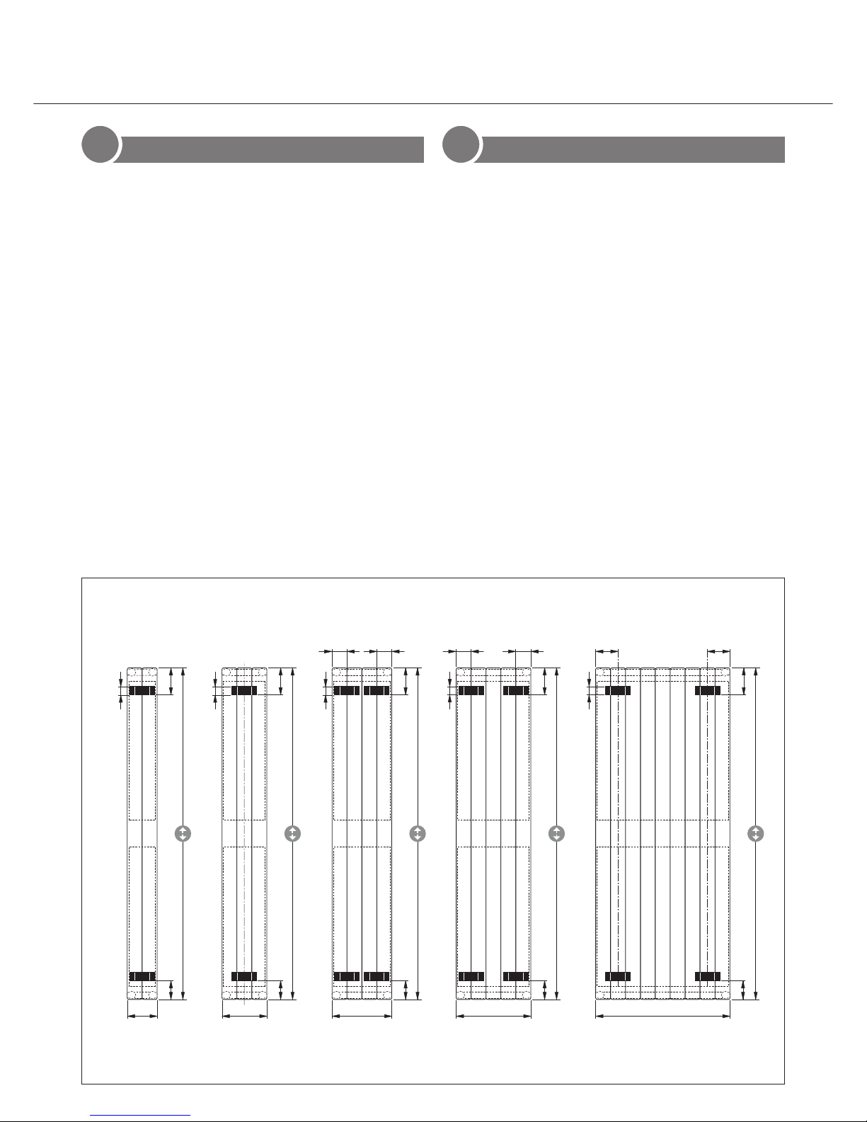
SCHÉMA DE SOUDURE DES PATTES / WIDOK MIEJSC PRZYSPAWANIA ZAWIESZEK
Attention: Respecter impérativement le palier de pression admissible (5.0 ou 8.0 bars) et la température admissible (110 °C).
UWAGA: Nie wolno przekraczać dopuszczalnych parametrów pracy grzejników: ciśnienia roboczego 5.0 bar lub 8.0 bar (wersja wysokociśnieniowa) oraz
maks. temperatury (110 °C).
142
1000, 1200, 1400, 1600, 1800, 2000, 2200
130
90
40
214
130
90
40
286
130
7171
90
40
358
13090
7171
40
BL 430 - 862
130
107107
90
40
1000, 1200, 1400, 1600, 1800, 2000, 2200
1000, 1200, 1400, 1600, 1800, 2000, 2200
1000, 1200, 1400, 1600, 1800, 2000, 2200
1000, 1200, 1400, 1600, 1800, 2000, 2200
BL 142 mm BL 214 mm BL 286 mm BL 358 mm BL 430 - 862 mm
 Loading...