

Page 1
Montageanleitung
Assembly manual
Cosmo STANDARD
Badheizkörper
Bathroom radiator
VOGEL&NOOT
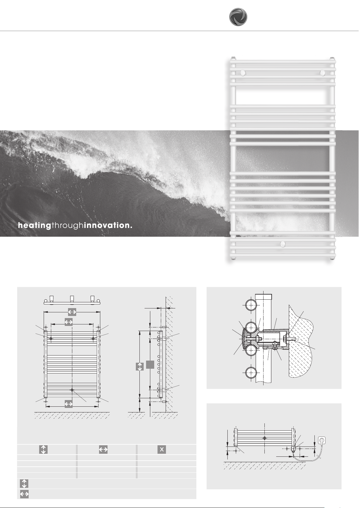
Abbildung 1 / Figure 1 / Schéma 1 / 1. ábra / Rysunek 1 / Obrázek 1
42 - 64
-150
IIII
AA
X
84
I
ACHTUNG! Heizkörperrückansicht • IMPORTANT! Heating element rear view
ATTENTION! Vue arrière du radiateur • FIGYELEM! A fűtőtest hátulnézete •
UWAGA! Widok grzejnika z tyłu • POZOR! pohled na topné těleso zezadu
[mm] [mm] [mm]
714 400, 500, 600, 750, 900 546
1134 400, 500, 600, 750, 900 966
1470 400, 500, 600, 750, 900 1302
1764 400, 500, 600, 750, 900 1596
Bauhöhe / Height / encom. en hauteur / magasság / Wysokość / konstrukční výška
- 40
B
I
150
min.
40 - 50 40 - 50
Abbildung 2 / Figure 2 / Schéma 2 / 2. ábra / Rysunek 2 / Obrázek 2
9
2
1
A
3
5
6
8
4
7
B
Abbildung 3 / Figure 3 / Schéma 3 / 3. ábra / Rysunek 3 / Obrázek 3
•
40 - 50
I
63 - 73
I
~18
T
Baulänge / Width / longueur hors tout / hossz / Szerokość / Konstrukční délka
DSLNWMAP0A
Page 2
Montageanleitung (D)
Installation/Montage Badheizkörper Cosmo STANDARD
ACHTUNG! Bei der Montage von Heizkörpern ist zu beachten, dass die Befestigung von
Heizkörpern so dimensioniert wird, dass sie für die bestimmungsgemäße Verwendung und
vorhersehbarer Fehlanwendung geeignet ist. Hierbei sind insbesondere die Verbindung
mit dem Baukörper sowie dessen Beschaffenheit, die Geeignetheit des Montagezubehöres
und die möglichen Belastungen nach erfolgter Montage zu prüfen.
Die Installation und Inbetriebnahme Ihres Badheizkörpers ist von einer zugelassenen Fachfi rma durchzuführen. Bei der Installation sind die einschlägigen Normen bzw. die nationalen elektrotechnischen Sicherheitsvorschriften, wie ÖVE- und VDE-Bestimmungen zu
beachten.
Unter Berücksichtigung der geometrischen Maße des Heizkörpers und der Anschlusselemente (Ventile, Verschraubungen) - siehe (Abb. 1) - ist die Verrohrung vorzubereiten. Wir
empfehlen, einen seitlichen Mindestabstand zum Heizkörper von 100 mm einzuhalten. Dabei ist Nachfolgendes zu berücksichtigen:
Wird eine Elektroheizpatrone nicht verwendet, werden für den Vorlauf- und Rücklaufanschluss die 1/2“ Muffen II bzw I genutzt. Aus optischen Gründen wird für diese Produkte oft
der reitende Anschluss, d. h. Vorlauf unten, Rücklauf unten empfohlen.
Bei Verwendung einer Elektroheizpatrone kann diese direkt in eine der Muffen I eingedichtet werden, wenn eine der Muffen II für den Vorlauf genutzt wurde.
Für den Fall eines reitenden Hydraulikanschlusses, d. h. Vorlauf unten, Rücklauf unten muss
in eine der beiden 1/2“ Muffen I das verchromte T-Stück T eingedichtet
werden, in das neben dem hydraulischen Anschluss auch die Elektroheizpatrone eingedichtet werden kann (Abb. 3). Dabei sind die Hinweise der Montageanleitung für das PTCElektroheizelement zu beachten. Die Verwendung des Elektroheizelements muss im Zuge
der Erstmontage des Badheizkörpers berücksichtigt werden. Eine spätere Elektroheizpatronenmontage ist nur mehr mit großem Montageaufwand möglich.
Die nicht verwendeten Anschlüsse mit den beigepackten Stopfen verschließen, wobei in
eine der beiden Muffen II die 1/2“ Entlüftung zu montieren ist.
WANDMONTAGE:
Anreißen, Bohren der Löcher A - Bohrer Ø10 - und Setzen der Dübel entsprechend den
Aufhängungsmaßen - (Abb. 1).
Befestigung der oberen Wandfüße 5 und waagrechtes Ausrichten derselben, wobei die
versenkten Langlochbohrungen 4 in den Wandfüßen nach unten stehen müssen. Dabei
sollen die Wandmontageschrauben 6 mit Beilagescheiben in der Mitte der Langlöcher der
Wandfüße montiert werden. Festziehen des unteren Montagestutzens 2 und Klemmteil 1
zwischen den horizontalen Rohren des Heizkörpers mit der Kreuzschlitzschraube 3 (Abb.
1 u. 2).
Aufstecken des unteren Wandfußes B auf den Montagestutzen 2 und mit Linsenkopfschraube 7 befestigen (dient als Distanzierung - vertikales Ausrichten).
Wandmontage des Heizkörpers: Die oberen Montagestutzen 2 werden in die Wandfüße 5
gesteckt und mittels Linsenkopfschraube 7 miteinander verbunden, Heizkörper mit Klemmteil 1 und Kreuzschlitzschraube 3 befestigen, Abdeckkappen 8 aufstecken (Abb. 1 u. 2).
Durch das versenkte Langloch im Wandfuß kann der Wandabstand variiert werden. Dies gilt
auch für den unteren Wandfuß zur vertikalen Ausrichtung des Heizkörpers.
Verstellmöglichkeiten der Wandfüße in Bauhöhenrichtung ist durch das Langloch 9 im
Wandfuß gegeben, sollten die hydraulischen Anschlüsse nicht genau passen.
Heizkörper hydraulisch anschließen.
Heizkörperbeschreibung
Die eleganten Badheizkörper sind geeignet für Warmwasserzentralheizungen mit max. Betriebstemperatur von 110 °C und max. Betriebsüberdruck von 10 bar.
Der gleichbleibende hohe Qualitätsstandard unterliegt einer laufenden Eigen- und Fremdüberwachung.
Nacharbeiten am Heizkörper (z.B. Schweißarbeiten) durch den Kunden sind nicht erlaubt.
Die Badheizkörper können auch mit einer Elektrozusatzheizung ausgestattet werden, wobei
die nachfolgenden Empfehlungen einzuhalten sind:
Heizkörperdimension
Baulänge x Bauhöhe
[mm]
400 x 714
400 x 1134
400 x 1470
400 x 1764
500 x 714
500 x 1134
500 x 1470
500 x 1764
Die hydraulische Leistungsregelung - Raumtemperaturregelung - erfolgt bei den Badheizkörpern durch ein extern montiertes Heizkörperthermostatventil.
PTC-heizelement
[W] bei 60 °C
300
300
300
300
300
300
600
600 x 714
600 x 1134
600 x 1470
600 x 1764
750 x 714
750 x 1134
750 x 1470
750 x 1764
900 x 714
900 x 1134
900 x 1470
900 x 1764
300
300
600
600
300
600
600
600
300
600
600
900
Das Wandmontagekonzept ist ein auf fertige Wände konzipiertes System.
Bedienung und Pflege
Die Badheizkörper sind hochwertige Produkte, die nicht nur der Raumheizung dienen, sondern die auch zur Trocknung von Handtüchern geeignet sind. Daher ist zu beachten, dass
sie heiße Oberfl ächen besitzen. Es dürfen nur Textilien, die mit Wasser gewaschen wurden,
getrocknet werden.
Selbstverständlich ist es unzulässig, diesen Heizkörper als Kletter- oder Sportgerät zu benutzen.
Zur Reinigung der Heizkörperoberfl ächen sind schonende, nicht scheuernde Reinigungsmittel zu verwenden.
Für den Fall des Elektroheizungsbetriebes muss die Heizwasserausdehnung immer bis zum
Expansionsgefäß gewährleistet sein, z. B. durch Öffnen des Rücklaufventiles. Um Wärmeverschleppungen in das Heizungsnetz zu vermeiden, wird in diesem Fall empfohlen, das
Thermostatventil zu schließen. Selbstverständlich darf die Elektroheizung nur in Betrieb genommen werden, wenn der Heizkörper komplett mit Heizungswasser gefüllt ist.
Wird der Heizkörper elektrisch betrieben, darf er aus sicherheitstechnischen Gründen nicht
komplett abgedeckt werden.
Assembly manual (GB)
Installation/Montage of bathroom heating element Cosmo STANDARD
ATTENTION! For the correct installation of radiators it is essential that the fi xing of the radi-
ator is carried out in such a way that it is suitable for intended use AND predictable misuse.
A number of elements need to be taken into consideration including the fi xing method
used to secure the radiator to the wall, the type and condition of the wall itself, and any
additional potential forces or weights, prior to fi nalising installation.
The installation and startup of your bathroom heating element must be performed by an
authorized installation company. The applicable standards and national electrotechnical
safety regulations such as the ÖVE and VDE regulations must be observed for installation.
The piping must be prepared in consideration of the geometric dimensions of the heating
element and the connection elements (valves, screw connections) – see (Fig. 1). We recommend maintaining a space of at least 100 mm on the sides of the heating element. Please
also note the following:
If an electrical heating cartridge is not used, the 1/2“ tapping II and I are used for the supply and return connection. To improve the appearance of the installed unit, connection is
often recommended with the fl ow and return connected at the bottom 2 tapping‘s I + I.
When using an electrical heating cartridge, this can be sealed directly into one of the tapping I, if one of the tapping II is used for the supply connection. In the case of a straddling
hydraulic connection, that is, supply below, return below, the chromed T-piece T must be
sealed into one of the two 1/2“ tapping. The electrical heating cartridge can then also be
sealed into the T-piece T in addition to the hydraulic connection (Fig. 3). The installation
instructions for the PTC electroheating element must be observed. The use of the electrical
heating element must be considered when installing the bath heating element for the fi rst
time. Subsequent installation of the electrical heating cartridge is only possible with great
diffi culty.
Close the unused connections with the plugs supplied, whereby the 1/2“ air bleed must be
installed in one of the two tapping II.
WALL INSTALLATION:
Marking, drilling of the holes A – drill diameter 10 – and placement of the pins according
to the mounting dimensions (Fig. 1).
Fastening of the top wall feet 5 and horizontal alignment of these feet, whereby the sunken
oblong holes 4 in the wall feet must face downward. The wall mounting screws 6 must be
mounted in the center of the oblong holes of the wall feet with shims. Tighten the lower
mounting connector 2 and clamping piece 1 between the horizontal pipes of the heating
element with the Phillips screw 3 (Fig. 1 and 2).
Attach the lower wall foot B to the mounting connector 2 and fasten it with the tallow-drop
screw 7 (serves as spacer – vertical alignment).
Wall mounting of the heating element: Insert the top mounting connectors 2 into the wall
feet 5 and connect them together with tallow-drop screws 7, fasten the heating element
with clamping piece 1 and Phillips screw 3, attach the end caps 8 (Fig. 1 and 2). The distance to the wall can be varied with the sunken oblong hole in the wall foot. This also applies
to the lower wall foot for vertical alignment of the heating element.
Oblong hole 9 in the wall foot offers vertical adjustment options for the wall feet in case the
hydraulic connections do not fi t exactly.
Hydraulically connect the heating element.
Heating element description
The elegant bathroom heating elements are suitable for central warm water heating with a
max. operating temperature of 110 °C and max. operating overpressure of 10 bar. The consistently high quality standard is subject to continuous internal and third-party monitoring.
Alterations to the heating element (e.g. welding work) by the customer are not
permitted.
The bathroom heating elements can also be equipped with supplemental electrical heating,
whereby the following recommendations should be observed:
Heating Element
Dimensions [mm]
Width x Height
400 x 714
400 x 1134
400 x 1470
400 x 1764
500 x 714
500 x 1134
500 x 1470
500 x 1764
The hydraulic output regulation – room temperature regulation – for the bathroom heating
elements is performed with an externally installed heating element thermostat valve.
PTC-
Electrical heating
[W] at 60 °C
300
300
300
300
300
300
600
600 x 714
600 x 1134
600 x 1470
600 x 1764
750 x 714
750 x 1134
750 x 1470
750 x 1764
900 x 714
900 x 1134
900 x 1470
900 x 1764
300
300
600
600
300
600
600
600
300
600
600
900
The wall mounting concept is a system designed for fi nished walls.
Operation and care
The bathroom heating elements are high-quality products that serve not only to heat the
room, but are also suitable for drying of hand towels. It is therefore important to note that
they have hot surfaces. Only textiles that have been washed in water may be dried.
Naturally, it is not permitted to use the heating elements as climbing objects or for games.
Use gentle, non-abrasive cleaning agents to clean the heating element surfaces.
When using the supplemental electrical heating, hot water expansion into the expansion
tank must always be guaranteed, e.g. by opening the return valve. To prevent transmission
of heat to the heating network, closing of the thermostat valve is recommended in this case.
Naturally, the electrical heating may only be started when the heating element is completely
fi lled with heating water.
If the heating element is operated electrically, it must not be completely covered for safety
reasons.
Page 3
Montage d’emploi (F)
Installation / Montage du radiateur sèche-serviettes Cosmo STANDARD
ATTENTION! Pour une parfaite installation des radiateurs, il est primordial que la fi xation du
radiateur soit effectuée de manière appropriée pour l’utilisation prévue ET toute mauvaise
utilisation prévisible. Un certain nombre d’éléments doivent être pris en considération avant de
réaliser l’installation comme le type et la qualité de la fi xation entre le radiateur et le mur, le
type et l’état du mur lui-même ainsi que les charges possibles après le montage.
L‘installation et la mise en service de votre radiateur sèche-serviettes doivent être effectuées
par des professionnels agréés. Il faut veiller lors de l’installation aux normes en vigueur et aux
consignes de sécurité nationales en matière d’électrotechnique telles que les dispositions ÖVE
et VDE. Il importe de préparer la tuyauterie en fonction des mesures géométriques du chauffage et des éléments de raccordement (soupapes, vissages) – voir (schéma 1). Il est recommandé
de respecter une distance latérale minimale de 100 mm du chauffage. Lors de ce montage, il
faut en outre tenir compte des éléments suivants: Si aucune cartouche de chauffage électrique
n‘est employée, on utilisera les manchons 1/2“ II et I pour les raccords d‘alimentation et de retour. Pour des raisons d‘esthétique, on recommande souvent d‘employer à cet effet le raccord
„à cheval“, où l‘alimentation et le retour sont tous les deux situés en bas. Si une cartouche de
chauffage électrique est employée, il est possible d‘insérer cette dernière de façon étanche,
directement dans un des manchons I, dans le cas où l‘un des manchons II est utilisé pour
l‘alimentation. Dans le cas d‘un raccord hydraulique „à cheval“ (avec alimentation et retour
en bas), il faut insérer dans un des deux manchons 1/2“ le raccordement en T chromé T, dans
lequel la cartouche de chauffage électrique pourra être insérée de façon étanche à côté du
raccord hydraulique (schéma 3). Il convient également de respecter les indications contenues
dans les instructions de montage pour l’élément de chauffe électrique PTC. L’utilisation de
l’élément de chauffage électrique doit être prise en compte lors du premier montage du radiateur de salle de bains, étant donné que le montage ultérieur de cette cartouche represente un
lourd investissement en terme de temps et d‘effort. Obturer les raccords non utilisés avec les
bouchons livrés avec l‘ensemble, en tenant compte du fait que la purge 1/2“ doit être montée
dans un des deux manchons II.
MONTAGE MURAL :
Traçage et perçage des trous A – Perceuse Ø10 – et placement des chevilles conformément aux mesures de suspension - (schéma 1).
Fixation des montants muraux supérieurs 5 et ajustement horizontal de ces derniers, en
tenant compte que les perçages des trous oblongs chanfreinés 4 dans les montants muraux
doivent être dirigés vers le bas. De plus, les vis de montage mural 6 avec rondelles de
calage doivent être montées au centre des trous oblongs des montants. Serrer à fond avec
la vis cruciforme 3 la partie inférieure de l‘embout de montage 2 et la pièce de serrage 1
entre les tuyaux horizontaux du chauffage (schémas 1 et 2).
Emboîtement du montant mural inférieur B sur l‘embout de montage 2 et fi xation avec vis
à tête lentiforme 7 (sert à l‘écartement et à l‘ajustement vertical).
Montage mural du radiateur : les embouts de montage supérieurs 2 sont enfoncés dans
les montants muraux 5 et raccordés les uns aux autres par une vis à tête lentiforme 7. Fixer
alors le radiateur avec la pièce de serrage 1 et la vis cruciforme 3, puis placer les chapes
8 (schémas 1 et 2). La distance au mur peut être modifi ée au moyen du trou oblong
chanfreiné, ce qui vaut également dans le cas du montant mural inférieur lors d‘un ajustement vertical du radiateur. Possibilités de réglage des montants muraux par rapport à la
hauteur de l‘installation au moyen du trou oblong 9 dans le montant mural, dans le cas où
les raccordements hydrauliques ne s‘adaptent pas exactement.
Raccorder le radiateur à la conduite d‘eau.
Description du radiateur
Les élégants radiateurs sèche-serviettes sont adaptés à des systèmes de chauffage central
à eau chaude présentant une température de fonctionnement maximale de 110 °C et une
surpression de fonctionnement maximale de 10 bar.
Le standard élevé et constant de qualité est soumis à un contrôle permanent, interne comme externe. Le client n‘est pas habilité à effectuer des travaux de retouche (par ex. des
travaux de soudure) sur le radiateur.
Les radiateurs sèche-serviettes peuvent être également équipés d‘un chauffage électrique
d‘appoint, sachant que les recommandations suivantes doivent être alors respectées :
Dimensions du
radiateur [mm]
longueur hors tout x
encom. en hauteur
400 x 714
400 x 1134
400 x 1470
400 x 1764
500 x 714
500 x 1134
500 x 1470
500 x 1764
Dans le cas des radiateurs sèche-serviettes, la régulation de puissance hydraulique – régulation de la température ambiante – se fait au moyen d‘une soupape thermostatique montée
en externe.
Le concept de montage mural est un système conçu pour des parois fi nies.
PTC-
Chaffage électrique
[W] à 60 °C
300
300
300
300
300
300
600
600 x 714
600 x 1134
600 x 1470
600 x 1764
750 x 714
750 x 1134
750 x 1470
750 x 1764
900 x 714
900 x 1134
900 x 1470
900 x 1764
300
300
600
600
300
600
600
600
300
600
600
900
Utilisation et entretien
Les radiateurs sèche-serviettes sont des produits de haute qualité qui ne servent pas seulement à chauffer la pièce, mais aussi à sécher les serviettes de toilettes. Il faut prendre en
compte le fait que leurs surfaces sont très chaudes. Il ne faut utiliser que des textiles lavés
avec de l’eau et secs.
De toute évidence, ce radiateur ne doit pas être utilisé pour grimper ni faire de la gymnastique.
Pour nettoyer les surfaces des corps de chauffe, utiliser des produits nettoyants doux et
non abrasifs.
Si un chauffage électrique est utilisé, l‘extension d‘eau chaude doit être toujours assurée
jusqu‘au vase d‘expansion, en ouvrant par exemple la soupape de retour. Afi n d‘éviter des
entraînements de chaleur dans le réseau de chauffage, il est indiqué, dans ce cas, de fermer
la soupape thermostatique. Le chauffage électrique ne doit être évidemment mis en service
que lorsque le chauffage est complètement rempli d‘eau de chauffage.
Si le chauffage fonctionne à l‘énergie électrique, il ne doit pas, pour des raisons de sécurité,
être complètement recouvert.
Szerel ési útmutató (H)
A fürdőszobai fűtőtesték installálásá / szerelése Cosmo STANDARD
FIGYELEM! A fűtőtestek felszerelésénél ügyelni kell arra, hogy azok falfelületre történő
rögzítése oly módon történjék, hogy a rendeltetésszerű használat és az esetlegesen
előforduló, nem megfelelő használatból adódó nagyobb terheléseket is elviselje. Figyelembe kell venni a falfelület anyagát és azok fi zikai tulajdonságait, valamint az alkalmazott
rögzítési módot. A felszerelést követően végezzünk terhelési próbát, a lehetséges maximális igénybevételnek megfelelően.
Fürdőszobai fűtőtestének installálását és üzembe helyezését engedéllyel rendelkező szakembernek kell elvégeznie. A szerelésnél fi gyelembe kell venni az ide vonatkozó szabványokat, ill. nemzetközi elektrotechnikai biztonsági előírásokat (pl. az ÖVE- és VDE-rendelkezéseket).
A csövezést a fűtőtest és a csatlakozóelemek (szelepek, menetes kötések) geometriai méreteinek – lásd 1. ábra – fi gyelembe vételével kell előkészíteni. Javasoljuk, hogy a fűtőtest
oldalánál tartson be minimum 100 mm távolságot. Eközben a következőkre kell ügyelni:
Ha nem használnak elektromos fűtőpatront, akkor az előremenő és a visszatérőcsatlakozásra a I, ill. II jelű, 1/2“-os belső menetes csatlakozókat kell használni. A jobb
megjelenés érdekében ezeknél a termékeknél gyakran az alsó csatlakozást javasoljuk, ahol
is az előremenő és a visszatérő csatlakozó is alul található.
Elektromos fűtőpatron alkalmazása esetén azt közvetlenül az egyik I jelű csatlakozóba kell
tömítetten beszerelni, ha az előremenő bekötéséhez az egyik II jelű csatlakozót használják.
A fűtőcsövek alsó csatlakoztatása esetén - azaz előremenő alul, visszatérő alul – a kettő
közül az egyik 1/2“-os I jelű csatlakozóba tömítetten bele kell szerelni a krómozott T-idomot (T), amibe a csőcsatlakozó mellett az elektromos fűtőpatron is beszerelhető tömítéssel
együtt (3. ábra). Közben be kell tartani a PTC elektromos fűtőelem szerelési utasítását. Az
első szerelés folyamán fi gyelembe kell venni azt, hogy a készülékben elektromos fűtőelem
van. Az elektromos fűtőpatron későbbi beszerelése csak több szerelési munkával lehetséges. A nem használt csatlakozókat a mellékelt dugókkal le kell zárni. Az egyik II jelű
csatlakozóba 1/2“-os légtelenítőt kell szerelni.
FELSZERELÉS A FALRA:
A felfüggesztési méretek szerint rajzolja fel és fúrja ki az A jelű lyukakat 10 mm-es fúróval,
és helyezze be a tipliket a lyukakba (1. ábra).
Rögzítse fel a felső fali rögzitőelemeket (5) és állítsa be őket vízszintesen, közben a
rögzitőelemekben lévő besüllyesztett ovális lyukaknak (4) lefelé kell állniuk. A falra szereléshez szükséges, alátétekkel ellátott csavarokat (6) a rögzitőelemek ovális lyukainak
közepére kell szerelni. Húzza meg a kereszthornyos csavarral (3) az alsó szerelőcsonkot
(2) és a fűtőtest vízszintes csövei közötti szorítóelemet (1) (1. és 2. ábra). Dugja az alsó
rögzitőelemet (B) a szerelőcsonkra (2), majd rögzítse azt a lencsefejű csavarral (7) (távtartásra és függőleges beállításra szolgál).
A fűtőtest falra szerelése:
Dugja a felső szerelőcsonkokat (2) a rögzitőelemekbe (5), és kösse össze őket egymással a
lencsefejű csavarral (7). Rögzítse a fűtőtestet a szorítóelemmel (1) és a kereszthornyos csavarral (3), majd helyezze fel a fedőkupakokat (8) (1. és 2. ábra). A rögzitőelemben lévő süllyesztett ovális lyukkal a faltól való távolság változtatható. Ez az alsó, a fűtőtest függőleges
beállítására szolgáló rögzitőelemre is vonatkozik.
A rögzítőelemek magassági állítását az elemben lévő ovális lyuk (9) biztosítja arra az esetre,
ha a fűtőcsövek csatlakozói nem illeszkednének pontosan.
Végezze el a fűtőtest csatlakoztatását a fűtőcsövekre.
A fűtőtest ismertetése
Az elegáns fürdőszobai fűtőtest max. 110 °C üzemi hőmérsékletű és max. 10 bar üzemi
nyomású melegvizes központi fűtésekhez használható.
Az egyenletes és tartós minőségi színvonalat belső és külső ellenőrzéssel biztosítjuk.
Az ügyfél a fűtőtesten nem végezhet utómunkákat (pl. hegesztéseket).
A fürdőszobai fűtőtestek kiegészítő elektromos fűtőlemmel is elláthatók, a következő
javaslatokat azonban be kell tartani:
Fűtőtestméret
[mm]
hossz x magasság
400 x 714
400 x 1134
400 x 1470
400 x 1764
500 x 714
500 x 1134
500 x 1470
500 x 1764
A vizes fűtési teljesítmény és a helyiséghőmérséklet szabályozása a fűtőtesteknél a külön
felszerelhető termosztáttal történik.
PTC elektromos
fűtőelem
[W] 60 °C esetén
300
300
300
300
300
300
600
600 x 714
600 x 1134
600 x 1470
600 x 1764
750 x 714
750 x 1134
750 x 1470
750 x 1764
900 x 714
900 x 1134
900 x 1470
900 x 1764
300
300
600
600
300
600
600
600
300
600
600
900
A falra való felszerelési koncepció kész falra való felszerelésre készült rendszert jelent.
Kezelés és ápolás
A fürdőszobai fűtőtestek olyan értékes termékek, amelyek nem csak helyiségfűtésre szolgálnak, hanem törülközők szárítására is alkalmasak. Ezért ügyelni kell arra, hogy forró felülettel
rendelkeznek. Csak vízzel mosható textíliákat szabad szárítani.
Magától értetődik, hogy a fűtőtestet mászókának vagy tornaszernek nem szabad használni.
A fűtőtest felületének tisztításához kímélő, nem súroló hatású tisztítószert kell használni.
Elektromos fűtési üzemmód esetén a fűtővíz tágulását (pl. a visszatérő szelep kinyitásával)
mindig egészen a tágulási tartályig biztosítani kell.
A hőnek a fűtőrendszerbe való áramlása elkerülése érdekében azt javasoljuk, hogy ilyen
esetben zárja el a termosztát-szelepet. Az elektromos fűtés természetesen csak akkor kapcsolható be, ha a fűtőtest teljesen fel van töltve fűtővízzel.
Ha a fűtőtest elektromos üzemmódban működik, akkor azt biztonsági okokból nem szabad
teljesen letakarni.
Page 4

Instrukcja montazu (PL)
Instalacja i montaż łazienkowych Cosmo STANDARD
UWAGA! W celu zapewnienia prawidłowej instalacji grzejników ważne jest wykonanie
mocowania grzejnika w sposób, który jest zgodny z przeznaczeniem grzejnika I w sposób
zapobiegający jego nieprawidłowemu użytkowaniu. Przed końcową instalacją należy wziąć
pod uwagę między innymi metodę mocowania grzejnika do ściany, rodzaj i stan ściany do
której będzie mocowany grzejnik oraz wszystkie potencjalne siły i obciążenia.
Instalacja i uruchomienie grzejnika łazienkowego owinno zostać wykonane przez uprawnioną
do tego fi rmę. Należy również uwzględnić obowiązujące normy i przepisy.
Podłączenie instalacji należy przygotować uwzględniając wymiary grzejnika oraz jego
podłączenia [Rys.1]. Zalecane jest utrzymanie minimalnej 100mm odległości boku grzejnika do najbliższej ściany.
WSKAZÓWKA
Jeśli nie używa się PTC-grzałki elektrycznej, do podłączenia przewodów zasilania i powrotu
stosuje się mufę I lub II o średnicy 1/2”. Ze względów estetycznych zaleca się zastosowanie
podłączeń od dołu grzejnika wykorzystując w obu przypadkach mufę I.
Grzałka elektryczna może zostać zamocowana bezpośrednio do mufy I, tylko wtedy, gdy
jedna z muf II zostanie wykorzystana jako zasilanie. W przypadku, gdy zasilanie i powrót
podłączy się od dołu grzejnika koniecznością staje się umieszczenie chromowanego trójnika T w jednej z muf I. Wtedy do chromowanego trójnika T, oprócz przewodu zasilającego
montowana jest grzałka elektryczna [Rys.3].
Należy przy tym przestrzegać wskazówek, zalecanych przez danego producenta grzałek,
dotyczących samego montażu grzałki elektrycznej. Poleca się również uwzględnienie
montażu grzałki elektrycznej w przyszłości, poprzez użycie chromowanego trójnika T już w
trakcie montażu grzejnika (wyklucza to użycie jednej z muf II jako zasilania). W przypadku
jeśli się tego nie wykona, późniejszy montaż grzałki elektrycznej możliwy będzie tylko przy
dużym nakładzie kosztów. Nie używane podłączenia należy zamknąć zaślepkami, przy czym
do jednej z muf II należy wmontować odpowietrznik o średnicy 1/2”.
MONTAŻ NA ŚCIANIE
Zgodnie z podanymi na rys.1 wymiarami, wyznaczyć punkty na ścianie, wywiercić otwory A wiertło Ø10 i umieścić w nich kołki rozporowe. Stopki ścienne 5 zamocować prostopadle do
ściany w pozycji A i B, a otwory 4 od spodu stopek ściennych. Wkręty 6 do kołków rozporowych do montażu ściennego zamontować w środku wzdłużnych otworów stopek ściennych 5.
Skręcenie elementu podpierającego 2 i części zaciskowej 1 pomiędzy poziomymi kolektorami
grzejnika odbywa się przy pomocy śruby 3 [Rys.1 i 2]. Przesuwanie elementu podpierającego
2 w stopce ściennej 5 i odpowiednie ustawienie śruby 7 służy do utrzymania pionu - równej
odległości grzejnika od ściany, na której został zamontowany. Dzięki otworowi wzdłużnemu 4 w
stopkach ściennych można zmieniać odległość od ściany.
MONTAŻ GRZEJNIKA
Elementy podpierające 2 umieszczone zostają w stopkach ściennych 5. Połączenie odbywa
sięprzy pomocy śruby 7. Ustalona zostaje tym samym odległość grzejnika od ściany. Grzejnik mocuje się do zawieszeń elementem zaciskowym 1 i śrubą 3.
Po dokręceniu śruby 3 nałożyć maskującą nakładkę 8 [Rys.1 i 2]. W przypadku, gdy
podłączenia do instalacji nie pasowałyby idealnie, istnieje możliwość regulacji wysokości
zawieszenia grzejnika. Odbywa się to dzięki wykonanemu w stopce ściennej podłużnemu
otworowi 9.
Po zawieszeniu grzejnika można podłączyć go do instalacji centralnego ogrzewania.
Opis grzejnika
Eleganckie grzejniki łazienkowe przeznaczone są do stosowania w wodnych instalacjach centralnego ogrzewania o maksymalnej temperaturze roboczej 110°C i maksymalnym ciśnieniu
roboczym 1,0 MPa.
Wysoki standard jakości jest sprawdzany i utrzymywany dzięki ciągłemu nadzorowi własnych
i zewnętrznych służb kontrolnych.
Niedopuszczalne jest podgrzewanie grzejnika np. palnikiem lub użycie lutownicy, a także
inne działania mogące powodować deformację grzejnika lub zniszczenie powłoki lakierniczej.
Wymiary grzejnika
[mm]
szerokość x
wysokość
400 x 714
400 x 1134
400 x 1470
400 x 1764
500 x 714
500 x 1134
500 x 1470
500 x 1764
Grzejniki łazienkowe przystosowane są do zastosowania PTC-grzałek elektrycznych i wtedy
regulacja temperatury w pomieszczeniu odbywa się przy użyciu głowicy termostatycznej zamontowanej na zaworze grzejnikowym.
Idea montażu na ścianie pomyślana jest jako system przeznaczony dla gotowych ścian.
PTC-grzałka
elektryczna
[W] przy 60 °C
300
300
300
300
300
300
600
600 x 714
600 x 1134
600 x 1470
600 x 1764
750 x 714
750 x 1134
750 x 1470
750 x 1764
900 x 714
900 x 1134
900 x 1470
900 x 1764
300
300
600
600
300
600
600
600
300
600
600
900
Obsługa i utrzymanie czystości
Grzejniki łazienkowe są produktami o wysokiej jakości służącymi nie tylko do ogrzewania
pomieszczeń, ale i do suszenia ręczników. Z tego też względu nie należy zapominać, że
grzejniki posiadają gorące powierzchnie.
Nie zezwala się natomiast na używanie grzejników do innych celów, jak np. drabinki do
ćwiczeń.
Do czyszczenia powierzchni grzejników należy stosować środki o łagodnym działaniu,
nie uszkadzających powierzchni.
W razie użycia grzałki elektrycznej, przyrost objętości wody musi być skompensowany
poprzez otwarcie zaworu powrotnego. Zaleca się także zamknięcie głowicy termostatycznej
na zasilaniu. Ogrzewanie elektryczne może zostać uruchomione tylko wtedy, gdy grzejnik
wypełniony został całkowicie wodą.
Jeżeli grzejnik działa jako elektryczny poprzez użycie grzałki elektrycznej, to ze względów
technicznych oraz bezpieczeństwa nie może być całkowicie zakryty.
Montážní návod (CZ)
Instalace / montáž koupelnových topných těles Cosmo STANDARD
POZOR! Pro správnou instalaci otopných těles je nezbytné, aby upevnění otopných těles
bylo provedeno způsobem odpovídajícím jejich určení a předvídatelnému zneužití. Proto
se při montáži každého otopného tělesa musí zvolit vhodný typ upevňovacího prvku, který
zohledňuje možné zatížení otopných těles, konstrukci stěny, stavební materiál a kvalitu
stěny.
Instalaci a uvedení vašeho koupelnového topného tělesa do provozu musí provést
oprávněná odborná fi rma. Při instalaci je nutno dodržet příslušné normy, příp. národní elektrotechnické bezpečnostní předpisy jako jsou např. ÖVE a VDE nařízení.
Se zřetelem ke geometrickým rozměrům topného tělesa a připojovacím prvků (ventily,
šroubení) – viz (obrázek 1) – je třeba připravit propojovací trubky. Doporučujeme dodržet
boční minimální odstup k topnému tělesu 100 mm. Přitom je třeba vzít v úvahu následující
podrobnosti:
Jestliže se nepoužije elektrická topná vložka, budou použity pro připojení vstupní a vratná
voda hrdla 1/2“ II, resp. I. Z optických důvodů se doporučuje pro tyto produkty často jednostranné připojení, to znamená výstupní voda i vratná voda dole.
Použije-li se elektrická topná vložka, je možno ji připojit s těsněním přímo do jednoho z
hrdel I, pokud bylo některé z hrdel II použito pro výstupní vodu. Pro případ jednostranného
hydraulického propojení, to znamená výstupní voda i vratná voda dole, je třeba do jednoho
z obou hrdel 1/2“ I připojit s těsněním pochromovaný T-kus T, do kterého je možno vedle
hydraulické přípojky připojit také elektrickou topnou vložku (obrázek 3). Přitom je třeba
dodržovat pokyny návodu pro montáž elektrického topného článku. Během prvních měsíců
musí být zohledněno použití elektrického článku. Pozdější montáž elektrické topné vložky
je totiž potom možná již jen s velkými montážními náklady.
Nepoužité přípojky se uzavřou zátkami, jež jsou součástí dodávky, přičemž do jednoho z
obou hrdel II se musí namontovat odvzdušnění 1/2“.
NÁSTĚNNÁ MONTÁŽ:
Narýsujte a vrtákem Ø10 mm vyvrtejte otvory A a uložte hmoždinky podle závěsných rozměrů
- (obrázek 1).
Upevněte horní nástěnné patky 5 a vyrovnejte je do vodorovné polohy, přičemž musejí vyvrtané podélné otvory 4 v nástěnných patkách směřovat směrem dolů. Přitom se mají šrouby
pro nástěnnou montáž 6 s podložkami namontovat uprostřed podélných otvorů nástěnných
patek. Dolní montážní opěrku 2 a upínací součást 1 utáhněte mezi horizontálními trubkami
topného tělesa s použitím šroubu s křížovou hlavou 3 (obrázky 1 a 2).
Na montážní opěrku 2 nasa_te dolní nástěnnou patku B a upevněte ji šroubem s čočkovou
hlavou 7 (slouží jako zajištění vzdálenosti – vertikální vyrovnání). Nástěnná montáž topného
tělesa: Horní montážní opěrky 2 se zasunou do nástěnných patek 5 a navzájem spojí pomocí šroubu s čočkovou hlavou 7, topná tělesa se upevní upínací součástí 1 a šroubem s
křížovou hlavou 3 (obrázky 1 a 2).
Pomocí vyvrtaného podélného otvoru v nástěnné patce je možno měnit vzdálenost topného tělesa od stěny. Totéž platí pro dolní nástěnnou patku pro vertikální vyrovnání topného
tělesa.
Pokud by hydraulické propojení přesně nesouhlasilo, je možno nástěnné patky přestavovat
výškovým směrem pomocí podélného otvoru 9 v nástěnné patce.
Hydraulicky připojit topné těleso.
Popis topněho tělesa
Elegantní koupelnová topná tělesa jsou vhodná pro ústřední teplovodní vytápění s maximální provozní teplotou 110 °C a maximálním provozním přetlakem 10 bar. Konstantně vysoká standardní kvalita je zajišťována průběžné vlastní kontrolou i kontrolou odběratele.
Dodatečné práce na topných tělesech (např. svařovací práce) prováděné zákazníkem nejsou
dovoleny.
Koupelnová topná tělesa je možno vybavit elektrickým přídavným ohřevem, přičemž je nutno dodržovat následující doporučení:
Rozměr topného
tělesa [mm]
Konstrukční délka x
konstrukční výška
400 x 714
400 x 1134
400 x 1470
400 x 1764
500 x 714
500 x 1134
500 x 1470
500 x 1764
Hydraulická regulace výkonu – regulace teploty místnosti – se provádí u koupelnových topných těles externě namontovaným termostatickým ventilem pro topná tělesa.
PTC-Elektrický
topný
článek
[W] při 60 °C
300
300
300
300
300
300
600
600 x 714
600 x 1134
600 x 1470
600 x 1764
750 x 714
750 x 1134
750 x 1470
750 x 1764
900 x 714
900 x 1134
900 x 1470
900 x 1764
300
300
600
600
300
600
600
600
300
600
600
900
Koncepce nástěnné montáže spočívá v systému navrženém na připravené stěny.
Obsluha a ošetřování
Koupelnová topná tělesa jsou vysoce hodnotné výrobky, které neslouží pouze pro vytápění
místnosti, nýbrž jsou vhodné rovněž pro sušení ručníků. Proto je nutno si uvědomit, že mají
horké povrchy. Je možné sušit pouze textilie, které byly vyprány ve
vodě.
Samozřejmě je nepřípustné používat tato topná tělesa jako přístroj pro šplhání nebo k
provádění sportu.
Pro čištění povrchů topných těles je třeba používat šetrné, neabrazivní čistící prostředky.
Použije-li se topné těleso pro elektrické vytápění, musí být vždy zajištěna expanze topné
vody až k expanzní nádobě, např. otevřením zpětného ventilu. Aby se zamezilo přenášení
tepla do otopné sítě, doporučuje se v tomto případě zavřít termostatický ventil. Elektrické
vytápění se smí samozřejmě uvést do provozu výhradně tehdy, když jsou otopná tělesa
kompletně naplněna topnou vodou.
Pokud se topné těleso ohřívá elektricky, nesmí být z bezpečnostně technických důvodů celé
kompletně zakryto.
Page 5

Instrucciones de montaje (ES)
Instalación i montaje de radiadores de baño Cosmo STANDARD
ATENCIÓN! Para instalar correctamente los radiadores es esencial que la fi jación del radia-
dor se realice de un modo apropiado para el uso previsto Y el mal uso predecible. Hay que
tener en cuenta una serie de elementos, entre ellos el método de fi jación utilizado para
asegurar el radiador a la pared, el tipo y el estado de la pared y cualquier otra fuerza o peso
posibles antes de fi nalizar la instalación.
La instalación y la puesta en funcionamiento de su radiador de baño deben ser realizadas
por una empresa especializada y autorizada. La instalación debe ajustarse a las normas
aplicables y a las disposiciones nacionales vigentes en materia de seguridad electrotécnica, por ejemplo a la normativa de la Asociación austríaca de electrotecnia (ÖVE) o de la
Asociación alemana de electrotecnia (VDE).
Prepare la colocación de los tubos teniendo en cuenta las dimensiones geométricas del
radiador y de los elementos de conexión (válvulas, atornilladuras) (ver Fig. 1). Es recomendable respetar una distancia lateral mínima al radiador de 100 mm.
Tenga presente además lo que sigue:
Si no se emplea un elemento de calefacción eléctrica, se utilizan para las conexiones de ida
y de retorno los manguitos II o I de 1/2”. Por razones de estética suele ser recomendable
utilizar para estos productos la conexión “a caballo”, es decir, ida abajo, retorno abajo.
Si se emplea un elemento de calefacción eléctrica se puede colocar directamente en uno
de los manguitos I en el caso de que se haya utilizado uno de los manguitos II para la ida.
Si se emplea una conexión hidráulica “a caballo”, es decir, ida abajo y retorno abajo, es necesario colocar en uno de los dos manguitos I de 1/2” la pieza en T T, en la cual se puede
colocar además de la conexión hidráulica también el elemento de calefacción eléctrica.
(Fig. 3). En esa operación se debe seguir las instrucciones de montaje del elemento de calefacción eléctrica PTC. Cuando se efectúe el primer montaje del radiador debe tenerse en
cuenta que se va a utilizar el elemento de calefacción eléctrica, ya que el montaje posterior
de ese elemento resultaría muy complejo. Cierre las conexiones no utilizadas mediante los
tapones incluidos, montando en uno de los manguitos II la salida de aire de 1/2”.
MONTAJE EN LA PARED:
Marque y practique los orifi cios A con una broca del 10 y coloque las clavijas con arreglo a
las medidas deseadas para montar el radiador en la pared (Fig. 1).
Fije los pies de pared superiores 5 y colóquelos en la posición correcta en sentido horizontal, teniendo en cuenta que los orifi cios alargados rehundidos 4 tienen que quedar en los
pies de pared mirando hacia abajo. Para ello, coloque los tornillos 6 con arandelas en el
centro de los orifi cios alargados de los pies. Fije bien la tubuladura de montaje inferior 2
y la pieza de sujeción 1 entre los tubos horizontales del radiador mediante el tornillo con
ranura en cruz 3 (Fig. 1 y 2).
Introduzca el pie de pared inferior B en la tubuladura de montaje 2 y únalos mediante el
tornillo alomado 7 (sirve para el distanciamiento y la correcta colocación vertical).
Para montar el radiador en la pared introduzca las tubuladuras de montaje superiores 2 en
los pies de pared 5 y únalos mediante el tornillo alomado 7. A continuación fi je el radiador
mediante la pieza de sujeción 1 y el tornillo con ranura en cruz 3 y coloque las caperuzas 8
(Fig. 1 y 2). Mediante el orifi cio alargado rehundido del pie de pared se puede modifi car la
distancia a la pared. Del mismo modo, el pie de pared inferior permite colocar el radiador
en la posición correcta en sentido vertical.
El orifi cio alargado 9 del pie de pared ofrece la posibilidad de modifi car la colocación de
los pies de pared en sentido vertical, en el caso de que las conexiones hidráulicas no quedasen en la posición exacta deseada.
A continuación efectúe la conexión hidráulica del radiador.
Descripción del radiador
Nuestros elegantes radiadores de baño son idóneos para sistemas de calefacción central
por agua caliente con una temperatura máxima de servicio de 110 °C y una presión máxima
de servicio de 10 bar.
Su alto nivel de calidad está sometido a una constante supervisión tanto propia como externa. Queda prohibida toda modifi cación del radiador por el cliente (p. ej. mediante soldaduras adicionales).
Los radiadores de baño pueden ir equipados también con un sistema adicional de calefacción eléctrica, para lo cual es necesario cumplir las siguientes recomendaciones:
Dimensiones del
radiador [en mm]
Ancho x alto
400 x 714
400 x 1134
400 x 1470
400 x 1764
500 x 714
500 x 1134
500 x 1470
500 x 1764
La regulación hidráulica del funcionamiento –basada en la temperatura ambiente–se efectúa en los radiadores de baño mediante una válvula de termostato de radiador montada
externamente.
El sistema de montaje en la pared está pensado para paredes ya terminadas.
Elemento de
calefacción
eléctrica PTC
[en W] a 60 °C
300
300
300
300
300
300
600
600 x 714
600 x 1134
600 x 1470
600 x 1764
750 x 714
750 x 1134
750 x 1470
750 x 1764
900 x 714
900 x 1134
900 x 1470
900 x 1764
300
300
600
600
300
600
600
600
300
600
600
900
Manejo y mantenimiento
Nuestros radiadores de baño son productos de alta calidad destinados no sólo a calentar
el cuarto de baño, sino que también resultan idóneos para el secado de toallas. Por ello se
debe tener en cuenta que sus superfi cies están calientes. Únicamente se debe secar en ellos
productos textiles que hayan sido lavados con agua.
Lógicamente, no está permitido subirse a los radiadores ni utilizarlos como aparatos de
gimnasio.
Para limpiar las superfi cies del radiador se debe emplear productos suaves y no abrasivos.
Si se emplea el sistema de calefacción eléctrica es necesario asegurarse de que el agua
pueda expandirse siempre hasta el tanque de expansión, p. ej. abriendo para ello la válvula
de retorno. A fi n de evitar el arrastre de calor a la red de calefacción es recomendable cerrar
en ese caso la válvula del termostato. Como es lógico, la calefacción eléctrica sólo se debe
poner en funcionamiento cuando el radiador esté completamente lleno de agua.
Por razones de seguridad, cuando el radiador esté funcionando en modo eléctrico no se
debe cubrir totalmente.
Istruzioni per il montaggio (I)
Installazione/montaggio del radiatore Cosmo STANDARD
ATTENZIONE! Durante il montaggio dei radiatori, occorre accertarsi che il fi ssaggio degli
stessi sia dimensionato in modo idoneo, ovvero tale da far fronte sia all‘utilizzo previsto
dell‘elemento riscaldante, sia ai prevedibili utilizzi scorretti e non conformi alle prescrizioni. Occorre quindi verifi care accuratamente i seguenti fattori: effi cacia e tipologia del
collegamento del radiatore, idoneità degli accessori utilizzati per il montaggio, nonché i
possibili carichi che potrebbero andare a gravare sull‘elemento installato una volta avvenuto il montaggio.
L’installazione e la messa in servizio di questo radiatore scaldasalviette deve essere effettuata
da una ditta specializzata riconosciuta che dovrà attenersi alla normativa vigente in materia e
alle norme di sicurezza elettrotecniche applicate nella nazione di appartenenza.
Predisporre i tubi di collegamento tenendo conto delle dimensioni geometriche del radiatore e
degli elementi di raccordo (valvole, raccordi avvitati), vedi Fig. 1. Si consiglia di mantenere una
distanza laterale minima di 100 mm dal radiatore.
Considerare che:
utilizzando una cartuccia riscaldante elettrica, per l’allacciamento di mandata e ritorno si usano
i manicotti da 1/2” II e I. Per motivi estetici, per questi prodotti spesso si consiglia di ricorrere
ad un allacciamento a correre, vale a dire con mandata e ritorno in basso.
La cartuccia riscaldante elettrica può essere inserita a tenuta direttamente in uno dei manicotti
I, se uno dei manicotti II è già stato utilizzato per la mandata. Nel caso di allacciamento idraulico a correre, vale a dire con mandata e ritorno in basso, è necessario inserire a tenuta il raccordo a T cromato in uno dei due manicotti da 1/2” nel quale, oltre all’allacciamento idraulico, si
può inserire a tenuta anche la cartuccia di riscaldamento elettrica (Fig. 3). In tal caso seguire le
avvertenze contenute nelle istruzioni di montaggio dell’elemento riscaldante elettrico PTC.
Quando si monta per la prima volta il radiatore scaldasalviette, considerare il fatto che si utilizza l’elemento riscaldante elettrico, in quanto un montaggio successivo della cartuccia implicherebbe un dispendio considerevole.
Chiudere i raccordi non utilizzati con i tappi in dotazione, montando lo scarico aria da 1/2” in
uno dei due manicotti II.
MONTAGGIO A PARETE:
Tracciare, trapanare i fori A con punta da Ø10 e inserire i tasselli conformemente alle quote di
aggancio (Fig. 1).
Fissare i sostegni da parete superiori 5 e regolare orizzontalmente gli stessi, tenendo conto
che i fori oblunghi 4 ribassati devono essere rivolti verso il basso nei sostegni stessi. Montare le
viti 6 per il montaggio a parete con le relative rondelle al centro dei fori oblunghi dei sostegni
da parete. Serrare il raccordo di montaggio inferiore 2 e il fi ssaggio 1 tra i tubi orizzontali del
radiatore utilizzando la vite a intaglio 3 (Figg. 1 e 2).
Applicare il sostegno a parete inferiore B sul raccordo di montaggio 2 e fi ssarlo con la vite a
testa svasata 7 (serve come distanziale per la regolazione verticale).
Montaggio a parete del radiatore: applicare i raccordi di montaggio superiori 2 nei sostegni a
parete 5 e collegarli tra loro utilizzando la vite a testa svasata 7, fi ssare il radiatore con il fi ssaggio 1 e la vite a intaglio 3, applicare i tappi 8 (Figg. 1 e 2).
Il foro oblungo ribassato presente nel sostegno a parete può servire per modifi care la distanza
dalla parete. Lo stesso vale anche per il sostegno a parete inferiore, utilizzabile per la regolazione verticale del radiatore.
Se si nota che gli allacciamenti idraulici non si adattano perfettamente alla posizione del radiatore, è possibile spostare e regolare i sostegni da parete utilizzando il foro oblungo 9.
Effettuare l’allacciamento idraulico del radiatore.
Descrizione del radiatore
Questi eleganti radiatori scaldasalviette sono idonei per sistemi di riscaldamento centralizzato ad acqua calda con temperatura massima di esercizio di 110 °C e sovrapressione
massima di esercizio di 10 bar.
Lo standard di qualità invariabilmente elevato è garantito dai controlli eseguiti continuamente sia internamente che ad opera di enti esterni. Il cliente non è autorizzato ad effettuare
lavori successivi sul radiatore, come ad esempio interventi di saldatura.
I radiatori scaldasalviette possono essere provvisti anche di un sistema di riscaldamento
aggiuntivo elettrico, nel qual caso è necessario attenersi ai seguenti suggerimenti:
Dimensione radiatore
[mm]
Lunghezza x altezza
400 x 714
400 x 1134
400 x 1470
400 x 1764
500 x 714
500 x 1134
500 x 1470
500 x 1764
La regolazione della portata idraulica e della temperatura ambiente dei radiatori scaldasalviette si effettua per mezzo di una valvola termostatica montata esternamente ai radiatori.
PTC Elemento
riscaldante elettrico
[W] a 60 °C
300
300
300
300
300
300
600
600 x 714
600 x 1134
600 x 1470
600 x 1764
750 x 714
750 x 1134
750 x 1470
750 x 1764
900 x 714
900 x 1134
900 x 1470
900 x 1764
300
300
600
600
300
600
600
600
300
600
600
900
Il sistema di montaggio a parete si basa su un sistema concepito per pareti fi nite.
Uso e manutenzione
I radiatori scaldasalviette sono prodotti pregiati che non servono solo a riscaldare l’ambiente,
ma anche ad asciugare salviette. Per questo motivo le sue superfi ci devono essere calde. Si
possono asciugare solo tessuti che sono stati lavati in acqua.
Chiaramente non è autorizzato l’uso del radiatore come scala o attrezzo sportivo.
Per la pulizia delle superfi ci del radiatore utilizzare detergenti delicati non abrasivi.
Nel caso in cui venga utilizzato il riscaldamento elettrico, l’espansione dell’acqua calda dovrà essere sempre garantita nel contenitore di espansione, ad esempio aprendo la valvola
di ritorno. Per evitare rallentamenti nella diffusione del calore nella rete di riscaldamento, si
consiglia in questo caso di chiudere la valvola termostatica.
Chiaramente il sistema di riscaldamento elettrico può essere attivato solo se il radiatore è
completamente pieno d’acqua calda.
Per motivi tecnici di sicurezza evitare di coprire completamente il radiatore quando funziona
a elettrico.
Page 6

Figura 1 / Figura 1 / Figura 1 / Рисунок 1 / Фигура 1 / Slika 1 Figura 2 / Figura 2 / Figura 2 / Рисунок 2 / Фигура 2 / Slika 2
42 - 64
-150
IIII
AA
A
X
B
84
I
- 40
B
ATENCIÓN! Vista trasera del radiador • ATTENZIONE! Visione posteriore del radiatore •
ATENTIE! Vedere din spate a corpului de incalzire • ВНИМАНИЕ! Вид нагревательного элемента
сзади • ВНИМАНИЕ! Изглед отзад на радиатора • POZOR! Pogled s hrbtne strani • POZOR!
Stražnja strana radiatora
[mm] [mm] [mm]
714 400, 500, 600, 750, 900 546
1134 400, 500, 600, 750, 900 966
1470 400, 500, 600, 750, 900 1302
1764 400, 500, 600, 750, 900 1596
altura / altezza / inaltime / монтажная высота / Монтажна височина / višina / ukupna visina
I
150
min.
40 - 50 40 - 50
9
2
1
5
3
6
8
4
7
Figura 2 / Figura 2 / Figura 2 / Рисунок 2 / Фигура 2 / Slika 2
I
40 - 50
I
63 - 73
~18
T
anchura / lunghezza / lungime / монтажная длина / Монтажна дължина / širina / ukupna širina
Instructiuni de montare (RO)
Instalarea/montarea corpurilor de incalzire Cosmo STANDARD
ATENTIE! La montarea radiatoarelor este obligatoriu să se ţină cont de faptul că fi xarea
lor trebuie să fi e astfel executată încât să corespundă întrebuinţării radiatoarelor conform
destinaţiei lor şi chiar situaţiei previzibile în care acestea sunt utilizate în mod eronat. În
acest sens, trebuie verifi cate după efectuarea montajului, în mod special, racordul cu peretele construcţiei, precum şi structura acestuia, rezistenţa accesoriului de montaj şi posibilele solicitări asupra structurii construcţiei.
Instalarea si punerea in functiune a corpului dumneavoastra de incazit se va face de catre o fi rma specializata. Se vor avea in vedere normele corespunzatoare, respectiv normele de siguranta electrotehnice nationale. Avand in vedere dimensiunile geometrice ale corpului de incalzire
si ale elementelor de legatura (ventile, asambalari prin surub) - vezi fi gura 1 - se vor pregati
racordurile cu tevile instalatiei de incalzire centrale. Va recomandam sa pastrati o distanta minima laterala la corpul de incalzire de 100 mm. Se vor avea in vedere urmatoarele: Daca una
din unitatile electrice de incalzire nu se utilizeaza se vor utiliza pentru racordul aductiei de alimentare si cel de retur garniturile de etansare II respectiv I de 1/2”. Din considerente estetice
se recomanda pentru aceste produse adesea racordarea cu ajutorul unui element sub forma
de T (asa numitul “racord calare”) respectiv cu turul si returul jos. In cazul utilizarii unui singur
element electric de incalzire, acesta poate fi introdus direct intr-una din garniturile de etansare
I, atunci cand una din garniturile de etansare II este folosita pentru aductia de alimentare. In
cazul unui “racord hidraulic calare”, respectiv cu aductia de alimentare jos si returul tot jos
trebuie monatat etans intr-una din garniturile de etansare I de 1/2” elementul cromat in forma
de T, in care alaturi de racordul hidraulic se poate monta etans si elementul electric de incalzire
(fi g. 3). Pentru aceasta se vor avea in vedere indicatiile de montare ale elementului electric de
incalzire PTC. Posibilitatea utilizarii unui element electric de incalzire trebuie avuta in vedere
inca de la montarea initiala a corpului de incalzire. Montarea ulterioara a elementelor electrice
de incalzire este posibila numai cu eforturi mari din punct de vedere al i nstalatiei. Racordurile
care nu au fost utilizate se vor inchide cu ajutorul busoanelor puse la dispozitie. Intr-una din cele
doua garnituri de etansare II se va monta sistemul de aerisire de 1/2”.
MONTAREA PE PERETE:
Se marcheaza pozitia si se efectueaza gaurile A cu ajutorul burghiului de Ø10. Se aseaza diblurile conform schitei de pozitionare – fi g. 1. Se monteaza elementele de fi xare superioare 5 pe
perete si se pozitioneaza pe orizontala, astfel incat gaurile inecate alungite 4 din elementele
de fi xare pe perete sa fi e orientate in jos. Se fi xeaza surubul 6 de montare la perete cu saiba in
mijlocul gaurilor longitudinale alungite din elementele de fi xare la perete. Se fi xeaza stutul de
montare 2 de elementul de fi xare 1 cu ajutorul surubului cu slit in forma de cruce 3 de tevile orizonatale ale corpului de incalzire. (fi g. 1 si fi g. 2). Se monteaza elementul de fi xare la perete B
pe stutul de montare 2 cu ajutorul surubului cu cap semirotund 7 (pentru distantarea de perete
si pozitionarea verticala a corpului de incalzire). Montarea propriuzisa a corpului de incalzire pe
perete: Stuturile de fi xare superioare 2 se vor introduce in elementele de fi xare la perete 5 si se
vor fi xa cu ajutorul suruburilor cu cap semirotund 7. Corpul de incalzire se va fi xa cu elementul
de fi xare 1 si surubul cu slit in forma de cruce 3. Asamblarea se acopera cu elementele 8 (fi
si fi g. 2). Datorita orifi ciului inecat alungit de-a lungul elementului de fi xare la perete se poate
varia distanta la perete a corpului de incalzire. Acest lucru este valabil si pentru elementul de
fi xare de jos B pentru pozitionarea verticala a corpului de incalzire.
Elementele de fi xare la perete se pot de asemenea pozitiona in sus sau in jos datorita orifi ciilor alungite 9 din elementele de fi xare la perete, daca racordurile hidraulice nu se potrivesc
exact.
Se racordeaza corpul de incalzire din punct de vedere hidraulic.
g. 1
Descrierea corpurilor de incalzire
Corpurile de incalzire elegante pot fi folosite in cazul incalzirii centrale cu apa calda cu
temperatura maxima de lucru de 110 °C si suprapresiune de lucru maxima de 10 bari Standardul inalt de calitate depinde de supravegherea continua a procesului de fabricatie de
catre specialisti.
Nu sunt permise lucrari ulterioare (de exemplu lucrari de sudare) la corpul de incalzire efectuate de catre client.
Corpurile de incalzire pot fi prevazute si cu un sistem de incalzire electric suplimentar, respectand urmatoarele indicatii:
Dimensiunile
corpului de
incalzire [mm]
Lungime x Inaltime
400 x 714
400 x 1134
400 x 1470
400 x 1764
500 x 714
500 x 1134
500 x 1470
500 x 1764
Reglarea hidraulica a performantei – reglarea temperaturii camerei – se realizeaza in cazul
corpurilor de incalzire pentru baie cu ajutorul unui ventil termostat montat pe exterior.
Montarea pe perete a corpurilor de incalzire foloseste un sistem de montare conceput
pentru pereti deja existenti.
Element de
incalzire electric
PTC
[W] la 60 °C
300
300
300
300
300
300
600
600 x 714
600 x 1134
600 x 1470
600 x 1764
750 x 714
750 x 1134
750 x 1470
750 x 1764
900 x 714
900 x 1134
900 x 1470
900 x 1764
300
300
600
600
300
600
600
600
300
600
600
900
Deservire si ingrijire
Corpurile de incalzire sunt produse de calitate care nu folosesc numai la incalzirea camerei ci
pot fi folosite si pentru uscarea prosoapelor. De aceea trebuie avut in vedere ca au suprafete
fi erbinti. Se vor usca numai textile care au fost spalate cu apa.
Desigur este interzisa utilizarea corpurilor de incalzire ca spalier sau orice alt tip de aparat
sportiv.
Pentru curatarea suprafetelor corpului de incalzire nu se vor folosi substante agresive sau
care pot zgaria suprafetele.
Pentru cazul lucrului cu incalzire electrica trebuie asigurata dilatarea apei de incalzire intotdeauna pana la vasul de expansiune, de exemplu prin deschiderea ventilului de retur. Pentru
a evita transportul caldurii in reteaua centrala de incalzire se recomanda inchiderea ventilului
termostatului. Sistemul de incalzire electrica se va pune desigur in functiune numai atunci
cand corpul de incalzire este plin cu apa (respectiv lichid de incalzire).
Daca corpul de incalzire este incalzit electric nu este permis din motive de siguranta tehnica
ca el sa fi e complet acoperit.
Page 7

РУКОВОДСТВО ПО МОНТАЖУ (RU)
УСТАНОВКА И МОНТАЖ ОТОПИТЕЛЬНОГО РАДИАТОРА ДЛЯ ВАННОЙ Cosmo STANDARD
ВНИМАНИЕ! Для правильной установки радиаторов важно выполнить крепление
радиатора так, чтобы учитывалось его назначение И возможное неправильное
обращение. При этом, до завершения установки, нужно предусмотреть ряд моментов,
таких как способ крепления радиатора к стене, тип и состояние самой стены, а также
любые дополнительные потенциальные силы или массы.
Установка и ввод в
выполняться уполномоченной специализированной фирмой. При монтаже должны
соблюдаться соответствующие нормативы и национальные правила электробезопасности,
аналогичные стандартам ÖVE и VDE. Необходимо подготовить трубопроводы с учетом
геометрических размеров отопительного радиатора и соединительной арматуры ( вентили,
резьбовые соединения) - см. рис. 1. Рекомендуется обеспечить расстояние от боковых
сторон радиатора не менее
Если не применяется электрический нагревательный элемент, для подающего и возвратного
соединения используются муфты II или I размером 1/2“. Для улучшения внешнего вида
таких изделий часто используется нижнее подключение, т. е. рекомендуется и подача, и
возврат снизу. При использовании электрического нагревательного элемента его можно
установить на
В случае использования нижнего подключения воды, т. е. и подача, и возврат снизу, на
одну из двух муфт I размером 1/2“ должен быть установлен хромированный тройник T, к
которому вместе с подключением воды можно подключить электрический нагревательный
элемент
(рис. 3). При этом необходимо соблюдать указания по монтажу электрического
нагревательного элемента PTC. Использование электрического нагревательного элемента
должно быть предусмотрено в ходе выполнения первоначального монтажа отопительного
радиатора для ванной комнаты. В последующем дополнительная установка электрического
нагревательного элемента потребует значительных трудозатрат. Неиспользуемые
патрубки следует закрыть прилагающимися в комплекте заглушками, причем на одной
двух муфт II должен быть установлен клапан 1/2“ для удаления воздуха.
НАСТЕННЫЙ МОНТАЖ:
Разметьте, просверлите отверстия A сверлом Ø10 и установите дюбеля согласно
размерам подвески (рис. 1). Закрепите верхние настенные держатели 5 и выровняйте
их горизонтально, чтобы утопленные прорези 4 в настенных держателях были обращены
вниз. При этом винты настенного крепления 6
устанавливаться посередине прорезей в настенных держателях. Затяните нижнюю
монтажную опору 2 и зажим 1 между горизонтальными трубами отопительного радиатора
винтом с крестообразным шлицем 3 (рис. 1 и 2). Установите нижний настенный
держатель B на монтажную опору 2 и закрепите его винтом с полупотайной головкой 7
(служит распоркой для вертикального
радиатора. Верхние монтажные опоры 2 вставляются в настенные держатели 5 и
соединяются между собой посредством полупотайного винта 7, отопительный радиатор
закрепляется зажимом 1 и винтом с крестообразным шлицем 3, надевается защитный
колпачок 8 (рис. 1 и 2). Благодаря утопленной прорези в настенном держателе можно
изменять расстояние от стены. Это
которого осуществляется вертикальное выравнивание отопительного радиатора.
Возможность регулирования высоты монтажа обеспечивается благодаря прорези 9 в
настенном держателе, в случае если невозможно точно совместить соединения водяных
патрубков.
Подсоедините патрубки подачи и возврата воды.
эксплуатацию отопительных радиаторов для ванной комнаты должны
100 мм. При этом необходимо учитывать следующее.
уплотнение на одну из муфт I, если одна из муфт II используется для подачи.
из
с подкладочными шайбами должны
выравнивания). Настенный монтаж отопительного
относится также и к нижнему держателю, с помощью
ОПИСАНИЕ ОТОПИТЕЛЬНОГО РАДИАТОРА
Элегантные отопительные радиаторы для ванных предназначены для центрального
водяного отопления при максимальной рабочей температуре 110 °C и максимальном
рабочем давлении 10 бар. Неизменно высокие стандарты качества непрерывно
контролируются как внутри фирмы, так и сторонними наблюдателями.
Проведение дополнительных работ на отопительном радиаторе (например, сварочных
работ) собственными силами заказчика не допускается.
Отопительные радиаторы для ванных комнат
нагревательными элементами при условии выполнения следующих рекомендаций:
Размеры радиатора
Габаритная длина х
высотa
[mm]
400 x 714
400 x 1134
400 x 1470
400 x 1764
500 x 714
500 x 1134
500 x 1470
500 x 1764
Гидравлическое регулирование мощности – регулирование температуры в помещении осуществляется на отопительных радиаторах для ванных комнат посредством отдельно
устанавливаемых терморегулирующих клапанов.
Система настенного монтажа рассчитана на установку на готовые стены.
Электрический
нагревательный
РТС-элемент
[Ватт] при 60 º С
300
300
300
300
300
300
600
могут также оборудоваться электрическими
600 x 714
600 x 1134
600 x 1470
600 x 1764
750 x 714
750 x 1134
750 x 1470
750 x 1764
900 x 714
900 x 1134
900 x 1470
900 x 1764
300
300
600
600
300
600
600
600
300
600
600
900
ОБСЛУЖИВАНИЕ И УХОД
Отопительные радиаторы для ванных комнат представляют собой высококачественные
изделия, которые служат не только для отопления помещения, но и для сушки полотенец.
При этом нужно следить за тем, чтобы полотенца располагались на горячих поверхностях.
Сушить можно только текстильные изделия, выстиранные в воде.
Разумеется, использовать радиатор в качестве лестницы или спортивного снаряда
запрещено
Для очистки поверхностей отопительного радиатора следует использовать мягкие,
неабразивные чистящие средства.
В случае эксплуатации с электронагревателем должно быть обеспечено соединение линии
горячей воды с расширительным резервуаром, например, посредством открытия обратного
клапана. Во избежание утечки тепла в отопительную сеть в этом случае рекомендуется
закрыть терморегулирующий клапан. Разумеется, режим электронагрева можно включать
только тогда, когда отопительный радиатор полностью наполнен водой.
Если отопительный радиатор работает с электронагревом, по правилам техники
безопасности его нельзя закрывать снаружи.
.
УПЪТВАНЕ ЗА ИНСТАЛИРАНЕ (BG)
ИНСТАЛИРАНЕ / МОНТАЖ НА РАДИАТОР ЗА БАНЯ Cosmo STANDARD
ВНИМАНИЕ! При монтажа на отоплителните тела да се предвиди закрепването така,
че да е съобразено с използването по предназначение и предварително предвидимата
допълнителна употреба. Затова след монтажа трябва да се провери връзката със
стената, както и нейното качество, пригодността на крепежните елементи и възможните
натоварвания
Инсталирането и пускането в експлоатация на радиатора за баня трябва да се извърши от
оторизирана специализирана фирма. При инсталирането трябва да се вземат под внимание
съответните стандарти респ. националните наредби за електротехническа безопасност,
като наредбите на Австрийския съюз за електротехника (OVE) и Съюза на германските
електротехници (VDE).
Като вземат под внимание геометричните размери
елементи (вентили, винтови съединения) – виж (фиг. 1) – свързването на тръбите трябва да
се подготви предварително. Препоръчваме Ви да спазвате минимално разстояние встрани от
радиатора от 100 mm.
При това трябва да се вземе предвид следното: Ако не се използва електрическия нагревателен
патрон, за свързването на захранващия и отвеждащия
муфи ІІ респ. І. За постигане на по-добър външен вид на тези изделия често се препоръчва
свързване, при което захранващият тръбопровод е отдолу и отвеждащият тръбопровод е
отдолу. Ако се използва електрически нагревателен патрон, той може да бъде набит направо
в една от муфите І, когато
на свързване към водопровода със захранващ тръбопровод отдолу и отвеждащ тръбопровод
отдолу, в една от двете 1/2”-ови муфи І трябва да се набие хромираният Т-образен тръбен
съединител Т, в който освен връзката към водопровода може да се набие
нагревателен патрон (фиг. 3). При това трябва да се спазват указанията в инструкцията
за монтаж за електрическия нагревателен елемент РТС. Използването на електрическия
нагревателен елемент трябва да се вземе под внимание още в хода на първоначалния монтаж
на радиатора за баня. По-късен монтаж на електрическия нагревателен патрон е
но тогава се изискват много повече усилия и време за монтаж. Запушете неизползваните
връзки с приложените в опаковката тапи, като в една от двете муфи ІІ трябва да се монтира
1/2”-ов обезвъздушител.
СТЕНЕН МОНТАЖ:
Очертайте, пробийте отворите А – със свредло Ø10 – и поставете дюбели, като се съобразявате
с размерите
Закрепете горните крачета за стената 5 и ги изправете хоризонтално, като скритите
надлъжни отвори 4 в крачетата за стената трябва да останат надолу. Винтовете за монтаж
към стената 6 с регулиращите шайби трябва да се монтират в средата на надлъжните отвори
на крачетата за стената. Затегнете долната
хоризонталните тръби на радиатора с винт с кръстообразно гнездо 3 (фиг. 1 и 2). Поставете
долното краче за стената В на монтажната наставка 2 и го закрепете с винт със сфероцилиндрична глава 7 (служи за дистанциране – вертикално регулиране).
Монтаж за радиатора на стената: Поставете
за стената 5 и ги свържете помежду им с винт със сферо-цилиндрична глава 7, закрепете
радиатора със стягащата част 1 и винт с кръстообразно гнездо 3, поставете капачките 8
(фиг. 1 и 2). Посредством скрития надлъжен отвор в крачето за стената може да се променя
разстоянието до стената. Това важи и за долното краче за стената при вертикално регулиране
на радиатора. Ако хидравличните връзки не пасват точно, съществува възможност за
преместване на крачетата за стената на височината на монтажа чрез надлъжния отвор 9 в
крачетата за стената. Свържете радиатора към водопровода.
за окачване – (фиг. 1).
една от муфите ІІ се използва за захранващия тръбопровод. В случая
монтажна наставка 2 и затягащата част 1 между
на радиатора и присъединителните
тръбопровод се използват 1/2”-ови
и електрическият
възможен,
горните монтажни накрайници 2 в крачетата
ОПИСАНИЕ НА РАДИАТОРА
Елегантните радиатори за баня са подходящи за централно отопление с подаване на
топла вода с макс. работна температура от 110 °C и макс. работно свръхналягане от 10
бара.
Постоянният висок стандарт на качеството подлежи на непрекъснат собствен и външен
контрол. Не се разрешават допълнителни работи по радиатора (напр. заваряване) от
страна на клиентите.
Радиаторите
при което трябва да се спазват следните препоръки:
радиатора Дължина
Регулирането на хидравличната мощност – регулирането на околната температура при
радиаторите се осъществява чрез външно монтиран термостатен вентил на радиатора.
за баня могат да бъдат оборудвани с допълнителен електрически нагревател,
Размери на
x Височина
[mm]
400 x 714
400 x 1134
400 x 1470
400 x 1764
500 x 714
500 x 1134
500 x 1470
500 x 1764
Електронагревателен
елемент PTC
[W] при 60 °C
300
300
300
300
300
300
600
600 x 714
600 x 1134
600 x 1470
600 x 1764
750 x 714
750 x 1134
750 x 1470
750 x 1764
900 x 714
900 x 1134
900 x 1470
900 x 1764
300
300
600
600
300
600
600
600
300
600
600
900
Разработената система за монтаж на стена е предназначена за готови стени.
ИЗПОЛЗВАНЕ И ПОДДРЪЖКА
Радиаторите за баня са висококачествени изделия, които служат не само за отопление на
помещения, но са подходящи и за сушене на хавлиени кърпи. По тази причина трябва да
се съобразявате с това, че повърхността им е гореща. Могат да се сушат само текстилни
материи, които са изпрани с вода.
Естествено не
За почистване на повърхностите на радиаторите трябва да се употребяват щадящи, не
триещи почистващи препарати.
В случай на използване с електрически нагревател трябва да се осигури разширяването
на топлата вода до разширителния съд, например чрез отваряне на възвратния клапан. За
да се избегне отнемане на топлина от отоплителната мрежа в този случай, се препоръчва
термостатният вентил да се затваря. Разбира се включването на електрическия нагревател
трябва да се става само тогава, когато радиаторът е изцяло пълен с вода.
Когато радиаторът работи с електричество, за осигуряване на безопасността той не
трябва да
се допуска използването на радиатора като стълба или спортен уред.
бъде покриван изцяло.
Page 8

Navodila za namestitev (SLO)
Vgradnja/sestavljanje grelnega elementa za kopalnice Cosmo STANDARD
POZOR! Pri montaži grelnih teles je potrebno pravilno izbrati in pravilno dimenzionirati
ustrezen način pritrditve grelnih teles; način pritrditve mora namreč ustrezati tudi želenemu
načinu rabe grelnih teles. Prav posebej pa je potrebno paziti tudi na povezavo grelnih teles
s konstrukcijo zgradbe, na lastnosti konstrukcije zgradbe ter na ustreznost montažnega materiala (vijakov ipd.) glede na dano konstrukcijo zgradbe. Po opravljeni montaži je potrebno
preveriti tudi možne obremenitve.
Grelni element za kopalnico sme namestiti in zagnati le pooblaščeno instalacijsko podjetje.
Pri namestitvi upoštevajte ustrezne standarde in državne elektrotehnične varnostne predpise, na primer ÖVE in VDE.
Cevi morajo biti pripravljene v skladu z geometrijo grelnega elementa in povezovalnih
elementov (ventilov, vijakov) – glejte sliko 1. Na vsaki strani grelnega elementa naj ostane
vsaj 100 mm prostora.
Pazite tudi na naslednje:
Če ne boste uporabili električnega grelnega vložka, uporabite za dovod in odvod
polpalčna priključka II in I. Za boljši videz nameščenega izdelka priporočamo povezavo nad
priključnimi cevmi, tako da sta dovod in odvod pod izdelkom.
Če boste uporabili električni grelni vložek, ga priključite neposredno na enega od
priključkov I, če enega od priključkov II uporabljate kot dovod. Če želite uporabiti povezavo nad priključnimi cevmi, tako da sta dovod in odvod pod izdelkom, morate na enega
od dveh polpalčnih priključkov namestiti kromirani T-priključek. V tem primeru lahko v T-
priključek namestite tudi električni grelni vložek (slika 3).
Upoštevajte namestitvena navodila za električni grelni element PTC. Za uporabo električnega
grelnega vložka se odločite pred prvo namestitvijo grelnega elementa. Naknadna vgradnja
električnega grelnega vložka je zelo težavna.
Neuporabljene priključke zaprite s priloženimi čepi, v enega od priključkov II pa morate
namestiti še polpalčni priključek za odzračevanje.
NAMESTITEV NA ZID:
Označite in izvrtajte luknje A – premer vrtine 10 mm –, potem pa namestite zatiče v skladu
z dimenzijami namestitve (slika 1).
Pritrdite zgornje zidne nosilce 5 in jih vodoravno poravnajte, podolgovate poglobljene luknje 4 v nosilcih pa morajo biti obrnjene navzdol. Vijake za pritrditev na zid 6 s podložkami
namestite v sredino podolgovatih lukenj. S križnim vijakom 3 privijte spodnji pritrdilni
priključek 2 in spono 1 med vodoravni cevi grelnega elementa (slika 1 in 2).
Spodnji zidni nosilec B pritrdite na pritrdilni priključek 2 in ga privijte z vijakom s kupolasto
glavo 7 (služi kot distančnik za navpično poravnavo).
Pritrditev grelnega elementa na zid: Vstavite zgornje pritrdilne priključke 2 v zidne nosilce 5,
potem pa jih povežite z vijaki s kupolasto glavo 7. Potem pritrdite grelni element s spono
1 in križnim vijakom 3 ter pritrdite končne pokrovčke 8 (sliki 1 in 2). Razdaljo do zidu lahko
spreminjate s podolgovato luknjo v zidnem nosilcu. To velja tudi za spodnji zidni nosilec za
navpično poravnavo grelnih elementov.
Podolgovata luknja 9 v zidnem nosilcu omogoča navpično poravnavo zidnih nosilcev v
primeru, da se priključki ne prilegajo dobro.
Priključite priključke na grelni element.
Opis grelnega elementa
Elegantni grelni elementi za kopalnice so primerni za centralno ogrevanje s toplo vodo do
temperature 110 °C in pritiska 10 bar.
Konsistentno visoka kakovost se nenehno preverja s strani podjetja in tretjih oseb.
Spremembe grelnega elementa (npr. varjenje) s strani kupca niso dovoljene.
Grelne elemente za kopalnice je mogoče opremiti tudi z dodatnim električnim ogrevanjem,
pri čemer upoštevajte naslednja priporočila:
Ogrevalni element
Dimenzije [mm]
Širina x Višina
400 x 714
400 x 1134
400 x 1470
400 x 1764
500 x 714
500 x 1134
500 x 1470
500 x 1764
Regulacija vodnega ogrevanja (temperature) za kopalniške grelne elemente poteka prek
zunanjega termostatskega ventila.
PTC –Električno
ogrevanje
[W] pri 60 °C
300
300
300
300
300
300
600
600 x 714
600 x 1134
600 x 1470
600 x 1764
750 x 714
750 x 1134
750 x 1470
750 x 1764
900 x 714
900 x 1134
900 x 1470
900 x 1764
300
300
600
600
300
600
600
600
300
600
600
900
Pritrditev na zid je prilagojena za dokončno obdelane zidove.
Delovanje in nega
Grelni elementi za kopalnice so kakovostni izdelki, ki niso primerni le za ogrevanje sobe,
ampak omogočajo tudi sušenje brisač. Zaradi tega je pomembno povedati, da imajo vroče
površine. Iz tega razloga je dovoljeno le sušenje tkanin, ki so bile oprane v vodi.
Poleg tega je seveda prepovedana tudi uporaba grelnih elementov kot plezal ali igral.
Za čiščenje površin grelnega elementa uporabljajte le nežna čistila, ki ne praskajo.
Če uporabljate dodatno električno gretje, mora biti zagotovljen izhod za razširjanje vroče
vode, na primer skozi odprt povratni ventil. Da se prepreči prenos toplote v omrežje centralne kurjave, priporočamo, da v tem primeru zaprete termostatski ventil.
Seveda električnega gretja ne vključujte, dokler grelni element ni do konca napolnjen z
vodo.
Če grelni element deluje s pomočjo električnega grelnega vložka, ne sme biti popolnoma
pokrit zaradi varnostnih razlogov.
Uputa za montažu (HR)
Instalacija i montaža kupaonskog radijatora Cosmo STANDARD
POZOR! Pri montaži radijatora treba paziti da držači radijatora budu tako koncipirani, da
odgovaraju predviđenoj namjeni i da izdrže predvidivo nenamjensko korištenje. Ovdje treba posebice povjeriti vezu s građevinskom podlogom i njezine osobine, podesnost elemenata za montažu, te opteretivost nakon izvršene montaže.
Instalacija i prvo puštanje u rad vašeg kupaonskog radijatora mora izvesti ovlašteni instalater. Pri tome treba poštivati važeće standarde.
Instalaciju treba izvesti prema dimenzijama grijačeg elementa i vrsti priključnih elemenata
(ventili, priključni fi ting) – vidi (slika 1). Preporučujemo da se osigura slobodan prostor od
najmanje 100 mm sa svake strane radijatora. Molimo obratiti pažnju na slijedeće:
Ako se ne koristi električni grijač, za spajanje na polaz i povrat koriste se 1/2“ spojevi I i II. Iz
estetskih razloga preporuča se „jahači“ priključak, što znači polaz ispod, povrat ispod.
Kada se koristi električni grijač, isti se može ugraditi direktno u jedan od priključaka I, ako
se priključak II koristi za spajanje polaza. U slučaju izvođenja „jahačkog“ priključka (polaz
dolje, povrat dolje) u jedan od dva priključka treba ugraditi kromirani T-komad. U tom
slučaju se električni grijač može ugraditi u taj T-komad. T-komad je dodatak hidrauličkom
spoju (slika 3). Upotreba električnog grijača treba se uzeti u razmatranje prije prve ugradnje
kupaonskog radijatora. Naknadna instalacija električnog grijača iziskuje puno radova.
Nekorištene priključke treba zatvoriti isporučenim čepovima pri čemu 1/2“ odzračni pipac
mora biti instaliran na jednom od dva priključka II.
ZIDNA INSTALACIJA:
Označavanje, bušenje rupa A - promjer rupe Ø10 – i postavljanje tipli prema ugradbenim
mjerama (slika 1).
Postaviti gornji zidni držač 5 i element za horizontalno podešavanje tog držača pri čemu
uzdužni otvor 4 u zidnom nosaču mora biti okrenut prema dolje. Vijci za zidnu montažu 6
moraju biti montirani u sredini uzdužnog otvora zidnog nosača sa podložnim pločicama.
Pričvrstiti donji montažni podložak 2 i prihvatni element 1 između horizontalnih cijevi radijatora pomoću križnih vijaka 3 (slika 1 i 2).
Složiti donji zidni držač B sa montažnim podloškom 2 i pričvrstiti ih vijkom 7 (služi kao
odstojnik – vertikalno podešavanje).
Zidna montaža kupaonskog radijatora: Ubaciti gornji montažni podložak 2 u zidni držač 5
i spojiti ih zajedno vijkom 7. Pričvrstiti radijator priključnim elementom 1 i križnim vijcima 3
te zatvoriti završnom kapom 8 (slika 1 i 2). Preko uzdužnog otvora u zidnom nosaču može
se mijenjati udaljenost od zida. Podešavanje vertikale izvodi se takoder preko uzdužnog
otvora na donjem zidnom nosaču.
U slučaju da cijevni priključci ne odgovaraju u potpunosti, vertikalno podešavanje može se
izvršiti pomoću uzdužnog otvora 9 u zidnom nosaču.
Spojiti grijači element na cijevovod.
Opis radijatora
Elegantni kupaonski radijatori su grijači elementi namijenjeni centralnom toplovodnom grijanju sa maksimalnom radnom temp. Od 110° C i maksimalnim pritiskom od 10 bara.
Dosljedno se provodi visok standard kvalitete stalnim internim i vanjskim monitoringom.
Naknadni radovi na grijačem tijelu (npr. zavarivanje) nisu dozvoljeni korisnicima. Kupaonski grijači element može biti opremljen i dodatnim električnim grijanjem, pri čemu treba
poštivati sljedeće preporuke:
Dimenzija
Radijatora (mm)
Dužina x visina
400 x 714
400 x 1134
400 x 1470
400 x 1764
500 x 714
500 x 1134
500 x 1470
500 x 1764
Hidraulička regulacija – regulacija temperature prostorije – kod kupaonskog radijatora provodi se preko ugrađenog termostatskog radijatorskog ventila i termo glave.
PTC-Elektrićni
Grijać (W)
pri temperaturi
od 60°C
300
300
300
300
300
300
600
600 x 714
600 x 1134
600 x 1470
600 x 1764
750 x 714
750 x 1134
750 x 1470
750 x 1764
900 x 714
900 x 1134
900 x 1470
900 x 1764
300
300
600
600
300
600
600
600
300
600
600
900
Pribor za zidnu montažu prilagođen je završenim zidovima.
Rukovanje i održavanje
Kupaonski radijatori su visoko kvalitetni proizvodi koji nisu namijenjeni samo grijanju prostorija, već i sušenju ručnika. Stoga treba imati na umu njihove vruće površine.
Naravno, grijači element nije dozvoljeno koristiti kao ljestve ili za sportsku igru.
Za čišćenje njegovih površina treba upotrebljavati nježna, neabrazivna sredstva za čišćenje.
Kada se koristi dodatno električno grijanje mora biti osigurano širenje tople vode u ekspazivnu posudu., npr. otvaranjem ventila povrata. Da bi se spriječila transmisija topline u toplinsku mrežu, preporučuje se zatvaranje termostatskog ventila. Naravno, električno grijanje
smije se uključiti samo kada je grijači element potpuno napunjen vodom.
Ako se radijator zagrijava električno, ne smije biti potpuno prekriven iz sigurnonosnih razloga.
 Loading...