

Page 1
®
Adaptive architectural lighting systems
BoxRail® | 907 | Remote Power
Please read instructions in their entirety before proceeding with any part of the installation. This product must be installed in accordance with the applicable installation
code by a person familiar with the construction and operation of the product and the hazards involved. Consult a qualified electrician to ensure correct branch circuit rating.
To prevent electric shock, disconnect all power before installing or servicing product. Rated for use in dry and damp locations only. Retain instructions for future reference.
Technical Support: 707-996-9898
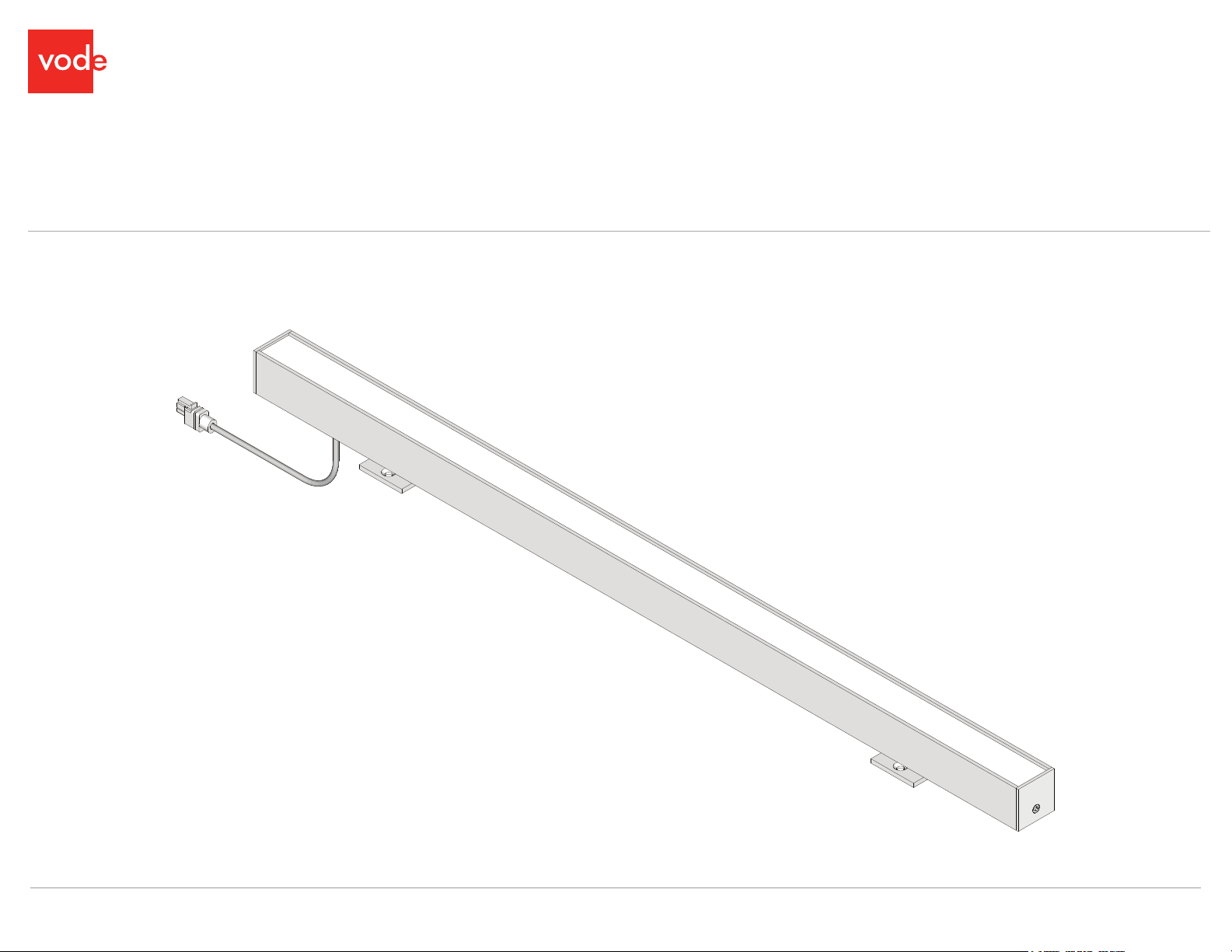
Installed View
BoxRail | 907 | Installation Guide | October 2018 | Rev A • 1
© 2018 Vode Lighting LLC. All rights reserved. | 21684 8th Street East, Suite 700, Sonoma, CA 95476 | 707.996.9898
Page 2
Fixed 1 (F1S)
- Page 4
BoxRail | 907
Parts DiagramTable of Contents
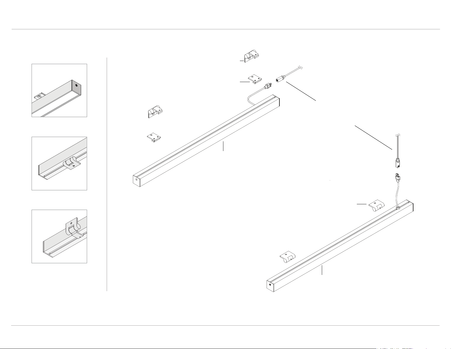
BK-907-BX-SR2-YY
Surface Mount 49° Rotating Bracket
BK-907-BX-S1-YY
Surface Mount Fixed Bracket
WRH-MWP-XX-M-18/2-YY
2-Conductor Wire Harness
(25’ standard)
907-BX-XX-...-YY
907 | BoxRail with Side Feed
Rotate 1 (R1B)
- Page 5
Rotate 2 (R2B)
- Page 6
BK-907-BX-SR1-YY
Surface Mount 203° Rotating Bracket
907-BX-XX-...-YY
907 | BoxRail with Back Feed
BoxRail | 907 | Installation Guide | October 2018 | Rev A • 2
© 2018 Vode Lighting LLC. All rights reserved. | 21684 8th Street East, Suite 700, Sonoma, CA 95476 | 707.996.9898
Page 3

Installation Instructions
To LED
BoxRail | 907
Install Remote Power Supply
IMPORTANT! Before installing power supply, turn off electricity at circuit box.
Install power supply housing to desired surface using screws (provided by others). Run
line voltage wiring into power housing through knockout and secure with 1/2" NPT fitting.
Ground housing by connecting ground/earth to green slot in the quick-connect. Connect
common/neutral to white slot in quick connect and line/hot to black slot in quick
disconnect.
Feed low voltage wire harness into remote power housing. Connect wire harness to
power supply using Red (+) and Black (-) leads. Leave approximately 1" of wire harness
hanging out of Micro J-Box or other hole.
DO NOT power on system until the installation is complete.
For remote power supply maximum distance or other wiring questions, please consult
Vode Driver Guide.
N
L
Line Voltage Connection
Quick connect provided for
line voltage connection
Conduit Fittings
(provided by others)
WRH-MWP-XX-M-18/2-YY
18 gauge, multi-strand
plenum rated wire harness
Fixture Orientation
Power feed comes out the bottom of the fixture (as shown) and is located 3” (76 mm)
in from the end of the fixture.
NOTE: For 85° optics, power feed is located on the left side of the fixture, when
facing the illuminated surface.
Fixed 1 (F1S)
Fixture wire harness comes out the
side of the fixture, approximately 3”
from the right end, as the light faces
away from the user. For the 85°
Asymmetric optics, the light will
always be emitted from the far side
of the wire harness.
Rotate 1 (R1B)
Fixture wire harness comes out the
bottom of the fixture, approximately
3” from the right end, as the light
faces away from the user. For the
85° Asymmetric optics, the light will
always be emitted from the far side
of the wire harness.
+
LED output 1
-
+
LED output 2
-
+
LEDcode
NTC
-
DO NOT USE
See Vode Driver Guide for wiring detail.
Example Only
Rotate 2 (R2S)
Fixture wire harness comes out the
side of the fixture, approximately 3”
from the right end, as the light faces
away from the user. For the 85°
Asymmetric optics, the light will
always be emitted from the far side
of the wire harness.
BoxRail | 907 | Installation Guide | October 2018 | Rev A • 3
© 2018 Vode Lighting LLC. All rights reserved. | 21684 8th Street East, Suite 700, Sonoma, CA 95476 | 707.996.9898
Page 4
Installation Instructions
BoxRail | 907
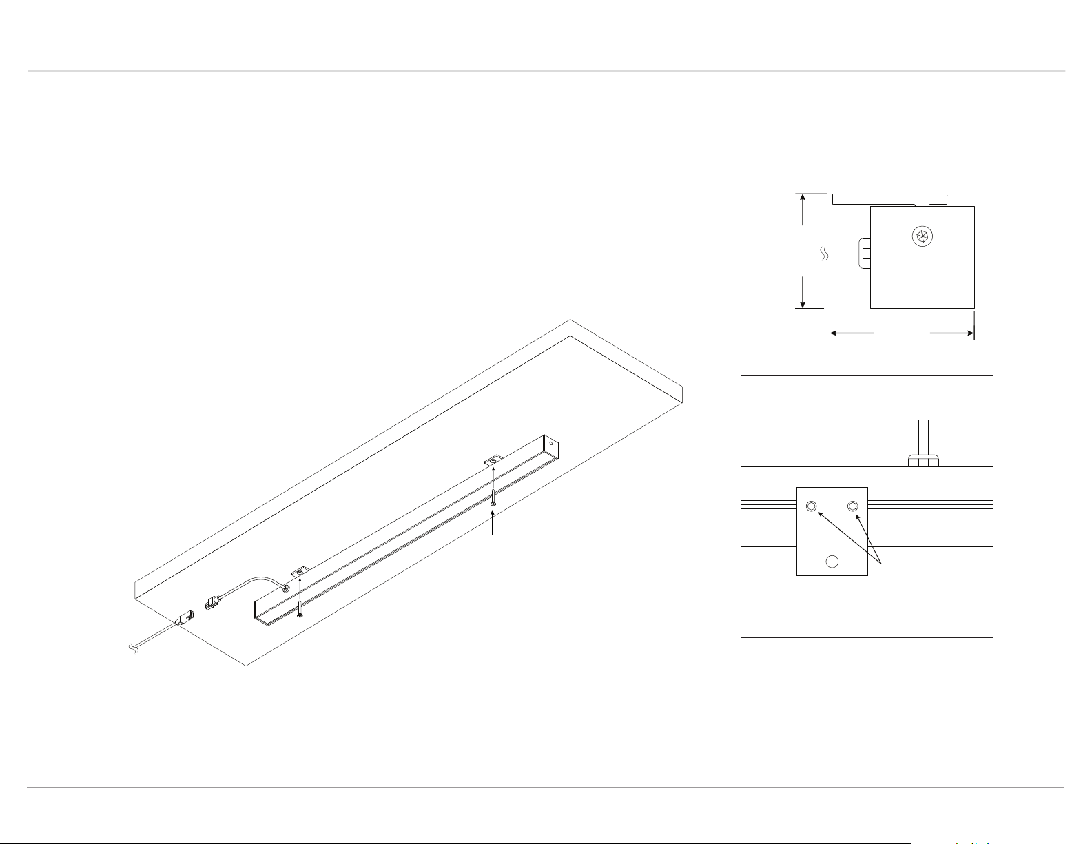
Fixed 1 (F1S)
Each rail is pre-installed with two adjustable mounting brackets that can be secured in
place using the provided set screws. It is recommended that they are positioned
approximately 3” in from the end. Vode recommends using the provided minimum spacing
measurements to ensure the fixture can install properly.
Using #8 flat head screws, provided by others, position fixture and screw to desired
mounting surface.
NOTE: Be careful with fixture orientation for the 85° Asymmetric Fixture. For 85° optics,
power feed is located on the left side of the fixture, when facing the illuminated surface.
See page 3 for more information.
Side View
Use these minimum measurements to ensure
your mounting location will be sufficient
1.28”
(33 mm)
1.6”
(42 mm)
Top View
Connect fixture to
provided Wire
Harness
use #8 screws
(provided by others)
BoxRail | 907 | Installation Guide | October 2018 | Rev A • 4
© 2018 Vode Lighting LLC. All rights reserved. | 21684 8th Street East, Suite 700, Sonoma, CA 95476 | 707.996.9898
Provided
5/64” (2 mm)
set screws
Page 5
Installation Instructions
BoxRail | 907
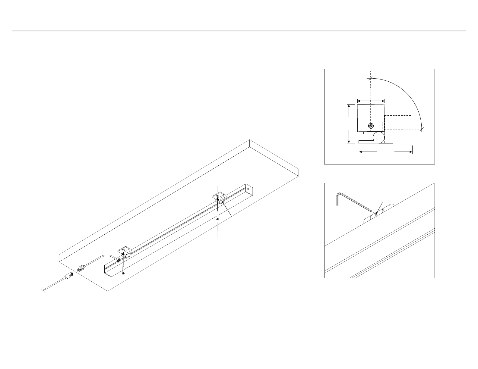
Rotate 1 (R1B)
Each rail is pre-installed with two adjustable mounting brackets that can be secured in
place using the provided set screws. It is recommended that they are positioned
approximately 3” in from the end. Vode recommends using the provided minimum spacing
measurements to ensure the fixture can install properly.
Rotate the bracket open to allow access to the mounting hole. Using #8 flat head screws,
provided by others, position fixture and screw to desired mounting surface. Rotate the
fixture into the desired position and use the provided set screws to lock in place.
NOTE: Be careful with fixture orientation for the 85° Asymmetric Fixture. For 85° optics,
power feed is located on the left side of the fixture, when facing the illuminated surface.
See page 3 for more information.
Provided
1/16” (1.5 mm)
set screw
Side View
Use these minimum measurements to ensure
your mounting location will be sufficient
1.14”
(29 mm)
1.6”
(41 mm)
2.22"
(56 mm)
Provided
1/16” (1.5 mm)
set screw
90°
Connect fixture to
provided wire
harness
use #8 screws
(provided by others)
BoxRail | 907 | Installation Guide | October 2018 | Rev A • 5
© 2018 Vode Lighting LLC. All rights reserved. | 21684 8th Street East, Suite 700, Sonoma, CA 95476 | 707.996.9898
Page 6
Installation Instructions
BoxRail | 907
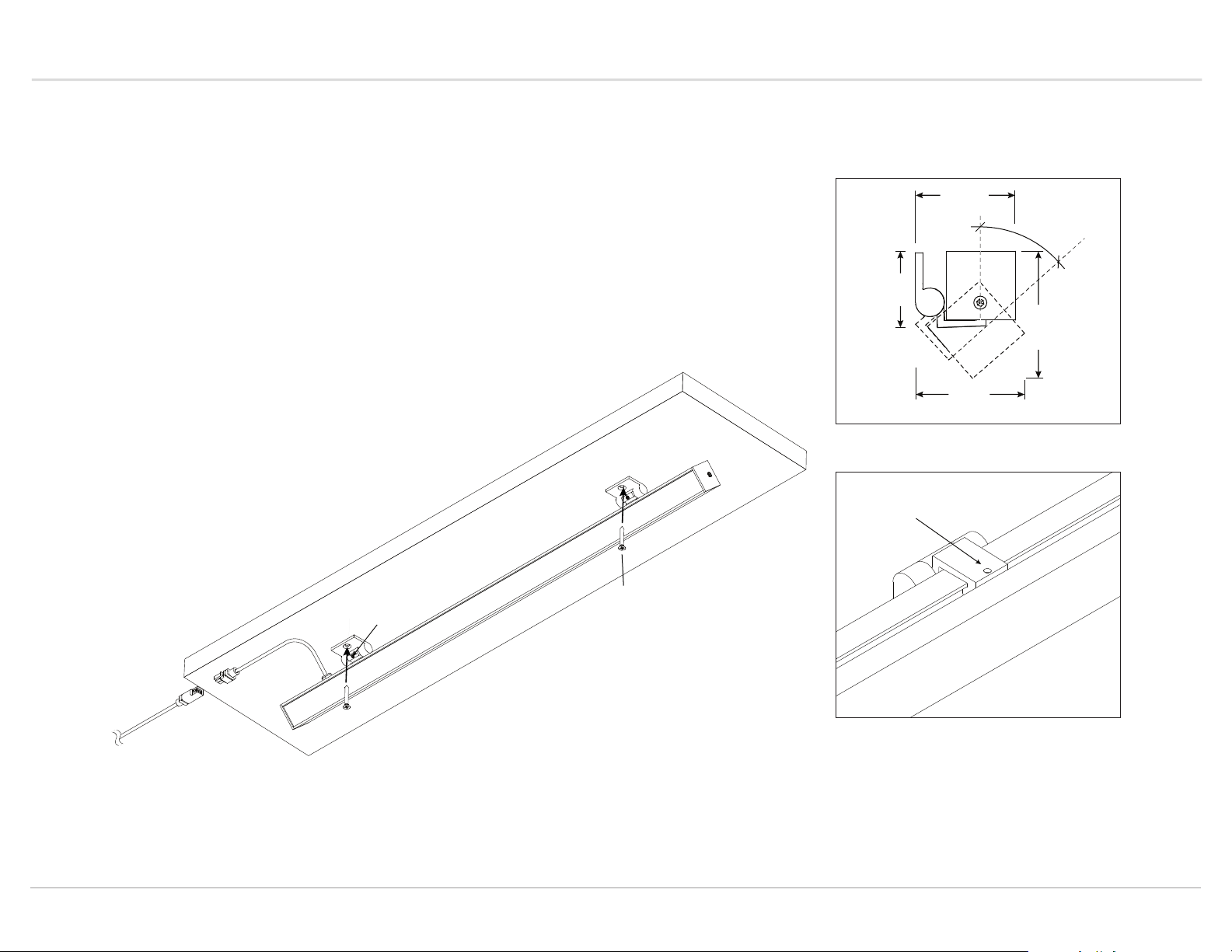
Rotate 2 (R2S)
Each rail is pre-installed with two adjustable mounting brackets that can be secured in
place using the provided set screws. It is recommended that they are positioned
approximately 3” in from the end. Vode recommends using the provided minimum spacing
measurements to ensure the fixture can install properly.
Rotate the bracket open to allow access to the mounting hole. Using #8 flat head screws,
provided by others, position fixture and screw to desired mounting surface. Rotate the
fixture into the desired position and use the provided set screws to lock in place.
NOTE: Be careful with fixture orientation for the 85° Asymmetric Fixture. For 85° optics,
power feed is located on the left side of the fixture, when facing the illuminated surface.
See page 3 for more information.
Side View
Use these minimum measurements to ensure
your mounting location will be sufficient
1.66"
(42 mm)
48°
1.27"
(32 mm)
2.1"
(53 mm)
1.81"
(46 mm)
Provided
1/16” (1.5 mm)
set screw
Connect fixture
to provided wire
harness
Provided
1/16” (1.5 mm)
set screw
BoxRail | 907 | Installation Guide | October 2018 | Rev A • 6
© 2018 Vode Lighting LLC. All rights reserved. | 21684 8th Street East, Suite 700, Sonoma, CA 95476 | 707.996.9898
use #8 screws
(provided by others)
Page 7
Appendix
BoxRail | 907
Trouble Shooting Guide
My fixture will not turn on:
Check all wiring is correct and all connections are fastened properly.
If all wiring is correct, remove fixture and connect it to a known working driver.
If the fixture lights up, then the problem is with the installed driver or wiring:
1) Check line voltage to driver is present.
2) Check driver wiring (see Vode Driver Guide for details) and check wiring to
fixture.
3) Check driver and dimming system are compatible (see Vode Dimmer
Guide and the dimmer manufacturer's website).
If fixture still doesn't light up, check that all dimming wires are installed
correctly. Reversed polarity on any driver will cause the entire system to not
work, (see Vode Driver Guide for wiring details).
The fixture is not dimming properly:
Check all wiring is correct and all connections are fastened properly.
Check driver wiring (see Vode Driver Guide for details). Make sure driver is
compatible with dimming controls (see Vode Dimmer Guide and the dimmer
manufacturer's website).
Important Notes
-
Listed to UL standards for damp location by a Nationally Recognized Testing
Laboratory (NRTL) recognized by OSHA
-
Operating Temperature: 32°F to 104°F (0°C to 40°C).
-
Input Voltage: 120v - 277v, 50/60hz.
-
Power Type: Class 2 (<60v) constant current driver.
-
Dimming curve is factory preset to linear. Logarithmic is available upon
-
request. See Vode Driver Guide for specific details and wiring diagram.
-
Unless specified, one driver per rail will be supplied.
-
5 Year Limited Warranty. All material and component parts manufactured by
Vode are guaranteed to be free from defects of material and/or workmanship
for a period of 5 years from date of sale. Product must be installed according
to Vode installation instructions and accepted trade practices. Power supplies
and other auxiliary equipment is not covered under Vode warranty but may be
covered by separate OEM warranty.
Remote Driver Distance
Note: All Vode remote drivers come in a 1/16” (0.8mm) formed steel, zinc chromate
plated power supply housing with six (6) knockouts for 1/2" NPT fittings. Power
supply housing dimensions: 1.9” (48.3 mm) x 1.9” (48.3 mm) x 24.5” (622.3 mm)
For any help with installation or technical information,
contact Vode Tech Service at 707-996-9898.
© 2018 Vode Lighting LLC. All rights reserved. | 21684 8th Street East, Suite 700, Sonoma, CA 95476 | 707.996.9898
EldoLED
Philips
OSRAM
Lutron
For other wiring questions, see Vode Driver Guide.
BoxRail | 907 | Installation Guide | October 2018 | Rev A • 7
Remote Distance Driver
72’ (21.9 m)
32’ (9.8 m)
16’ (4.88 m)
Zipper board: Standard / Low Output: 30' (9.14 m),
High Output: 15' (4.57 m)
Button board: Standard / Low Output: 15' (4.57 m)
High Output: 10' (3.05 m)
 Loading...