

Vodavi Starplus Triad 1/2/3, Starplus Triad 1, Starplus Triad 2, Starplus Triad 3 Installation Manual
Page 1

Feature Package 3
TRIAD 1/2/3
Installation
a new dimension in business communications
Page 2

STARPLUS
Installation Manual
TM
Triad 1/2/3
TM
Part Number: 8050-12 Issue 3.2 - March 2001
Page 3
Issue Re lease Date Changes
28-99
Feature Package 2 {FP2} enhancements have been added.
Manualcontentcontains extensive revisions.
2.1 12-99 Manual content has been revised.
3 5-00 Manual content has been reformatted.
3.1 8-00 Manual content has been revised to clarify Feature Package 3.
3.2 3-01 Manual content has been revised for correctness and clarity.
LIFE SUPPORTAPPLIC ATIONS POLICY
VODAVI Communications Sy stems products are notauthorized for and should not
be used within Life Support applications. Life Support systems are equipment
intended to support or sustain life and whose failure to perform when properly used
in accordance with instructions provided can be reasonably expected to result in
significant personal injury or death.
VODAVI Communications Systems warranty is limited to replacement of defective
components and does not co ver i njur y to per son s or p roper ty or o ther
consequential damages.
Copyright ©2001 VODAVI Technology,Inc.
This material is copyrighted by VODAVI Technology, Inc., and may be duplicated by
Authorized Dealers only. Any unauthorized reproductions, use or disclosure of this
material, or any part thereof, is strictly prohibited and is a violation of the Copyright
Laws of the UnitedStates (17 U.S.C.Section 101et. seq.).
VODAVI reserves the right to make changes in spec ifications at any tim e and without
notice. Theinformation furnished by VODAVIin this materialis believed to be accurate
and reliable, but is not warranted to be true in all cases.
STARPLUS
and
TRIAD™
AllRights Reserved
are R egistered trademarks of VODAVI Technology, Inc.
mlj/200 1
Page 4

Contents
1Introduction
Regulatory Information (U.S.A. ) ............................ .. .. ..... .. .... .. ......................... 1-3
Telephone Company Notification ............................... .. .. .... .. .... .. ..... .. .... 1-3
Incidence of Harm .......................... .. .. .... .. .... .. .... .. .. ..... .. .... .. .... .. ................... 1-4
Changes in Servic e ................ .. .. ..... .. .... .. .. .... .. .... .. ..... .. ........................... .. .. .. 1-4
Maintenance Limitations ........... .. .. .... .. .... .. .. .... .. ..... .. .... .. .... .. .. .... .. .... ... .... .. 1-4
Hearing Aid Compatibility ........................................................................ 1-4
UL/CSA Safety Compliance ................. .. .. .... .. .. .... ... .... .. .... .. ....................... 1-4
Notice of Compliance ............................... .. .. .... .. .. ..... .. .... .. .... .. .... .. .. ..... .. .... 1-5
Toll Fraud Disclaimer . .... .. .. .... .. .... .. ..... .. ........................... .. .. .... .. .... .. .... .. ............. 1-5
2 Triad 1/2 System Installation
Introduction ..... .. .. ..... .. .. .... .. .... .. .... .. .... ... .. .... .. .... .. .... .. ........................... .. .. .... ... .... .. 2-3
Site Preparation ........... .. .. .... .. .. .... .. .... ... .... .. ........................... .. .. .... .. .... .. .... .. ... .... .. 2-4
General Site Considerations ....... .. .. .... .. .... .. ........................... .. .. .... .. ..... .. .. 2-4
Back-Board Installation ... .. ........................... .. .. .... ... .... .. .... .. .. .... .. .... .. ..... .. .. 2-5
Verif y On-Site Equipment .............................. .. .. ..... .. .. .... .. .... .. .... .. .... ... .. .... 2-5
KSU & Power Supply (PSU) Installation .... .. .. .... .. .... ... .... .. .... .. .... .. .. .... .. ..... .. .. 2-8
Mounting the Triad 1 Basic KSU ...................... .. ... .... .. .. .... .. .... .. .... .. ..... .. .. 2-8
KSU and P ower Supply (PS) Installation ........ .. .. .... ... .... .. .... .. .. .... .. .... .. ..... .. .. 2-11
Mounting the Triad 2 Basic KSU ...................... .. ... .... .. .. .... .. .... .. .... .. ..... .. .. 2-11
Mounting the Expansion KSU (EKSU) .. .... .. .. .... ... .... .. .... .. ....................... 2-14
Ring Generator Installation (RGU) ........................... ... .. .... .. ........................... 2-16
Power Supply Unit Installation ............... .. ........................... .. .. .... .. .... .. ..... .. .. .. 2-18
KSU Grounding . .. ..... .. .. .... .. .... .. .... .. ........................... .. .. ..... .. .... .. .... .. ..................... 2-20
Power Line Surge Protection ................. .. .. .... .. .... .. .... ... .... .. .. .... .. .... .. .... .. ......... 2-21
Lightning Protection ..................... .. .. .... .. .... .. .... .. .. ..... .. .... .. .... .. ................... 2-21
KSU A C Power Plug ........................ .. .. .... .. .... .. ........................... .. .. .... .. ..... .. .. 2-21
PCB Installation .................... .. .. .... .. .... ... .... .. .... .. .. .... .. .... .. ..... .. ........................... .. .. 2-22
PCB Handling & General Installation . .. .. .... .. .... ... .... .. ........................... .. 2-22
Main Processor Board (MPB) Installation .. .... .. .... .. ..... .. .. .... .. .... .. .... .. ........... 2-24
Phase Lock Loop Unit (PLLU) ................. .. .. .... .. ..... .. .. .... .. .... .. .... .. .... ... .. .... 2-26
Modem Unit (MODU) ............. .. ... .... .. .... .. .... .. ........................... .. .. .... .. ..... .. .. 2-27
Miscellaneous Interface Unit (MISU) Installation ........ .. .. .... .. .. .... .. ..... .. .... 2-29
Page 5

ii March 2001
Installing the Serial Interface Unit (SIU) .. .... .. ..... .. .. .... .. .... .. .... .. ............. 2-31
CO/PBX Connections ............................ .. .. .... .. .... .. .. .... .. ..... .. .... .. ......................... 2-33
Loop Start CO Interface B oard (LCOB) .... .. ........................... .. .. .... ... .... .. 2-33
DID Interface Board (DIDB) .. .. ... .... .. .... .. .... .. .... .. ......................... .. .. ..... .. .... 2-36
T-1 Interface Board (T1IB) ... .. .. ..... .. .... .. .... .. .. .... .. ..... .. .... .. .... .. .... .. .. .... ... .... .. 2-39
Primary Rate Interface B oard (PRIB) . .... .. .... .. .... ... .... .. .... .. .. .... .. .... .. ..... .. .. 2-48
Basic Rate Interface Board (BRIB) ................ .. .... ... .... .. ......................... .. .. 2-49
ISDN and T1 Clocking .............. ... .. .... .. .. .... .. .... .. .... ... .... .. .. .... .. .... .. .... .. ......... 2-52
Station Connections ............................... .. ........................... .. .. .... .. .... .. .... .. ......... 2-57
Electronic Telephone Interface Board (ETIB) ........... .. .. .... .. .... .. .. ..... .. .. 2-57
Single Line Interface Board (SLIB) ..................... ... .. .... .. ........................... 2-60
Digital Telephone Interface Board (DTIB) ......... .. .. .... .. .... .. .. .... .. ..... .. .... 2-64
System Wiring .......................... .. .. .... .. ........................... .. ... .... .. .... .. .... .. .. .... .. ..... .. .. 2-67
Battery B ack-Up Wiring Installation ............. .. ......................... .. .. ..... .. .... 2-67
MPB and SIU RS232C Port Wiring ........................................................... 2-68
MISU Wiring ................. .. .. .... .. .... .. ... .... .. .... .. .... .. ........................... .. .. .... .. ..... .. .. 2-69
Station Wiring ............. .. .. .... .. .... .. ..... .. .. .... .. .... .. .... .. ........................... .. .. ..... .. .. 2-69
Wall Mounting the Electronic Telephone ................ .. ........................... .. .. .. 2-73
Wall Mounting the Digital Telephone .................... ... .. .... .. .... .. .... .. .. .... ... .... .. 2-74
Headset Installation ..... .. .. .... .. .... .. .. ..... .. .... .. .... .. ........................... .. .. .... .. .... ... .... .. 2-75
Caller ID Interface Unit Installation ....... .. .. .... .. ........................... .. .. .... .. ..... .. .. 2-75
Selecting the Cable .............................. .. .. .... .. .... .. .. ..... .. .... .. .... .. ................... 2-75
Programming the KSU ................................ .. .. .... .. ..... .. .... .. .. .... .. .... .. ..... .. .... 2-77
3 Triad 3 System Installation
Introduction ..... .. .. ..... .. .. .... .. .... .. .... .. .... ... .. .... .. .... .. .... .. ........................... .. .. .... ... .... .. 3-3
Site Preparation ........... .. .. .... .. .. .... .. .... ... .... .. ........................... .. .. .... .. .... .. .... .. ... .... .. 3-3
General Site Considerations ....... .. .. .... .. .... .. ........................... .. .. .... .. ..... .. .. 3-3
Back-Board Installation ... .. ........................... .. .. .... ... .... .. .... .. .. .... .. .... .. ..... .. .. 3-4
Verif y On-Site Equipment .............................. .. .. ..... .. .. .... .. .... .. .... .. .... ... .. .... 3-5
KSU & Power Supply (PSU) Installation .... .. .. .... .. .... ... .... .. .... .. .... .. .. .... .. ..... .. .. 3-7
Mounting the Basic KSU .......... ... .. .... .. .... .. .... .. .. .... ... .... .. .... .. .... .. .. .... .. ..... .. .. 3-7
Mounting the Expansion Cabinet (EKSU1) .. .. ... .... .. .. .... .. .... .. .... .. ..... .. .. 3-8
Mounting the Expansion Cabinet (EKSU2) .. .. ... .... .. .. .... .. .... .. .... .. ..... .. .. 3-9
Ring Generator Installation (RGU) ........................... ... .. .... .. ........................... 3-11
KSU Grounding . .. ..... .. .. .... .. .... .. .... .. ........................... .. .. ..... .. .... .. .... .. ..................... 3-12
Page 6

March 2001 iii
Power Supply Unit Installation ............... .. ........................... .. .. .... .. .... .. ..... .. .. .. 3-14
AC/DC (PS-10A or P S-15 A) .................. .. .. .... .. .... .. ..... .. ........................... .. .. 3-14
DC/DC ( with BCU & 48VU) .. .. ..... .. .... .. .... .. .. .... .. .... ... .... .. ........................... .. 3-16
Battery B ack-up Wiring Installation ............. .. .. ..... .. .... .. .... .. .... .. ............. 3-24
Power Line Surge Protection ..................... .. .. .... ... .... .. ........................... .. 3-26
Lightning Protection ..................... .. .. .... .. .... .. .... .. .. ..... .. .... .. .... .. ................... 3-26
KSU A C Power Plug ........................ .. .. .... .. .... .. ........................... .. .. .... .. ..... .. .. 3-26
PCB Installation .................... .. .. .... .. .... ... .... .. .... .. .. .... .. .... .. ..... .. ........................... .. .. 3-27
PCB Handling & General Installation . .. .. .... .. .... ... .... .. ........................... .. 3-27
Main Processor Board (MPB) Installation .. .... .. .... .. ..... .. .. .... .. .... .. .... .. ........... 3-28
Serial Interface Unit (SIU2) .............................. .. .. ........................... .. ... .... .. 3-31
Phase Lock Loop Unit (PLLU) ................. .. .. .... .. ..... .. .. .... .. .... .. .... .. .... ... .. .... 3-32
Memory Expansion Unit (MEMU) ................... .. ... .... .. .... .. .. .... .. .... .. ..... .. .. 3-33
Program Module Unit ( PMU) . ..... .. .... .. .. .... .. .... .. ..... .. ........................... .. .. .. 3-33
Miscellaneous Interface Unit (MISU) Installation ........ .. .. .... .. .. .... .. ..... .. .... 3-34
Power Failure Transfer Unit (PFTU) ..................... .. .. .... .. .... .. .. .... .. ..... .. .... 3-37
CO/PBX Connections ............................ .. .. .... .. .... .. .. .... .. ..... .. .... .. ......................... 3-40
Loop Start CO Trunk Board (LCO B)) ................. ... .. .... .. .. .... .. .... .. .... ... ...... 3-40
Ground Start CO Trunk Bo ard (GCOB) ..................... .. .. .... .. .... .. .... ... ...... 3-43
DID Trunk Board (DIDB) .... .. .. ..... .. .... .. .... .. .. .... .. .... ... .... .. ........................... .. 3-46
T-1 Interface Board (T1IB) ... .. .. ..... .. .... .. .... .. .. .... .. ..... .. .... .. .... .. .... .. .. .... ... .... .. 3-49
Primary Rate Interface B oard (PRIB) . .... .. .... .. .... ... .... .. .... .. .. .... .. .... .. ..... .. .. 3-58
Basic Rate Interface Board (BRIB) ................ .. .... ... .... .. ......................... .. .. 3-64
Basic Rate Interface Expansion Board(BRIB-E) ..................................3-67
ISDN and T1 Clocking .............. ... .. .... .. .. .... .. .... .. .... ... .... .. .. .... .. .... .. .... .. ......... 3-68
Station Connections ............................... .. ........................... .. .. .... .. .... .. .... .. ......... 3-72
Electronic Telephone Interface Board (ETIB) ........... .. .. .... .. .... .. .. ..... .. .. 3-72
Single Line Interface Board (SLIB) ..................... ... .. .... .. ........................... 3-75
Digital Telephone Interface Board (DTIB) ......... .. .. .... .. .... .. .. .... .. ..... .. .... 3-80
Station Wiring ............ .. .. .... .. .... .. .... .. .. ..... .. .... .. .... .. ........................... .. .. .... .. ..... .. .... 3-84
Wall Mounting the Electronic Telephone ................ .. ........................... .. .. .. 3-88
Wall Mounting the Digital Telephone .................... ... .. .... .. .... .. .... .. .. .... ... .... .. 3-89
Headset Installation ..... .. .. .... .. .... .. .. ..... .. .... .. .... .. ........................... .. .. .... .. .... ... .... .. 3-90
Caller ID Interface Unit Installation ....... .. .. .... .. ........................... .. .. .... .. ..... .. .. 3-90
Selecting the Cable .............................. .. .. .... .. .... .. .. ..... .. .... .. .... .. ................... 3-90
Programming the KSU ................................ .. .. .... .. ..... .. .... .. .. .... .. .... .. ..... .. .... 3-92
Page 7

iv March 200 1
4SystemCheck-Out
Preliminary Pro cedures ....................... .. .. .... .. ........................... .. .. .... .. .... .. ..... .. .. 4-3
Power Up Sequence .................... .. .. ..... .. .... .. .. .... .. .... .. ..... .. ........................... .. .. .. 4-3
5 Maintenance and Troubleshooting
System Programming and Verification .. .. .. .... .. .. .... ... .... .. .... .. ....................... 5-3
Telephone and Terminal Troubleshooting ..................... .. .. .... .. .... .. .. ..... .. .. 5-4
Keyset Self Test ... .. ... .... .. ........................... .. .. .... .. .... .. .... .. ........................... .. ... .... .. 5-4
Keyset LCD/LED Test ................ ... .. .... .. .... .. .... .. .. .... ... .... .. .... .. ....................... 5-5
Keyset Button Test .. .. .... .. .... .. .... ... .. .... .. .... .. .... .. ........................... .. .. .... ... .... .. 5-5
DSS LED/Button Test ...... .. .. .... .. ..... .. ........................... .. .. .... .. .... .. .... .. .. ..... .. .. 5-6
Key Telephones/Terminals ... .. ... .... .. .... .. ........................... .. .. .... .. .... .. ..... .. .. 5-7
Single Line Telephones .................. .. .. .... .. .... .. .... .. ..... .. .. .... .. .... .. .... .. ........... 5-8
DSS/DLS Console . .. .... .. .... .. .... .. ........................... .. .. ..... .. .... .. .... .. ................... 5-8
CO Line Card Functions ..................... .. .. .... .. .... .. .. .... .. ..... .. .... .. ........................... 5-9
System Functions ..................... .. .. .... ... .... .. .... .. ........................... .. .. .... .. .... .. ..... .. .. 5-11
Miscellaneous Functions .... .. .. .... .. ..... .. .. .... .. .... .. .... .. ........................... .. .. ..... .. .... 5-14
Station Card Functions . .. .. .... .. .... .. ..... .. .. .... .. .... .. .... .. ........................... .. .. ..... .. .... 5-15
Remote Maintenance ........ .. .. .... .. .. ..... .. .... .. .. .... .. .... .. ........................... .. .. ..... .. .... 5-16
Overview ........................... .. .. .... .. ..... .. ........................... .. .. .... .. .... .. .... .. .. ..... .. .... 5-16
Overview of Maintenance Commands . .. .. .... .. ..... .. .... .. ......................... 5-16
Maintenance Password .............................. .. .. .... .. ..... .. .... .. .... .. .. .... .. ..... .. .... 5-16
Exit Maintenance . .. .. .... .. .. .... .. .... ... .... .. ........................... .. .. .... .. .... .. .... .. ......... 5-17
System Configuration ................. .. .. .... .. .... .. .... .. .. ..... .. .... .. .... .. ..................... 5-18
Station Configuration .......... .. .. ..... .. .... .. .... .. .... .. .. ..... .. .... .. .... .. ..................... 5-18
CO Line Configuration ......... .. .. ..... .. .... .. .... .. .. .... .. ..... .. .... .. .... .. .. .... .. .... ... .... .. 5-20
Event Trace B uffer ......... .. .. .... .. ..... .. .. .... .. .... .. .... .. ........................... .. .. ..... .. .... 5-21
DTMF Receiver Trace .............. .. ... .... .. .. .... .. .... .. ........................... .. .. .... ... ...... 5-22
Remote System Monitor ....................... .. .. .... .. .... .. .. .... ... .... .. ........................... .. 5-22
Overview ........................... .. .. .... .. ..... .. ........................... .. .. .... .. .... .. .... .. .. ..... .. .... 5-22
Monitor Password ............. .. .. .... ... .... .. .... .. .. .... .. .... .. ..... .. ........................... .. .. 5-23
Help Menu (?) ...................... .. .. .... ... .. .... .. .... .. .... .. ........................... .. .. .... ... .... .. 5-23
Dump Memory Data .............................. .. .. .... .. .... .. ..... .. .. .... .. .... .. .... .. ........... 5-24
Event Trace Mode ............................... .. .. .... .. .... .. .... ... .......................... ... .. .... 5-24
Modify Memory Command ................................ ... .. .... .. .. .... .. .... .. .... ... ...... 5-26
Baud Rate Command ....... .. .. .... ... .... .. .. .... .. .... .. .... .. ..... .. .. .... .. .... .. .... .. ........... 5-27
Page 8

March 2001 v
Exit the Monitor Mode . .. .. .... .. ..... .. .... .. .. .... .. .... .. .... ... .......................... ... .. .... 5-27
Page 9

vi March 2001
Page 10

vii March 2001
Figures
Triad 1 Default Card Layout ....... .. ........................... .. .. .... .. .... ... .... .. ........................... .. 2-6
Triad 2 Key Service Unit (BKSU/EKSU) ............. .. .. .... .. .. .... .. ..... .. .... .. .... .. .. .... .. ..... .. .... 2-7
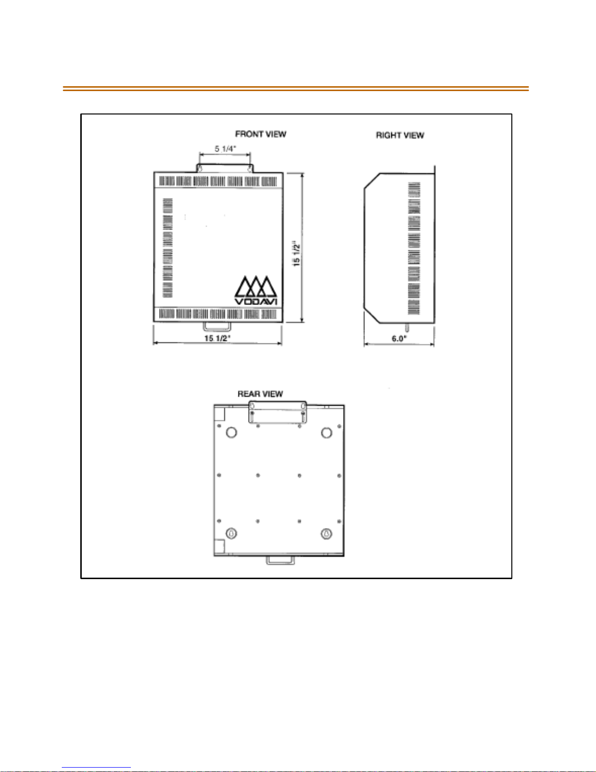
Triad 1Unit Basic KSU Back w/Mounting Plate Extended ............................... 2-9
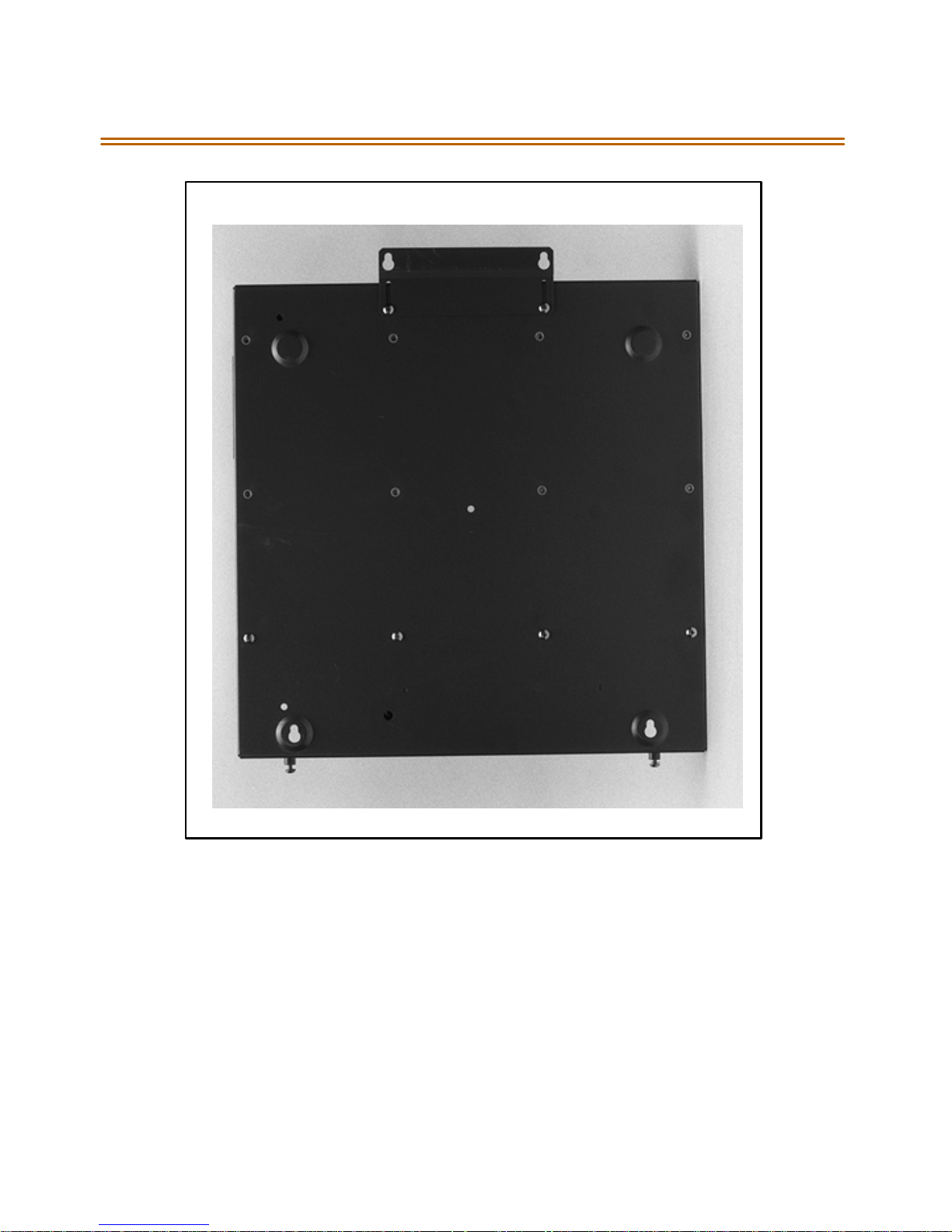
Triad 1 KSU Mounting Holes and Installation Layout ............. .. .. .... .. ................. 2-10
Triad 2 Basic KSU Back w/Mounting Plate Extended ............ .. .. .... .. ................... 2-12
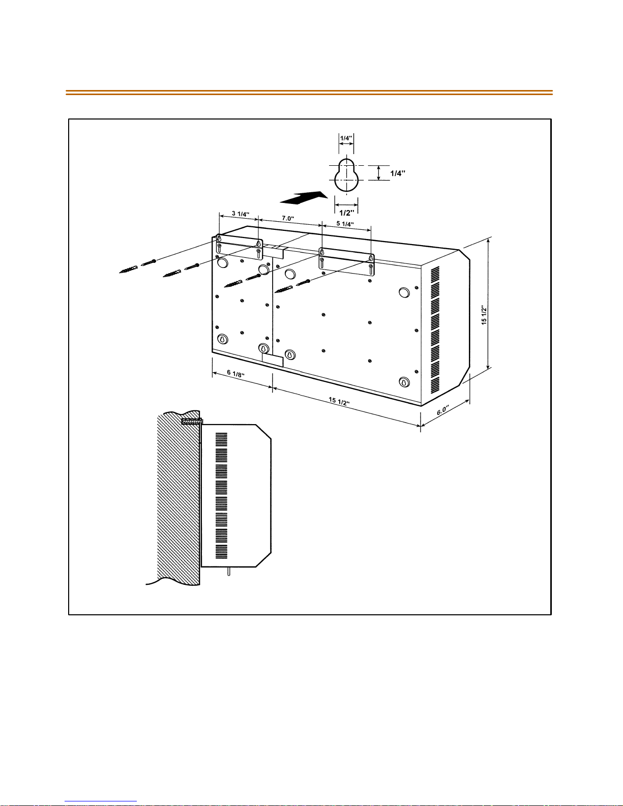
Triad 2 KSU Mounting Holes and Installation Layout ............. .. .. .... .. ................. 2-13
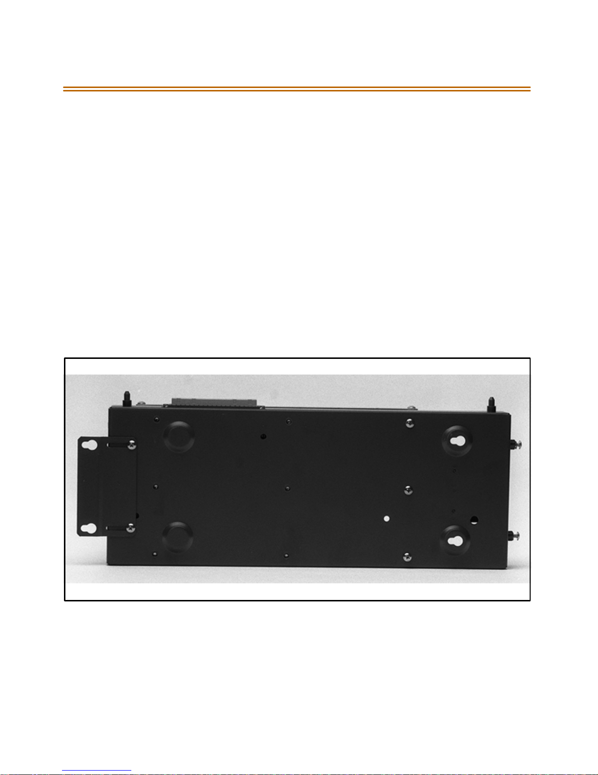
Expansion KSU Back w/Mounting Plate Extended .................... .. .. .... .. .... .. ..... .. .. 2-14
Connection of BKSU and EKSU ............. .. ... .... .. ........................... .. .. .... .. .... .. .... .. ......... 2-15
Ring Generator Installation .............. .. .. .... ... .. .... .. .... .. .... .. .. .... ... .... .. ........................... .. 2-17
Installation of P ower Supply Unit (PSU) ... .. .. .... .. ........................... .. .. .... .. .... .. ..... .. .. 2-19
PCB Installation .................. .. ........................... .. .. .... .. .... .. .... .. ........................... .. .. ..... .. .... 2-23
MPB w/PLLU and MODU Installation .................. .. ........................... .. .. .... .. .... ... .... .. 2-28
Talk Battery ................... .. .. ..... .. ........................... .. .. .... .. .... .. .... .. .. ..... .. .... .. .... .. ................... 2-29
MISU w/SIU Installation ....................... .. .. ..... .. ........................... .. .. .... .. .... .. .... .. .. ..... .. .... 2-32
LCO B w/DTRU Installation ............ .. .. .... .. ..... .. .... .. ........................... .. .. .... .. .... .. .... ... ...... 2-35
DIDB w/ DTRU Installation ............. .. .. .... .. .. ..... .. .... .. ........................... .. .. .... .. ................. 2-38
T-1 Clock Connect Cable Installation (Multiple Cards) ......................... .. ........... 2-44
T-1 Clock Connect Cable Installation (Single Card) .. .. ..... .. .... .. .... .. .. .... .. .... ... .... .. 2-45
T1IB w/DTMF4_A Module Installation ...................... .. .. .... ... .... .. .. .... .. .... .. .... .. ......... 2-47
PRIB (Primary Rate Interface Board) ............................. .. .. ..... .. ........................... .. .. .. 2-49
BRIB (Basis Rate Interface Board) ....... .. .. ..... .. .... .. .... .. ........................... .. .. .... .. ..... .. .... 2-50
Electronic Telephone Interface Board (ETIB) .......... .. .. .... ... .... .. .. .... .. .... .. .... .. ......... 2-59
SLIB w/MSGU and DTRU Module Installation ...................... .. .. .... .. .. .... .. .... .. ..... .. .. 2-63
Digital Telephone Interface Board (DTIB) Installation ............................ .. ... .... .. 2-66
Battery B ack-Up Wiring ........... .. .. .... .. ........................... .. .. .... .. ..... .. .... .. .. .... .. .... .. ..... .. .... 2-67
RS232 9-Pin Connector Wiring . .. .. .... .. .. ..... .. .... .. ........................... .. .. .... .. ................... 2-68
Digital Station Jack Wiring ........... .. .. .... .. ..... .. .... .. .... .. .. .... .. .... ... .... .. ........................... .. 2-69
Electronic Station Wiring .. .... .. .... .. .... .. ........................... .. .. .... ... .... .. .... .. ....................... 2-70
Single Line Telephone Wiring ..... .. .. .... .. ..... .. .... .. ........................... .. .. .... .. .... .. .... ... .. .... 2-71
PFTU Wiring ...... .. .. .... .. .... .. ... .... .. .... .. .... .. ........................... .. .. .... .. ..... .. .... .. .. .... .. .... .. ..... .. ....2-72
Caller ID Cable Connections ............ .. .. .... ... .... .. .... .. ........................... .. .. .... .. .... .. ..... .. .. 2-76
CTI System Configuration . .. .. .... .. ........................... .. .. .... .. .... .. ..... .. ........................... .. .. 2-77
Electronic Key Telephone W all Mounting ............. .. ......................... .. .. .... .. ........... 2-78
Digital K ey Telephone Wall Mounting .................. .. .. .... .. ........................... .. .. ..... .. .. 2-79
Page 11

March 2001 viii
SMDR Printout . .... .. .... .. .... ... .......................... ... .. .... .. .... .. .... .. .. .... ... .... .. .... .. .... .. .. .... .. ..... .. .. 2-80
Basic Cabinet (BKSU) w/Expansion K SU (EK SU1/ EKSU2) ................... .. .. ..... .. .... 3-6
BKSU Mounting Holes ........ .. .. .... .. ........................... .. .. .... .. .... .. ..... .. ........................... .. .. 3-8
Expansion Cabinet ( EKSU2) Installation ................. .. .. .... .. ..... .. .. .... .. .... .. .... .. ..... .. .... 3-10
Ring Generator Installation .............. .. .. .... ... .. .... .. .... .. .... .. .. .... ... .... .. ........................... .. 3-11
KSU Grounding .. .. .... .. .. .... ... .... .. .... .. ........................... .. .. .... .. .... .. ..... .. ........................... .. .. 3-13
AC/DC Power Installation ........... .. .. .... .. .. ..... .. .... .. .... .. ........................... .. .. .... .. .... ... .... .. 3-15
Optional Battery Charging Unit (BCU) .................. .. .. .... .. ..... .. .... .. .. .... .. .... .. .... ... ...... 3-17
DCCU and Optional BCU Installation .......... .. .. .... .. .... .. .... .. ... .... .. .... .. .... .. .... .. .. ..... .. .. 3-18
Typical System Configurations ........... .. ........................... .. .. ..... .. .... .. .... .. .. .... .. ..... .. .... 3-20
Typical System Configurations ........... .. ........................... .. .. ..... .. .... .. .... .. .. .... .. ..... .. .... 3-21
Typical System Configurations ........... .. ........................... .. .. ..... .. .... .. .... .. .. .... .. ..... .. .... 3-22
Typical System Configurations ........... .. ........................... .. .. ..... .. .... .. .... .. .. .... .. ..... .. .... 3-23
Battery B ack-Up Installation ........................... .. .. .... .. .... .. .... .. ........................... .. ... .... .. 3-25
MPB Daughter Boards Installation ............... .. .. .... .. .... .. .... .. ........................... .. ... .... .. 3-34
Talk Battery ................... .. .. ..... .. ........................... .. .. .... .. .... .. .... .. .. ..... .. .... .. .... .. ................... 3-35
MISU & PFTU Installation ........ .. .. .... .. .... .. .. ..... .. .... .. .... .. ........................... .. .. .... .. ..... .. .... 3-39
LCO B w/DTMF-B Installation ...................... .. .. .... .. .... .. ........................... .. .. .... .. ..... .. .... 3-42
GCO B w/DTMF-B Installation .......... .. .. .... ... .......................... ... .. .... .. .... .. .... .. ............... 3-45
DIDB w/ DTMF-B Installation ......................... .. .. .... .. .... .. .. .... .. ..... .. .... .. ......................... 3-48
T-1 Clock Connect Cable Installation (Multiple Cards) ......................... .. ........... 3-54
T-1 Clock Connect Cable Installation (Single Card) .. .. ..... .. .... .. .... .. .. .... .. .... ... .... .. 3-55
T1IB w/DTMF-A Module Installation ........................ .. .. .... .. ........................... .. ... .... .. 3-57
PRIB (Primary Rate Interface Board) ............................. .. .. ..... .. ........................... .. .. .. 3-60
PRIB w/DTMF-A Module Installation .... ... .. .... .. .... .. .. .... .. .... ... .... .. ........................... .. 3-63
BRIB (Basis Rate Interface Board) ....... .. .. ..... .. .... .. .... .. ........................... .. .. .... .. ..... .. .... 3-65
Electronic Telephone Interface Board (ETIB) .......... .. .. .... ... .... .. .. .... .. .... .. .... .. ......... 3-74
SLIB w/DTMF-A and MSG12 Installation .. .. .... .. .... .. .... .. ........................... .. .. ..... .. .... 3-79
DTIB w/ DTIB-E Installation ......... .. .. .... .. .... ... .......................... ... .. .... .. .... .. .... .. .. .... ... .... .. 3-83
Digital Station Jack Wiring ........... .. .. .... .. ..... .. .... .. .... .. .. .... .. .... ... .... .. ........................... .. 3-84
Electronic Station Jack Wiring ... .. .. .... .. ........................... .. .. ..... .. .... .. .... .. ..................... 3-85
Single Line Telephone Wiring ..... .. .. .... .. ..... .. .... .. ........................... .. .. .... .. .... .. .... ... .. .... 3-86
PFTU Wiring ...... .. .. .... .. .... .. ... .... .. .... .. .... .. ........................... .. .. .... .. ..... .. .... .. .. .... .. .... .. ..... .. ....3-87
Caller ID Cable Connections ............ .. .. .... ... .... .. .... .. ........................... .. .. .... .. .... .. ..... .. .. 3-91
Caller ID Cable Connections - Triad 3 SIU .............. .. .. .... .. ..... .. .. .... .. .... .. .... .. ..... .. .. .. 3-91
CTI System Configuration . .. .. .... .. ........................... .. .. .... .. .... .. ..... .. ........................... .. .. 3-92
Page 12

ix March 2001
Electronic Key Telephone W all Mounting ............. .. ......................... .. .. .... .. ........... 3-93
Digital K ey Telephone Wall Mounting .................. .. .. .... .. ........................... .. .. ..... .. .. 3-94
SMDR Printout . .... .. .... .. .... ... .... .. .. .... .. .... .. .... .. ..... .. .. .... .. .... .. .... .. ..... .. .. .... .. .... .. .... .. .... ... .. .... 3-95
Maintenance Help Menu .. .. .. .... .. ........................... .. .. .... .. .... .. ..... .. .. .... .. .... .. .... .. ..... .. .. .. 5-17
Remote System Configuration . .. .... .. .... .. ........................... .. ... .... .. ........................... .. 5-18
Station Configuration .......... .. .. .... .. .... .. .... .. ..... .. .. .... .. .... .. .... .. ........................... .. .. ..... .. .. 5-19
CO Line Configuration ........... .. .. .... .. .... .. .... ... .. .... .. .... .. .... .. .... .. ... .... .. .... .. .... .. ................. 5-20
Help Menu ................. .. .. .... ... .... .. .. .... .. .... .. .... .. ..... .. .. .... .. .... .. .... .. ........................... .. .. ..... .. .. 5-23
Trace Mode Status ............................... .. .. .... ... .... .. ........................... .. .. .... .. .... .. .... .. ......... 5-24
Enable Event Trace ...................... .. .. .... .. .... .. ........................... .. ... .... .. .... .. .... .. ................. 5-26
Event Trace ....... .. ........................... .. .. .... .. .... .. ..... .. .. .... .. .... .. .... .. ........................... .. .. ..... .. .. 5-27
Page 13

x March 2001
Page 14

March 2001 xi
Tables
MPB Switc h Positions ......................... .. .. .... ... .......................... ... .. .... .. .... .. .... .. .. .... ... .... .. 2-24
MISU Wiring ................ .. .. ..... .. .... .. .. .... .. .... .. .... ... .......................... ... .. .... .. .... .. .... .. ...............2-30
LCO B Wiring ............. .. .. .... ... .......................... ... .. .... .. .... .. .... .. .. .... ... .... .. .... .. .... .. .. .... .. ..... .. .. 2-34
DIDB Wiring ............................. .. .. .... .. .... .. .... .. ... .... .. .... .. .... .. ........................... .. .. .... .. ..... .. ..2-37
T-1 Board LEDS ............................. .. .. .... .. .... .. ..... .. ........................... .. .. .... .. .... .. .... .. .. ..... .. .. 2-39
T-1 Ordering Information ..... .. .. .... .. .... .. .... ... .......................... ... .. .... .. .... .. .... .. .. .... ... .... .. 2-40
T-1 Switch P ositions . .. .... ... .... .. ........................... .. .. .... .. .... .. .... .. ... .... .. .... .. .... .. ................. 2-40
Call Routing Criteria . .. .. ..... .. .... .. .... .. ........................... .. .. .... .. .... ... .... .. .. .... .. .... .. .... .. ..... .. .. 2-42
Call Routing Display Format .. .... .. .... .. .. .... ... .... .. .... .. .. .... .. .... .. ........................... .. ... .... .. 2-42
T-1 Ordering Specifications ..................... ... .. .... .. .... .. ........................... .. .. .... .. .... ... .... .. 2-43
ETIB Wiring .............. .. ........................... .. .. .... .. ..... .. .... .. .. .... .. .... .. ..... .. ........................... .. .... 2-58
SLIB Wiring ............ .. .. .... .. ..... .. .... .. .. .... .. .... .. .... ... .......................... ... .. .... .. .... .. .... .. ............... 2-60
DTIB Wiring ................. .. .. ..... .. ........................... .. .. .... .. .... .. .... .. ........................... .. .. ..... .. .... 2-65
System Back-Up Duration .... .. .. .... .. .... .. .. ..... .. .... .. .... .. ........................... .. .. .... .. .... ... .... .. 2-68
Power Consumption per Card ............................. .. .. .... .. .... .. ........................... .. ... .... .. 3-19
System Back-Up Duration .... .. .. .... .. .... .. .. ..... .. .... .. .... .. ........................... .. .. .... .. .... ... .... .. 3-24
MPB Dip Switch Functions ............... .. .. .... ... .......................... ... .. .... .. .... .. .... .. .. .... ... .... .. 3-30
I/O Port RS23 2 Co nnections ....................... .. .. .... .. .... .. .. .... .. ..... .. .... .. ........................... 3-30
MISU Wiring ................ .. .. ..... .. .... .. .. .... .. .... .. .... ... .......................... ... .. .... .. .... .. .... .. ...............3-36
Power Failure Transfer Unit (PFTU) W iring ........ .. .. .... .. .... ... .. .... .. .... .. .... .. ............... 3-38
LCO B Wiring ............. .. .. .... ... .......................... ... .. .... .. .... .. .... .. .. .... ... .... .. .... .. .... .. .. .... .. ..... .. .. 3-41
GCO B Wiring ........................ .. .. .... .. .... .. .... .. ........................... .. .. ..... .. .... .. .... .. ..................... 3-44
DIDB Wiring ............................. .. .. .... .. .... .. .... .. ... .... .. .... .. .... .. ........................... .. .. .... .. ..... .. ..3-47
T-1 Board LEDs .......................... .. .. .... .. .... .. .... ... .......................... ... .. .... .. .... .. .... .. ............... 3-49
T-1 Ordering Information ..... .. .. .... .. .... .. .... ... .......................... ... .. .... .. .... .. .... .. .. .... ... .... .. 3-50
T-1 Switch P ositions . .. .... ... .... .. ........................... .. .. .... .. .... .. .... .. ... .... .. .... .. .... .. ................. 3-50
Call Routing Criteria . .. .. ..... .. .... .. .... .. ........................... .. .. .... .. .... ... .... .. .. .... .. .... .. .... .. ..... .. .. 3-52
Call Routing Display Format .. .... .. .... .. .. .... ... .... .. .... .. .. .... .. .... .. ........................... .. ... .... .. 3-52
PRIB Board LEDs ................... .. .. .... .. .... .. .... .. ........................... .. .. ..... .. .... .. .... .. .. .... .. ..... .. .... 3-58
PRI Ordering Inf ormation ..... .. .. .... .. ........................... .. .. .... .. ..... .. .... .. ........................... 3-59
Call Routing Criteria . .. .. ..... .. .... .. .... .. ........................... .. .. .... .. .... ... .... .. .. .... .. .... .. .... .. ..... .. .. 3-61
Call Routing Display Format .. .... .. .... .. .. .... ... .... .. .... .. .. .... .. .... .. ........................... .. ... .... .. 3-62
ETIB Wiring .............. .. ........................... .. .. .... .. ..... .. .... .. .. .... .. .... .. ..... .. ........................... .. .... 3-73
SLIB Wiring ............ .. .. .... .. ..... .. .... .. .. .... .. .... .. .... ... .......................... ... .. .... .. .... .. .... .. ............... 3-77
Page 15

xii March 200 1
DTIB Wiring ................. .. .. ..... .. ........................... .. .. .... .. .... .. .... .. ........................... .. .. ..... .. .... 3-82
Power Supply Tests .. .. .... ... .. .... .. .... .. .... .. .... .. ... .... .. .... .. .... .. ........................... .. .. .... .. ..... .. .. 4-4
Triad 3 DCCU Test Points .................... .. .. ..... .. .... .. .... .. .. .... .. .... ... .... .. .... .. .. .... .. .... .. ..... .. .. 4-4
Flash R ates .............. .. .. .... .. ..... .. .. .... .. .... .. .... .. ........................... .. .. ..... .. .... .. .... .. ................... 5-5
Key Telephones/Terminals . .... .. .... .. .. .... .. ..... .. .... .. ........................... .. .. .... .. .... .. .... ... ...... 5-7
Single Line Telephones ... .. .. .... .. .... .. .... .. .. ..... .. .... .. .... .. ........................... .. .. .... .. .... ... .... .. 5-8
DSS/DLS Console .. .. .... .. ..... .. .... .. ........................... .. .. .... .. .... .. .... ... .......................... ... .. .... 5-8
CO Line Loop Start Interface B oard ( LCOB) . .. .... .. .... .. .... .. ..... .. .. .... .. .... .. .... .. ..... .. .... 5-9
CO Line Ground Start Interface Board (GCOB) (Triad 3 only) . .... .. .... .. .... ... .... .. 5-9
Direct Inward Dial Interface B oard ( DIDB) . .... .. .... .. .... .. .... ... .... .. .... .. .... .. ................. 5-10
PRIB Switches ...................... .. .. .... .. .. .... .. .... .. ..... .. .... .. .. .... .. .... .. .... ... .... .. .. .... .. .... .. .... .. ..... .. .. 5-10
Master Processor Board (MPB) ............................... .. .. .... .. .... ... .. .... .. .... .. .... .. ............... 5-11
Memory Expansion Module Unit (MEMU) (Triad 3 only) . .... .. .... .. .... .. .... .. ... .... .. 5-11
Modem Unit (MODU) ............... .. .. .... .. .... .. ..... .. ........................... .. .. .... .. .... .. .... .. ............. 5-12
Program Module Unit ( PMU) ................... ... .. .... .. .... .. .... .. .. .... ... .... .. .... .. ....................... 5-12
Power Supply Unit (PSU) ................. .. .. .... .. ..... .. .... .. .. .... .. .... .. ..... .. ........................... .. .. .. 5-12
Miscellaneous Interface Bo ard (MISU) ................ .. .. .... .. .... ... .. .... .. .... .. .... .. .... .. ... .... .. 5-13
DTMF Receiver Unit (DTRU, DTMF-A, DTMF-B) ............................. .. .. .... .. ............. 5-13
Ring Generator Unit (RGU) ......... .. .. .... .. .... ... .. .... .. .... .. ........................... .. .. .... .. ............. 5-14
Power Failure Transfer Unit (PFTU) .................... .. .. .... .. .... .. ... .... .. .... .. .... .. .... .. .. ..... .. .. 5-14
Digital K ey Terminal Interface Board (DTIB) .. .. .. .... .. .... .. ..... .. ........................... .. .. .. 5-15
Single Line Interface Board (SLIB) w/MSGU ........................... .. .. .... .. .... .. .... .. ..... .. .. 5-15
Event Trace B uffer Commands ...................... .. .. .... .. .... .. .... .. ... .... .. .... .. .... .. ................. 5-21
Page 16

1
Introduction
This manual provides the information necessary to install and
maintain the STARPLUS Triad 1/2/3 Systems. The described features
are based on the current software release. If any of these features do
not work on your system, call your sales representative regarding
upgrading your system.
Page 17

Page 18

Regulatory Information (U.S.A.) 1-3
Regulatory Information (U.S.A.)
The Federal Communications Commission (FCC) has established rules
which allow the direct connection of the T riad 1 /2 /3 Systems to the
telephone network. Certain actions must be undertaken or understood
before the connection of customer provided equipment is completed.
Telephone Company Notification
Before connecting the Tri ad 1 /2 /3 Systems to the telephone network, the
local serving telephone company mus t be given advance notice of
intention to use customer provided equipment and p rovided with the
following information:
Telephone Numbers
The telephone numbers to be connected to the system.
Triad 1/2 Systems Information
The Ringer Equivalence Number also located on the KSU: 1.3B
The USOC jack required for direct interconnection with the telephone
network:RJ11C
Triad 3 System Information
The Ringer Equivalence Number also located on the KSU: 1.3B
The USOC jack required for direct interconnection with the telephone
network:RJ21X
FCC Regis trat ion Numbe rs
For systems conf igured as a key system: (button appearances)
DLPKOR-24039-KF-E
For systems configured as a Hybrid system: (dial access codes)
DLPKOR-24026-MF-E
Page 19

1-4 Regulatory Informat ion (U.S.A.)
Incidence of Harm
If thetelephone company determines that the customer provided
equipment is faulty and possibly causing harm or interruption to the
telephone network, it should be disconnected until repairs can be made.
If this is not done, the telephone company may temporarily disconnect
service.
Changes in Service
The local telephonecompany may make changes in its communications
facilities or procedures. If thesechanges should affect the use of theTriad
1/2/3 S yst ems or com pat ibil ity with the networ k, t he te lephone compan y
must give written notice to the user to allow uninterrupted service.
Maintenance Limitations
Maintenance on the Triad 1/2/3System s is to be perfor med only by the
manufacturer o r its authorized agent. The user may not makeany
changes and/or repairs except as specifically noted in this manual. If
unauthorized alterations or repairs a re made, any remainin g warranty
and the software license for the systemwillbe voided.
Hearing Aid Compatibility
Al l Triad 1/2/3 Digital Telephonesare Hearing Aid Compatible, as defined
inSection68.316ofPart68FCCRulesandRegulations.
UL/CSA Safety Compliance
The Tr iad 1 /2 /3 Sys tems have met all safety requirements and were found
be in com pliance with the Underwriters Lab oratories (U L) 1459. Th eTriad
1/2/3 Systemsare authorized to bear the NRTL/C marking.
Page 20

Toll Fraud Disclaimer 1-5
Notice of Complianc e
The Triad 1/2/3 Systems com ply with rules regarding radiation an d radio
frequency emissions by C lass A computing de vices. In accordance with
FCC Standard 15 (Subpart J), the following informa tion must be supplied
to the end user:
“Thi s e quip men t gen era tes and u ses R F e ne rgy an d i f not i ns tall ed a nd
used i n acco rdance wit h the Instruc tion Manual, ma y cause i nterference
to Radio Co mmunications. It has been tested and found to comply with
the limits fora Cl ass A computi ng device , pursuan ttoSubpart J of Pa rt15
oftheFCCRules,whichare designedtoprovidereasonableprotection
agai ns t su ch int erf e ren ce, wh en op er a ted in a c omm ercial e nv iro nm en t.
Opera tion o f th is equ ipment in a residential are a is lik ely to ca use
interference, in whic h case the use r, at hi sown expense, will be required
to take whatever measures may be required to correct the interferenc e.”
To l l F r a u d D i s c l a i m e r
“While this device is designed to be reasonably secure against intrusions
fromfraudulent callers, itis by no meansinvulnerable to fraud. Therefore,
no express or implied warranty is made ag ain st such fraud includ ing
interconnection to the long distance network.”
“While this device is d esigned to be reasonably secure against invasion of
privacy, it is by no means invulnerable to such invasions. Therefore, no
express or imp lied warranty is made against un lawf ul or unauthorized
utilization which resultsinthe invasion ofone’s right of privacy.”
Page 21

1-6 Toll Fraud Disclaimer
Page 22

Triad 1/2 System
2
This chapter contains the basic system installation and wiring
instructions for the Triad 1/2 Systems, as well as how to install the
optional cards and units.
Installation
Page 23

Page 24

Introduction 2-3
Introduction
As with any sophisticated communications device, installationof the
Triad 1/2 Syst ems, r equir es t he care a nd forethough t of a competent
technician. To assure easy servicingand reliable operation, several factors
must be considered when planning the system installation. The
installation consistsof thesemajor steps:
Site Preparation
KSU and Power Supply (PS) Installation
PCB Installation
Sys tem Wiring
Keyset an d Ter minal I nstallation
Basic Installation Check-Out
SystemProgramming and Verification
Ins ta llin g t he STARPLUS Triad 1/2 Sy stem is quick and e fficient if these
ins tallat ion ins tructions are followed.
Page 25

2-4 Site Preparation
Site Preparation
General Site C onsiderations
The first step is tolocate anacceptable site for the commonequipment
(KSUs, b oards, etc.). When locating a mounting site for the KSUs, the
following points must be considered.
The KSUs are designed for wall mounting and should not be
mounted direc tly t o a masonry or plas terboard wall. It is
recommended that a 1/2 inch plywood back board be firmly
mounted to the wall, and the KSU and MDF, if other than the MDF, be
mounted to the back board.
The location must have a ccess to a dedicated 110 Volt AC (±10%), 60
Hz , si ngl e-p hase cir cuit with a cir cuit breaker or f use rat ed a t 15 amps .
A 3-wire (parallel blade grounded outlet should be within
approximately 6 feet of the lower left rear of the BKSU mounting.
The location must have a ccess to a good earth ground, such as a
metallic cold water pipe with no non-metallic joints. The ground
sourceshould be located asclose aspossibleto the system.
The system s hould be lo cated in an area which is well ven tila ted with
a r ecommended temperature r ange of 68°-78° Fandarelative
humidity range of 5-60% (non condensing).
Thesystemshouldbelocatedwithin25feetofthetelephone
company’s te rmina tion p oint. Al so, the location s houl d be wi th in the
prescribed station loop lengths for al l keys ets and terminals. If
existing cablingisto be used, thelocation of existing cabling and
conduits should be considered.
Protection from flooding,flammable materials, excessive dustand
vibration.
The site should be away fromradiotransmitting equipment, arcweldingdevices, copying machines andother electrical equipment
that are ca pable of generating electrical interf erences. Operation of
this equipment in a residential area is likely to cause interferencein
which case the user, at their own expense,are requiredto take
whatever measur es may be required t o correct the interfe rence.
Page 26

Site Preparation 2-5
Back-Board Installation
A wooden back-board is recommended for all installations and must be
installed when the location has masonry or plasterboard walls. A 1/2 inch
plywood material is sufficient for most installations. The back-board
should be mountedat aconvenient height, about 3 feet above the floor
and bol ted i n a numbe r of p lace s to dis tribute t he wei ght of th e s ystem .
Spaceshouldbeavailableonthebottomsideoftheback-boardforthe
MDF cabling and for optional equipment such as a music source and
PFTU , etc. It is recommended the location of each major item be roughly
sketched on the back-b oard as an installation layout.
Verify On-Site Equipment
Once the equipment installation site has been identified and a dedicated
AC outlet,earth ground,andlighting and ventilation are available, verify
that all equipment requiredis on-siteandhas not been damagedduring
shipment. Unpack the KSUs to assure there is no shipping damage. Note
that a m ounting te mplate is packed with each KSU and this template is
required later in the installation. Check that the type and quantity of
boardsreceiveiscorrect andoptional equipment anda Power Line Surge
Protector are on-site. Note thatthe individual boards should NOT be
unpack ed at th is time.
If any equ ipm ent is damaged o rm issing, notify the approp riate
personnel to correct the situation.
Page 27
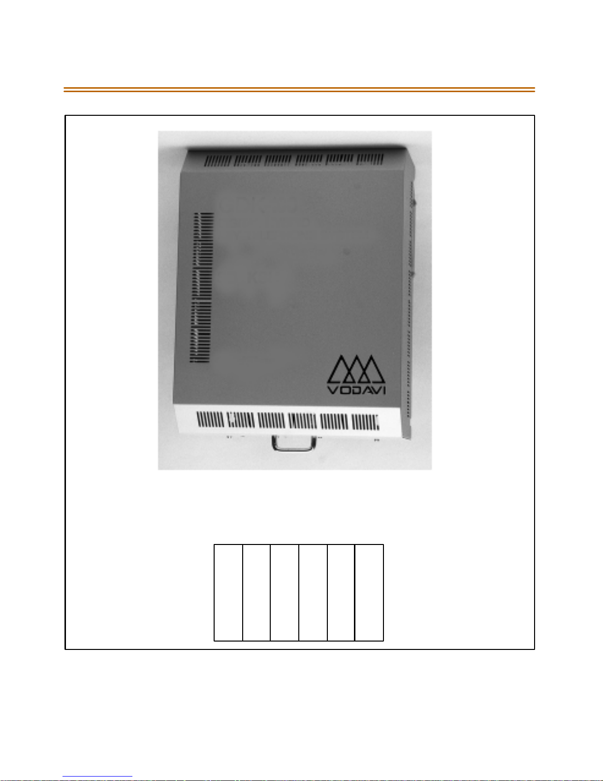
2-6 Site Preparation
Figure 2-1:Triad 1 Default Card Layout
DEFAULT CAR D L AYO UT
SLOTS
01267
D
D
L
C
O
B
N
O
N
E
D
T
I
B
T
T
I
I
B
B
MPB
M
P
B
Page 28
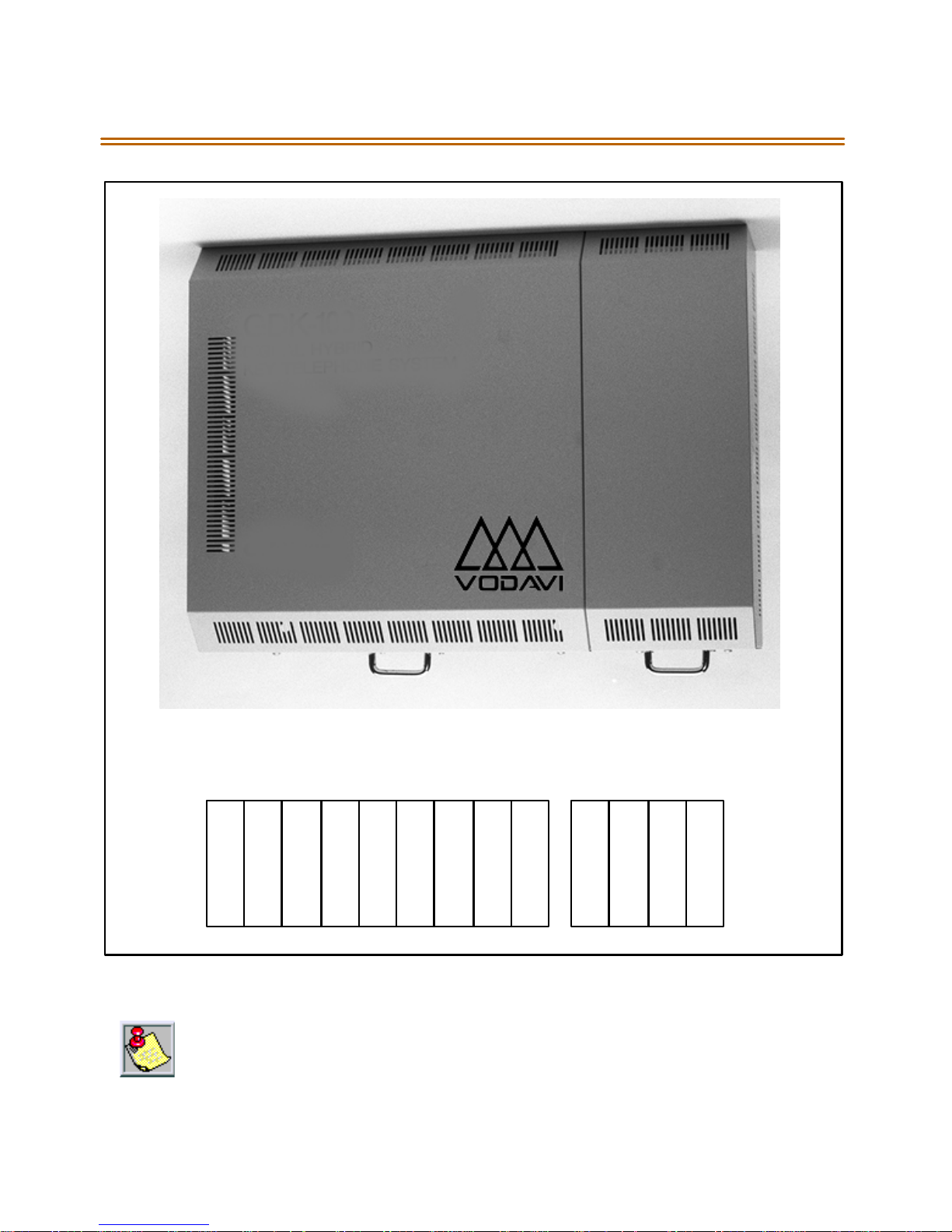
Site Preparation 2-7
DEFAULT CARD LAYOUT
SLOTS
D
T
I
B
23456
D
D
D
L
T
T
T
C
I
I
I
O
B
B
B
B
L
C
O
B
L
C
O
B
MPB01
7101189
N
O
N
E
M
P
B
N
O
N
E
N
O
N
E
N
O
N
E
N
O
N
E
Fi gu re 2- 2: Triad 2 Key Service Unit (BKSU/EKSU)
In certain con figurations, it is p ossible to not h ave all ca rd slots utilized due to power
suppl ycapacities.Use the C onfigurator Progr amto calcu late the correctconfigura tion.
Page 29

2-8 KSU & Power Supply ( PSU) Inst allation
KSU & Power Supply (PSU) Installation
The Triad 1 System consists of a Basic KSU (BKSU) cabinet. The basic
exterior of the Triad 1 System is show n in Figure 2-2.
Mounting the Tr i ad 1 Basic KSU
The Basic KSU is a metal frame cabinet d esigned for wall mounting.
Employing the KSU mounting template provided with the BKSU, mark
the location of the two screws to mount the BKSU. Again, the KSU must
NOT be mounted on a masonry or dry-wall surface, in this case a wooden
back-board is required.Refer to the next diagramfor the distance
between mounting holes.
The BSKU is mounte d with four # 10 or l arger, 1 ½ inch or longer screws.
1. Drill pilot holes in the two locations marked, insert the screws and
tight en le avi ng a bout ½ inch expos ed.
2. Mount the Basic KSU on the screws and tighten the screws securely.
3. Remove the front cover by turning the two cover screws counter
clockwise.
4. Tilt a nd l ift the cover to r emove.
5. Insert the screws to the mounting holes of the BKSU and tighten the
screwsasshown.
Page 30
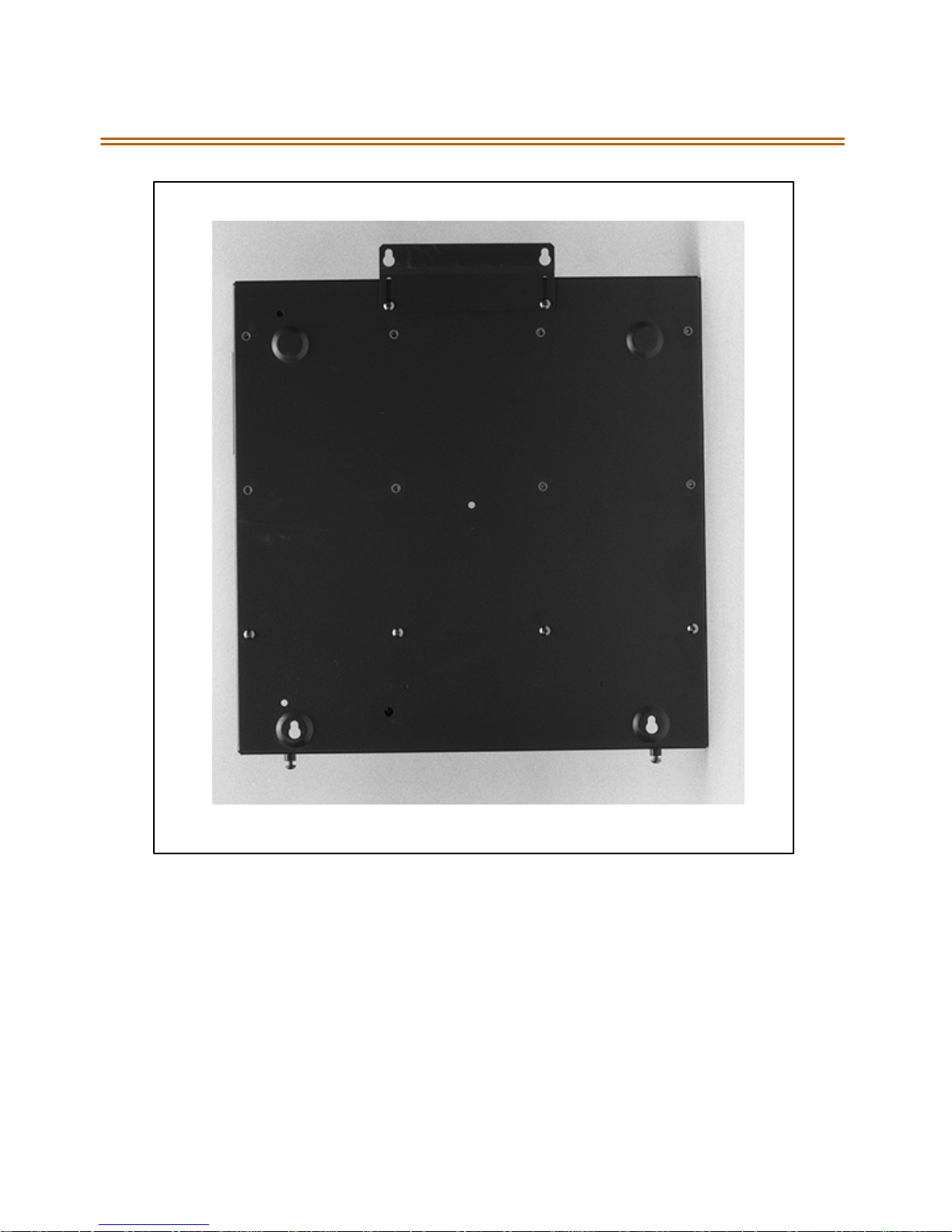
KSU & Power Supply (PSU) Installation 2-9
Figure 2-3: Triad 1 Unit Basic KSU Back w/Mounting Plate Extende d
Page 31
2-10 KSU & Power Supply (PSU) Installation
Figure 2-4: Triad1 KSU Mounting Holes and Installation Layout
Page 32

KSU and Power Supply (PS) Installation 2-11
KSU and Power Supply (PS) Installation
The Triad 2 System consists of a Basic KSU (BKSU) and Expansion KSU
(EKSU). The basic exterior of the Triad 2 Sy stem is shown in Figure 2-2.
Mounting the Tr i ad 2 Basic KSU
The Basic KSU is a metal frame cabinet d esigned for wall mounting.
Employing the KSU mounting template provided with the BKSU, mark
the location of the two screws to mount the BKSU. Again, the KSU must
NOT be mounted on a masonry or dry-wall surface, in this case a wooden
back-board is required.Refer to Fi g ur e 2 - 2 forthedistance between
mounting holes.
The BSKU is mounte d with four # 10 or l arger, 1 ½ inch or longer screws.
1. Drill pilot holes in the two locations marked, insert the screws and
tight en le avi ng a bout ½ inch expos ed.
2. Mount the Basic KSU on the screws and tighten the screws securely.
3. Remove the front cover by turning the two cover screws counter
clockwise.
4. Tilt a nd l ift the cover to r emove.
5. Insert the screws to the mounting holes of the BKSU and tighten the
screwssecurely.
Page 33
2-12 KSU and Power Supply (PS) Installation
Figure2-5:Triad 2 Basic KSU Back w/Mounting Plate Extended
Page 34
KSU and Power Supply (PS) Installation 2-13
Figure 2-6: Triad2 KSU Mounting Holes and Installation Layout
Page 35
2-14 KSU and Power Supply (PS) Installation
Mounting the Expansion KSU (EKSU)
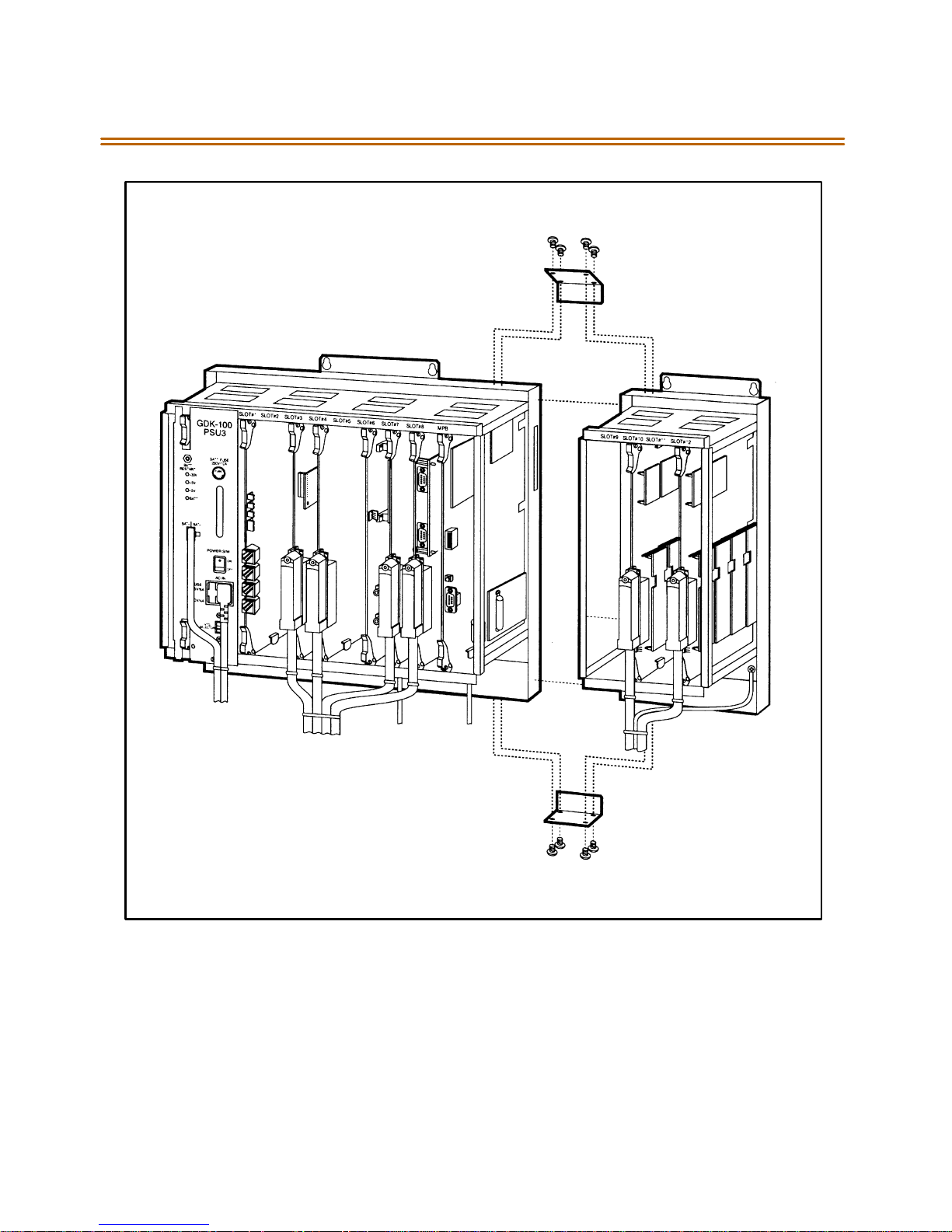
The Expansion KSU is a metal housing designed for wall mount
installation. If required, anEKSU is mountedon the rightside of the BKSU.
1. Before mounting theExpansion KSU, remove the KSU
Interconnection Cover on the rightside of the Basic KSU.
2. Mount the Expansion KSU on the screws and tighten the screws
securely.
3. Mount the 2 side brackets b etween the Basic an d Ex pansion KSUs.
4. Remove the front cover by turning the two front cover screws
counter clockwise.
5. Tilt a nd l ift the cover to r emove.
6. Interconnection is achieved via a amphenol type connector. No cable
is used to connect the BKSU and the EKSU together. Refer to
Figure 2-8.
Figure 2-7: Expansion KSU Backw/MountingPlate Extended
Page 36
KSU and Power Supply (PS) Installation 2-15
Figure 2-8: Connection ofBKSU and EKSU
Page 37

2-16 Ring Gen erator Ins tallat ion (RGU)
Ring Generator Installation (RGU)
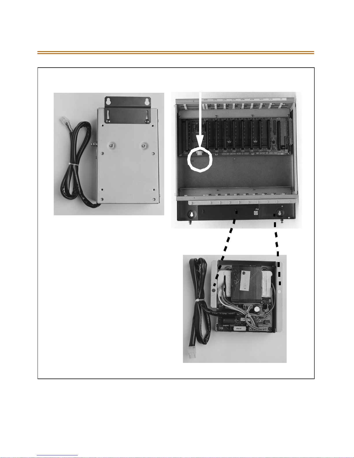
The Ring Generator Unit is needed inthe BKSU where a SLIB is to be
installed, to provide ring voltage and Message Wait source power.
Accordingto the installation site, two types ofRGUsare available:
External and Internal.
The external RGUis mountedoutside the KSU to the wall withthe
two screws provided and is connected to the system backplane via
the CN12 (PCB lettering) connector.
The internal RGU is mounted inside the BKSU to the bottom side
panel with the two screws provided and is connected to the system
back plane via the CN12 (PCB lettering) connector.
Page 38
Ring Generator Installation (RGU) 2-17
EXTERNAL RGU
CN12 CONNECTOR
INTERNAL
RGU
InternalRGU supports uptotwo (2)SLIB
Boards.
Beyond two boards requ ires the Extern al
RGU in placeof the Internal RGU.
Figure 2-9: Ring Generator Installation
Page 39

2-18 Power Supply Unit Installation
Power Supp ly Un it Inst allat ion
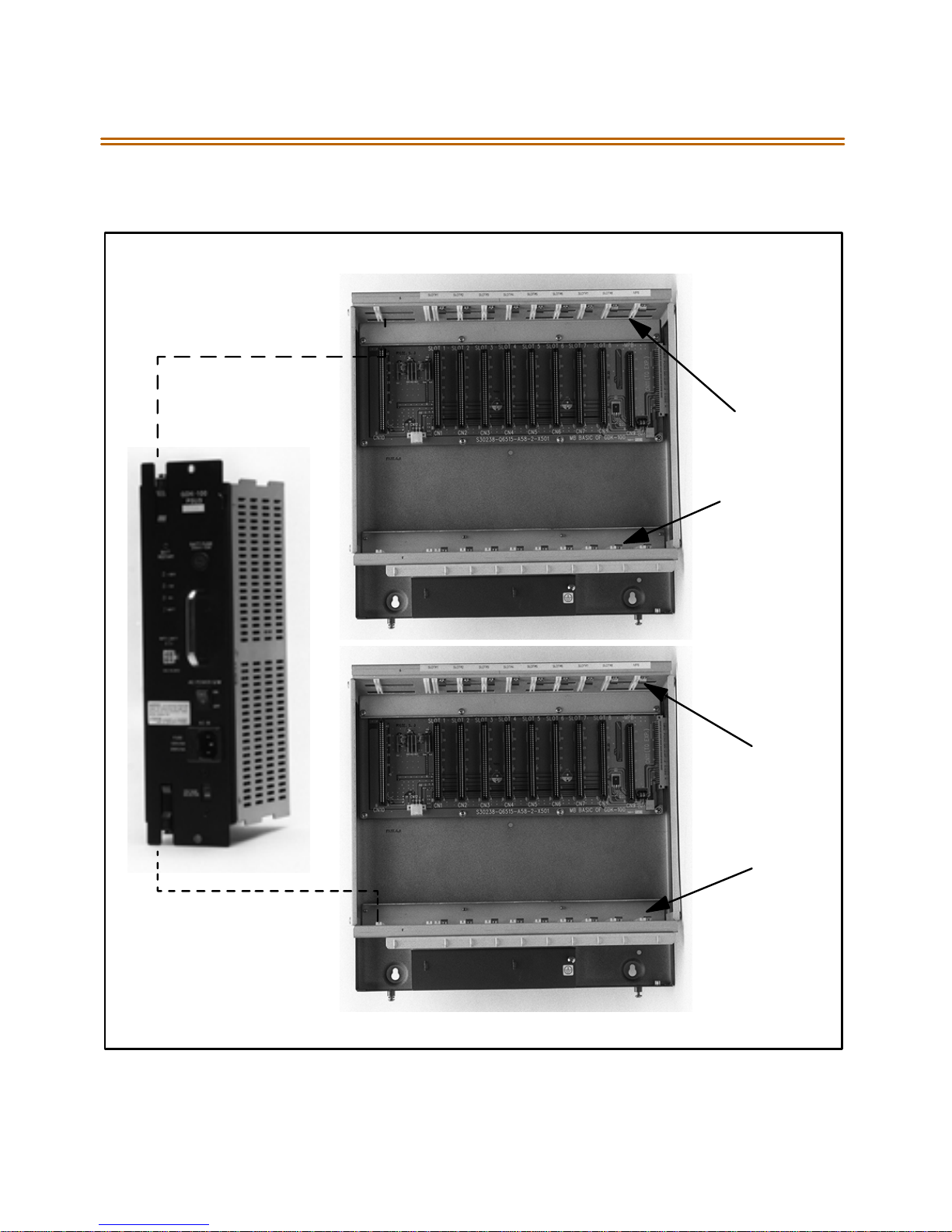
The Power Supply Unit provides power for the system boards and
telephones, converting AC voltage input to appropriate DC voltages.
Before Installation:
As sur e tha t t he A C p lug co nnected to th e BKSU i s N OT plu gged into
the AC outl et.
Place the PSU in the left most slot in the BKSU, aligning the card
gui des with the PSU P CB a nd PSU frame fl ange s.
The PSU can operate from either 115 or220voltsAC based on the setting
of the VTG Selector Switch on the lower front of the PSU.
If local AC is 110 volts, move the switch to the upper position to
display 115V.
If local AC is 220 volts, move the switch to the lower position to
display 220V.
Al though, the Triad 2 System PSUs are equipped with power-line
transient protection, an external Power Line S urge Protector should be
installed at the AC outlet to give additional protection,especiallyduring
violent thunderstorm activity. Refer to Lightning Protec tio n.
Page 40
Power Supply Unit Installation 2-19
Triad 1
CARD
GUIDES
Figure 2-10: Installation of Power SupplyUnit(PSU)
Triad 2
CARD
GUIDES
Page 41

2-20 KSU Grounding
KSU Grounding
To ensure proper sy stem op eration and f or safety purposes, a good earth
groundis required. A metallic COLD waterpipe usually provides areliable
ground. Carefully check that the pipe does not contain insulated joints
tha t could is ola te the grou nd. In t he absen ce of th e C OL D water pipe, a
groundrod or othersource may be used.
A #14 in sul ated AWG or la rge r copper wir e shoul d b e used betwe en the
ground source and the KSU. The wire should be kept as short as possible,
it i s re commen ded that the wire b e n o lo nger t han 25 feet.
Grounding Instructions
1. Remove about 1½ inches of insulation from both ends. Attach one
end of the wire to the Ground Lugon thelower left side of the Basic
KSU by inserting the wire under the lug screw and tighten the screw
securely.
2. Attach the oth er end of the wire as ap prop riate to the ground s ource.
3. Take a DC resistance reading and an AC Volt reading between the
chassis ground point (cold water p ipe) and AC ground (third wire AC
ground). Thelimit is 5V AC and 5 OhmsDC resistance. If ahigher
reading is obtained, choose a different chassis ground point and
repeat thisstep until asuitable ground point isfound.
G rounding t o an electrica l cond uit i s NOT considered a goo d
ground!
Page 42

Power Line Surge Protection 2-21
Power Line Surg e Prot ection
The AC outlet should be equipped with an additional power line
transient surge protection device. Systems using such devices are more
resistant to damage from power line s urges tha n unprotected systems.
Power line surges often occur during switching operationsandespecially
during violent thunderstorm activity.
Installation of a surge protector meeting the specifications described in
the follow paragraph prevents or minimizes the d amage resulting from
power line surges.
The isolation transformer/surge protector shall be a 15 amp self
contained unit that plugs into a standard grounded 117 VAC wall outlet.
Thewalloutletmustbedesignedtoaccepta3-prongplug(2parallel
blades and ground pin). The protector should be fast operating and
capable of protecting transients greater than 200 volts.
It is re commended th at the AC outle t be equipped with an isolation
transformer/surge protection device that utilized MOV p rotection.
Lightning Protection
The system provides secondary protection per UL 1459 Specifications.
Primary protection circuitry is the installers responsibility and shouldbe
installed per the National Electric Code (NEC).
KSU AC Power Plug
Before plugging the KSU power cord into the AC source, verify that the
Power switch on the AC/DC front panel is off.
Plug the KSU power cord into the AC outlet and turn the AC/DC Power
switch on. The red/green LED on the PSUs should illuminate.
Page 43

2-22 PCB Installation
PCB Installation
PCB Handling & General Installation
All Boards SHOULD NOT be Installed or Removed with Power Applied.
Power must be turned off prior to insertion or removal of the PCBs.
The syst em PCBs con tai n d igi tal cir cuitry whi ch, while extreme ly re liable ,
can be damaged by exposure to excessive static electricity. When
handlingPCBs,a grounded wrist strap should be usedto protect the
boards from static discharges. Also, use common sense when handling
PCBs. For example, do not place a PCB in locations where heavy objects
might fall on the PCB and damage components.
OnlyDTIBtype stations can beused for Databaseprogramming.
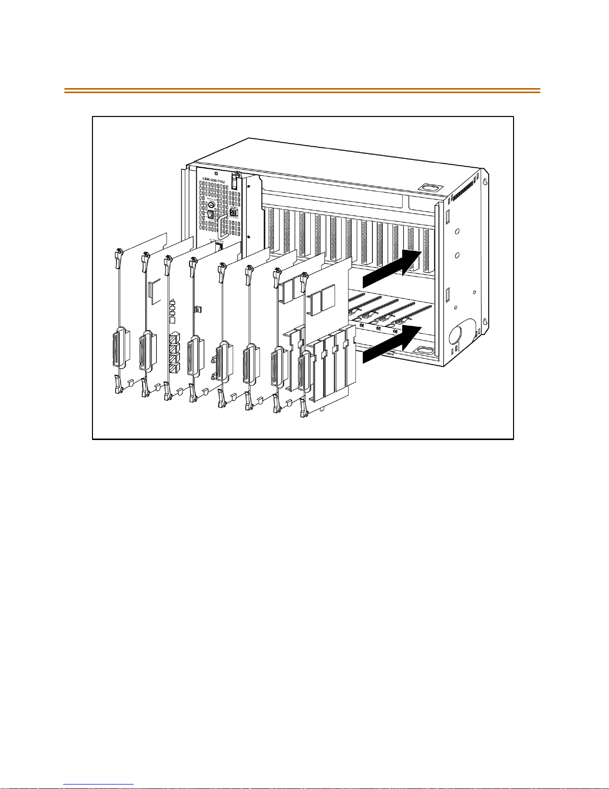
Inserting a PCB
1. Hold the PCB by the injector tabs and, with the components facing
right,align the top and bottom edge of the PCBin the card guides.
2. SlidethecardintothesystemandusetheinjectorstoseatthePCB
firmlyinto the backplane connector.
Removing a PCB
Reverse the Inserting a PCBprocedure. Installation method of PCB is
shown in Figure 2- 11.
There is a ground tab located on the top and bottom of each PCB toward
the front endof the card.Thereisalso a groundtab located to therightof
each card guide in each cabinet. Make sure when the PCBs are inserted
into the card guide and secured in their respective card slots, that the
groundtaboneachcardmateswiththegroundtabon each cardguide.
This ensure a goodground potential to reduce RFI and EMI interference
poss ibilities.
Page 44
PCB Installation 2-23
Figure 2-11: PCB Installation
Page 45
2-24 Main Processor Board (MPB ) Installation
Main Processor Board (MPB) Installation
The MPB is installed in the right most PCB card slot (slot MPB) ofthe
BKSU. The MPB contains a lithium dry-cell to maintain memory and
real-time clock functions. The battery is soldered to the MPB and
connected to the circuitry by anOn-Off DIP switch. Make sure the DIP
switch is O N
TheMPBmaybeequippedwiththreedaughterboards:AMEMUfor
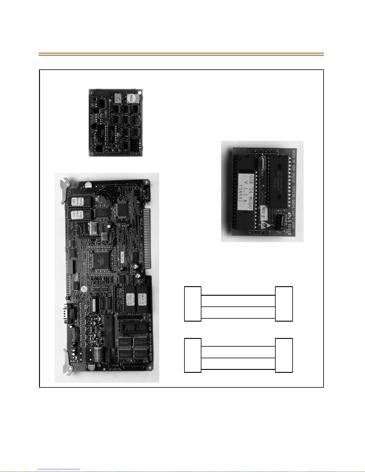
memory expansion, a MODU for modem access to the system, and a
PLLU for T-1 synchronization. Refer to Fi gure 2- 12. The MEMU is not
utilized at this time.
The MPB also has an eight position dip switch. The following is the
function of each switch position:
before the MPB installation.
Table 2 -1: MPB Switch Posit ions
Switch 1 Not Used
Switch 2 Not Used
Switch 3 Not Used
Switch 4 Handshaking ON: XOFF/XON
OFF: CTS/RTS
Switch 5 Not Used
Switch 6 Tests ON: Execute H/W tests at start up
OFF: Skip H/W tests at start-up
Switch 7 Status ON: Displaystart up status at start-up.
OFF: No start-up display status
Swi tch 8 DB Flu sh ON : Flush the database
OFF: Retainthedatabase
Use e xtra care when removin g RS232 cables from th e Triad 1/ 2/3 MPB o r
SIU boar ds. Hold th e MPB/MISU ca rd in t he card slot before r emovin g the
RS232 cable. Fail ure toperform this ac tion mayresult in theMPB/MI SU card
being pu lled from its’ slot.
Page 46

Main Processor Board (MPB) Installation 2-25
Before programming the system, switch 8 should be placed in the ON
position and power cycled off and on to initialize the system database to
default. Once the database has been initialized, switch 8 shouldbe
placed in the OFF position so as to prote ct the database.
Software for the system is contained on two chips, labeled U1 and U3.
The MPB is shipped with these chips in placeso you shouldnot have to
installthesoftware.However,ifasoftwareupgradeispurchased,you
must replace the existing chips.
Removing Existing Software
Before starting this procedure, you must havean Integrated Circuit (IC)
Extractor tool to remove the current EPROMs from the Printed Circuit
Board.
1. LocateandremoveEPROMs U1 and U3 on the MPB board. These
EPROMs must be removed and replaced with EPROMs labeled U1and
U3. Using the IC tool, gently pull upwards until theEPROM lifts freeof
the socket. Becareful not to bend or break the pins of the EPROMs.
2. Place the EPROMs on a non-static, non-conductive surface until the
new softwareis installed. Then place the EPROMs into the packaging
tube and put thisintothepacking box.
Installing New Software
1. Remove the EPROMs fromthe packing tube.
2. Install EPROMs U1 and U3onto theMaster Processor Unit. Be sure the
notched end (end with cutout) is aligned with the notched end of the
socket(s).
3. When the EPROMS are installed, check for bent pins on the EPROMs
and correct any found.
4. Wi th the l ithi um b att eries and daugh te r boards ins tal led, inser t t he
MPB in slot MPB of the BKSU.Referto Figure 2-12.
Page 47

2-26 Main Processor Board (MPB ) Installation
Phase Lock Loop Unit (PLLU)
ThePhaseLockedLoopUnit(PLLU)isanoptionboardwhichgeneratesa
32.768MHz clock synchronized to 1.544MHz from the T-1 interface board
or inter nal clock. T his board i s req uired when ever a T -1 car d is inst alled in
the system.The 32.768MHz clock isprovided to CGMDon MPB. Itconsists
of a PLL circu it, P LL Monitoring circuit and clock (f rom T- 1 interface
board) monitoring circuit.
Installing the PLLU
1. Unpack t he PLLU from i ts antis tatic conductive bag in the packi ng
box.
2. Locate CONN 5a nd CONN6 (outlin ed) on the MPB boar d.
3. Remove the jumper f rom pin s 12 and 13 on CONN5. This jumper is
very important, so don’t lose it. LOSS OF JUMPER ON CONN5 12 &
13 WILL PREVENT SYSTEM FROM OPERATION. If the PLLU is
rem oved from th e MPB boa rd, thi s jump er ne eds to be put ba ck onto
pins 12 and 13 of this connector or the MPB does not operate
properly.
4. Locatethe CON1 and CON2 connectors on the PLLU board.
5. Position the PLLU so that CON2 and CON1 match up with CONN5 and
CO NN 6 res pe cti ve ly. Push th e PLLU onto their r espe ctive connector s
andmake sure thePLLUis seatedcorrectly.
Refer to Figure 2-12. This completesthe installation procedure for the
PLLU.
Page 48

Main Processor Board (MPB) Installation 2-27
Modem Unit (MODU)
The Modem Unit provides an asynchronous modem for access to the
system data bas e a nd f ault re port ing feat ures from a re mote s ite. Th e
Module is optionallyinstalled on the MPBandincorporatesa 2400 Baud
modem.The modem maybe connected to a pre-selected CO Line
through the s ystem switching matrix.
ThelocalportmaybeconnectedtoanyCOLineviaanexternalmodem
or to a t erminal . The MODU port is i ndep ende nt of the S IU standard
RS232C port, allowing system database access , etc. without the need to
interrupt the SMDR output.
Installing the MODU
1. Unpack theMODU from its antistatic conductive bag in the packing
box.
2. Locate the CONN9 and CONN10 connectors (outlined) on the MPB.
Locate the CON1 and CON2 connectors on the MODU.
3. Position theMODU sothat CON2 and CON1 match up with CONN9
and CONN10 respectively on the MPB. Push the MODU onto their
respective connectorsand make sure it is seated properly.
Refer to Figure 2-12. This completesthe installation procedure for the
MO DU .
Page 49
2-28 Main Processor Board (MPB ) Installation
CON1
P
CON1
CON2
CONN6
CO N N5
CONN10
CONN9
MODU
CON2
MPB
RS232C
9PIN
2(TX)
3(RX)
2(RX)
3(TX)
TERMINAL
9PIN
5(GND) 5(GND)
9PIN 25PIN
2(TX)
3(RX)
3(RX)
2(TX)
Figure 2-12: MPBw/PLLU andMODU Installation
5(GND) 5(GND)
Page 50
Miscellaneous Interface Unit (MISU) Installation 2-29
Miscellaneous Interface Unit (MISU) Installation
The Miscellaneous Unit (MISU) contains two External Music Sources
(MOH/BGM), an External pa ging port, and four dry contacts. Optionally,
the MI SU is eq uipp ed with two serial interfa ce p orts by installi ng the
Se rial Interf ace Unit ( SIU) da ughter boa rd. Th e S IU should be insta lled if
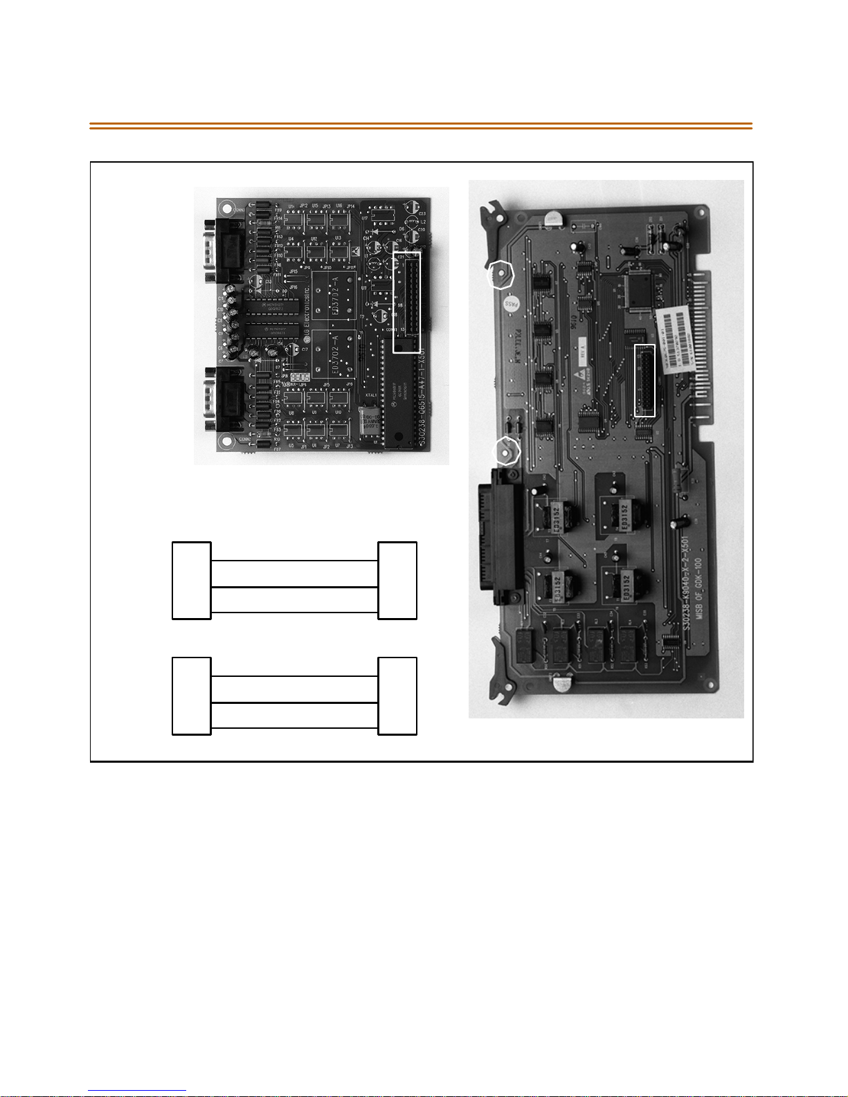
morethan two serial communicationdevices areto beconnected to the
system. If required,install theSIUas shown in Figure 2-14.
Whenusing CO Lines as additional music inputs, keepin mind that the
music source may require a talk battery in series with either TIP or Ring.
This talk battery boosts the signal level sufficiently so that the CO Line
interfacecanread the signal.
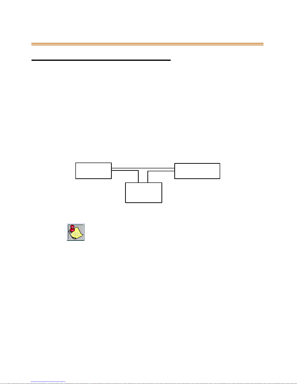
KSU
Talk
Battery
Figure2-13: Talk Battery
TheMISUshouldbeinsertedintoslot#7.
Use extra care when removing RS232 cab les from the MPB or S IU bo ards.
Hold the MPB/MISU card in the card slot before removing the RS232 cable.
Failure to perform th isaction may result in the MPB/ MISU c ard being
pulled from i ts’ slot.
MusicSource
The MISU con sists of:
The Extern al page po rts are provided from the amphenol connector
on the front edge of the MISU. These ports are connected to
transformers, providing a 600 ohm impedance.
Music inputs are provided from the amphenol connector on the front
edg e of the card.
Four independent relay contacts are p rovided through the amph enol
connector on the front edge of the MISU. These contacts are
controlle d by software from entries in the sy stem d atabas e. Control
signals are se nt by the MPB. The outp ut drives the relay coils,
controlling the state of the 1 amp, 24V relay contacts.
Page 51

2-30 Miscellaneous Interface Unit (MISU) Installation
Table 2-2: MISU Wiring
Pair PIN # Color Description Pair PIN # Color Description
1261WH/BL
BL/WH
2272WH/OR
OR/WH
3283WH/GN
GN/WH
4294WH/BN
BN/WH
5305WH/SL
SL/WH
6316RD/BL
BL/RD
7327RD/OR
OR/RD
8338RD/GN
GN/RD
RELAY1T
RELAY1R
RELAY2T
RELAY2R
RELAY3T
RELAY3R
RELAY4T
RELAY4R
14 39
14
15 40
15
16 41
16
17 42
17
18 43
18
19 44
19
20 45
20
21 46
21
BK/BN
BN/BK
BK/SL
SL/BK
YL/BL
BL/YL
YL/OR
OR/YL
YL/GN
GN/YL
YL/BN
BN/YL
YL/SL
SL / Y L
VI/BL
BL/VI
EXP2T
EXP2R
9349RD/BN
BN/RD
10 35
10
11 36
11
12 37
12
13 38
13
RD/SL
SL/RD
BK/BL
BL/BK
BK/OR
OR/BK
BK/GN
GN/BK
BGM/MOH1T
BGM/MOH1R
BGM/MOH2T
BGM/MOH2R
EXP1T
EXP1R
22 47
22
23 48
23
24 49
24
25 50
25
VI/OR
OR/VI
VI/GN
GN/VI
VI/BN
BN/VI
VI /SL
SL/VI
Page 52

Miscellaneous Interface Unit (MISU) Installation 2-31
Installing the Serial Interface Unit (SIU)
1. Unpack th e S IU from it s a ntist atic conduc tive ba g in th e packing box.
There should also be a plastic bag with twoplastic standoffs and two
metal s crews.
2. Push the two standoffs into the holes on the SIU board. (Refer to
Figure 2-14.)
3. Locate the CONN1 connector and the two screw holes (outlined) on
the MISU.
4. Push the SIU board onto the CONN1 connector and be sure it is
seatedcorrectly.
5. From the back side of the MISU board, insert the two metal screws
intothe holes andtighten them into the bottomof each standoff to
secure.
This completes the installation procedure for the SIU.
Page 53
2-32 Miscellaneous Interface Unit (MISU) Installation
CO N N3
CONN1
SIU
CO N N
CO N N2
SIU
RS232C
TERMINAL
9PIN
2(TX)
3(RX)
2(RX)
3(TX)
9PIN
5(GND) 5(GND)
9PIN 25PIN
2(TX)
3(RX)
3(RX)
2(TX)
5(GND) 5(GND)
Figure 2-14: MISU w/SIU Installation
Page 54

CO/PBX Connections 2-33
CO/PBX Connections
There are two types of analog CO/PBX Line interface boards available.
TheseboardsincludetheLoopStartCOLineInterfaceBoard(LCOB),
Direct In-Dial Interface Board (DIDB).
Loop Start CO Interface Board (LCOB)
The Loop Start CO Interface Board supports up to six (6) Loop Start
Central Of fice Lines and ca n be optionally eq uip ped wit h a D TMF Receive
Unit (DTRU) daughter board to detect DTMF for Single Line devices.
Installing the DTRU Module
1. Unpack theDTRU Module from its antistatic conductive bag in the
pack ing box.
2. Locatethe CON1 and CON2 connectors on the DTRUmodule.
3. Locate the CN1 and CN2 connectors on the LCOB (outlined).
4. Position theDTRU module so that the CON2 and CON1 connectors
match up with the CN1 and CN2 connectors on the LCOB
respectively.
5. Push the DTRU module onto these connectors making sure it is
seatedproperly.
Refer to Figure 2-15. This completestheinstallation procedure for the
DTRU Module.
Page 55

2-34 CO/PBX Conne ctions
Table 2-3: LCOB Wiring
LCOB Connector
Connector Pin #
J2 3 Tip 1
2Ring1
4Tip2
1Ring2
J3 3 Tip 3
2Ring3
4Tip4
1Ring4
J4 3 Tip 5
LCOB
Designation
2Ring5
4Tip6
1Ring6
Page 56
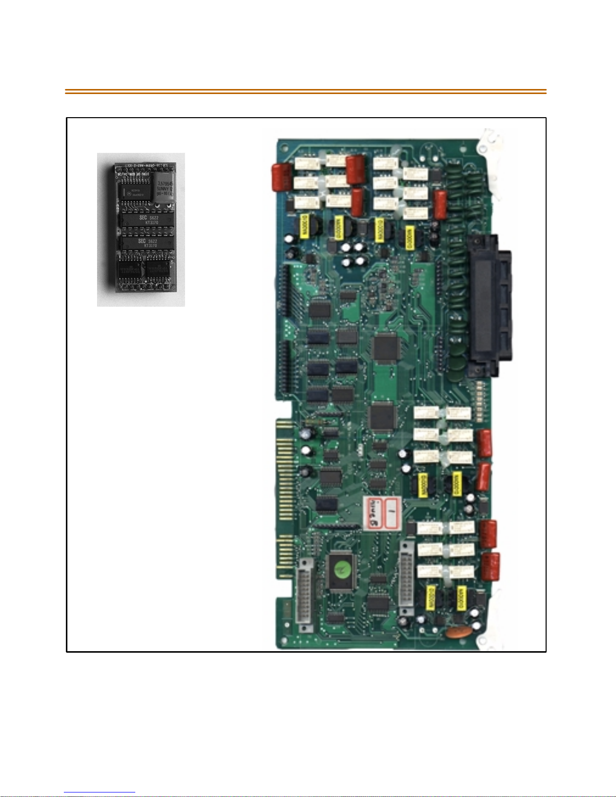
CO/PBX Connections 2-35
CO N 2
DTRU
CON1
Figure2-15: LCOB w/DTRU Installation
Page 57

2-36 CO/PBX Conne ctions
DID Interface Board (DIDB)
The Direct In-Dial Interface board (DIDB) provides four (4) analog DIDCO
interfaceports. The DIDB can be optionallyequipped with aDTMF
Receiver Unit (DTRU) daughter board to detect DTMF tones.
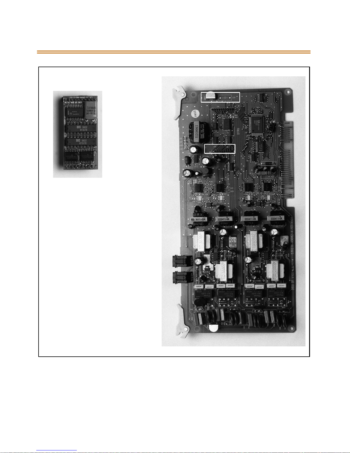
Installing the DTRU Module
1. Unpack theDTRU Module from its antistatic conductive bag in the
pack ing box.
2. Locatethe CON1 and CON2 connectors on the DTRUmodule.
3. Locate the CN1 and CN2 connectors on the LCOB (outlined).
4. Position theDTRU module so that the CON2 and CON1 connectors
match up with the CN1 and CN2 connectors on the LCOB
respectively.
5. Push the DTRU module onto these connectors making sure it is
seatedproperly.
Refer to Figure 2-16. Th is completes th e instal lation p rocedure for the
DTRU Module.
Page 58
CO/PBX Connections 2-37
Table 2 -4: DI DB W irin g
Connections
Designation
Connector Pin #
J3 3 Tip 1
2Ring1
1Tip2
4Ring2
J4 3 Tip 3
2Ring3
1Tip4
4Ring4
Page 59
2-38 CO/PBX Conne ctions
CON2
CN1
DTRU
CN2
CO N 1
Figure 2-16: DIDB w/DTRUInstallation
Page 60
CO/PBX Connections 2-39
T-1 I n t er f ac e B o a rd ( T 1 I B)
The T1IB providesthe T-1(1.544Mbps, 24-VoiceChannel) digitalinterface
circuit, control circuitry, and synchronous clock control circuits. DTMF
tonedetection units canbe installed optionallyon the T1IB.The T1IB has
8 LEDs on the f ront edge of the PCB which indicates errors of T-1 line,
in-use status, and synch ronous clock en abl e status.
The PLLU must b e installed on the MPB for the T-1 ca rd to operat e
pro per ly.
Software 2.1G or ne wer is ne ede d whe n us ing an y T-1 card that contains
1.0G Firmware. Withoutthe newer software, the T-1 card willnot work.
Table 2 -5: T-1 Board L EDS
LED # Function
1 IN USE. At least one of the 24 circuits is in use.
2 RED. T1IB is in REd alarm due to any alarm.
3 H/W TEST. Normal call p rocessi ng is n ot available.
4 BLUE. T1IB has detected RX_BLUE alarm.
5 YELLOW: T1IB has detected RX_YELLOW alarm.
6 OOF. T1I B i s Out of F rame synchron ization.
7 RCL. T1IB receives Carrier Loss (unplugged from the
cable)
8 CLOCK. Clock Enable/Disable
The T1IB contains 2 switches (SW1 and SW3) and 3 connectors (CON1,
CON2 and CON3). The clock selection switch is used for control
synchronous clock. The L ine Build-Out switch is controlled by distance
between the Triad 1/2 Systems and a CSU a nd S W1 #4 is used for
loopback control.
Page 61
2-40 CO/PBX Conne ctions
The system can be equipped with two (2) T-1 Interface Boards and the
T1 IB can b e instal led in Sl ots 0 thru 2 in the Triad 1 Basic KSU, while the
T1 IB can b e instal led in Sl ots 0 thru 5 in the Triad 2 Basic KSU. ThePhase
Locked Loop Unit (PLLU) must be installed on the MPB when the T1IB is
installed. The DTMF4-A board which contains 4 DTMF receivers can be
optionally installed on the T1IB.
The clock control cable should be connected by daisy-chain methodlike
Figure 2-18 when more than one T1IB boards are installed. When the
clock control cable of the T1IB is connected by daisy-chain method, the
clock selection switch of the first T1IB must be placed in the Enable
position and the other board should be placed in the Disable position.
The Line Build- Out sw itch must be selected by distance between th e
Triad 1/2 Systems anda CSU and theswitchselection as indicatedinthe
following chart. If the CSU is located near the KSU, all L BO switches
should be ON.
The S W1 switch #4 of th e L ine Build- Out s witch is use d for LoopBack
control. Its switch is used only for hardware test and must be placed in
the ON position for n ormal operation.
Table 2 -6: T-1 O rdering Information
T-1 Ordering Information
RingerEquivalent Number: 6.0P
Faci lit y Line I nter fa ce: 04DU9-B
Jack Type: RJ48C
Table 2 -7: T- 1 Sw itc h Positions
Distance
1234
0 to 133feet on on on on
133 to 266 feet off on on on
266to 399 feet on off on on
Switc h#
399to 533 feet off off on on
533to 655 feet on on off on
Page 62

CO/PBX Connections 2-41
This board supports s tandard D4 f raming format with robbed bit
signaling. Extended Super Frame (ESF) format is also supported.
The boa rd requi res a n ex ternal CSU uni t.
The T-1 board can accept two (2) DTMF4-A units in a daug hter board
type arrangement. Each unit has 4 DTMF Receivers installed on it.
This board can be installed on the SL IB, and T1IB boards.
The board hasa 15-pin D Sub connector for connection to a CSU unit.
The card ejector tabs are color coded white.
Functionality Description
Automatic Number Identification(ANI) informationfromthe
carrier is treated ex actly the same as an inbo und ICLID (Caller ID)
number. Calls can be routed, placed in the Un answered Call Tab le,
sent out to the CTI Module port on a keyset, and run through the
Number To Name Translation Table. The Triad 2 system provides call
progress tones in the same manner as ICLID.
Dialed Number Identification Service (DNIS) inf ormation f rom the
carrier istreated using DIDline rules. DNIS calls arerouted based on
the D ID Routing Ta bl e.
ANI/DNIS is a combined format, where the system waits for the ANI/
DNIS informationfrom the carrier. When it is received,the system
routes the call using ICLID processing.Ifthisinformation is not found
in the ICLI D Route Tabl es, t he DNI S inf orm ation i s co mpared to th e
DIDtablefora match.Thecall is then routedbasedontheDID tables.
If a match is not found on either theANI or DNIS num ber, the call is
routed bas ed on normal CO line operation (CO Ringing Assignments).
Page 63
2-42 CO/PBX Conne ctions
The following table summarizes the operation of the system.
Ta b l e 2 - 8 : C a l l R o u t i n g C r i t e r i a
ANI DNIS Operation
N N Callsrouted based on normal CO operation(CORing Assignments.
N Y Calls r outed based on DID tables wi th DID operatio n.
Y N Calls r outed based on ICLID routing and ICLID operation.
Y* Y Calls r outed on ICLID first, if n o rout e is found, t he DNIS digits are
compared to the DID table. If n o route is found in the DID table the
cal l is routed based on CO line R inging Assignments.
*If both ANI and DNIScalls are routed--the followingtablesummarizes what is displayedat the phone.
The T-1 card accepts ANI/DNIS informa tion in a DTMF format on ly. So me carrier s do not
provide ANI or ANI/DNIS in a D TMF format .Con sult you r local carr ier for a vailabl e
options.
Table 2-9: Call Routing Display Format
Route
Found
Ty pe of
Display
Format
ICLID ICLID ANI number placed in the 14-character numberfield,
the DNIS number followed bythe name programmed
inICLIDtranslationtable placed in the 24-character
name field.
DID ICLID ANI number placed in 14-character number field. DNIS
number followedby programmed name fromtheDID
tables in 24-character name field.
NONE ICLID ANI number placed in 14-character number fieldand
the DNIS number is placed in the 24-character name
field.
Page 64

CO/PBX Connections 2-43
T-1 Ordering Information: When ordering aT-1 circuit from a carrier,
request eitherD4 framing and AlternateMark Inversion (AMI) Line coding
using thesuperframe(SF) or theExtendedSuperframe(ESF-B8ZS) format.
The following areadditional orderinginformation specifications:
Table 2 -10 : T-1 Order ing S pecif ications
If o rd e r in g …
ANI/DNIS/
DID/TIE
Ground Start Signaling*
Loop Start/
Circ uit In for mati on 2 wire 2 wi re
Supervisory Signalin g TIE Loop or Ground
Address Signaling DTMF DTMF
Start Dial Indicator Wink Start DialTone
* ANI/DNIS not avai lable on Loop/Ground start si gnaling. If Loop Start signaling protocol is ordered, the
CentralO ffice does not provide Disconnect Supervision.Howeverif TIE signaling protocol is ordered,
disconnect supervision is provided. The switching equipmentprocesses DNIS numbers received from the
T-1 ci rcuit depending on the trunk simul ation.
Page 65
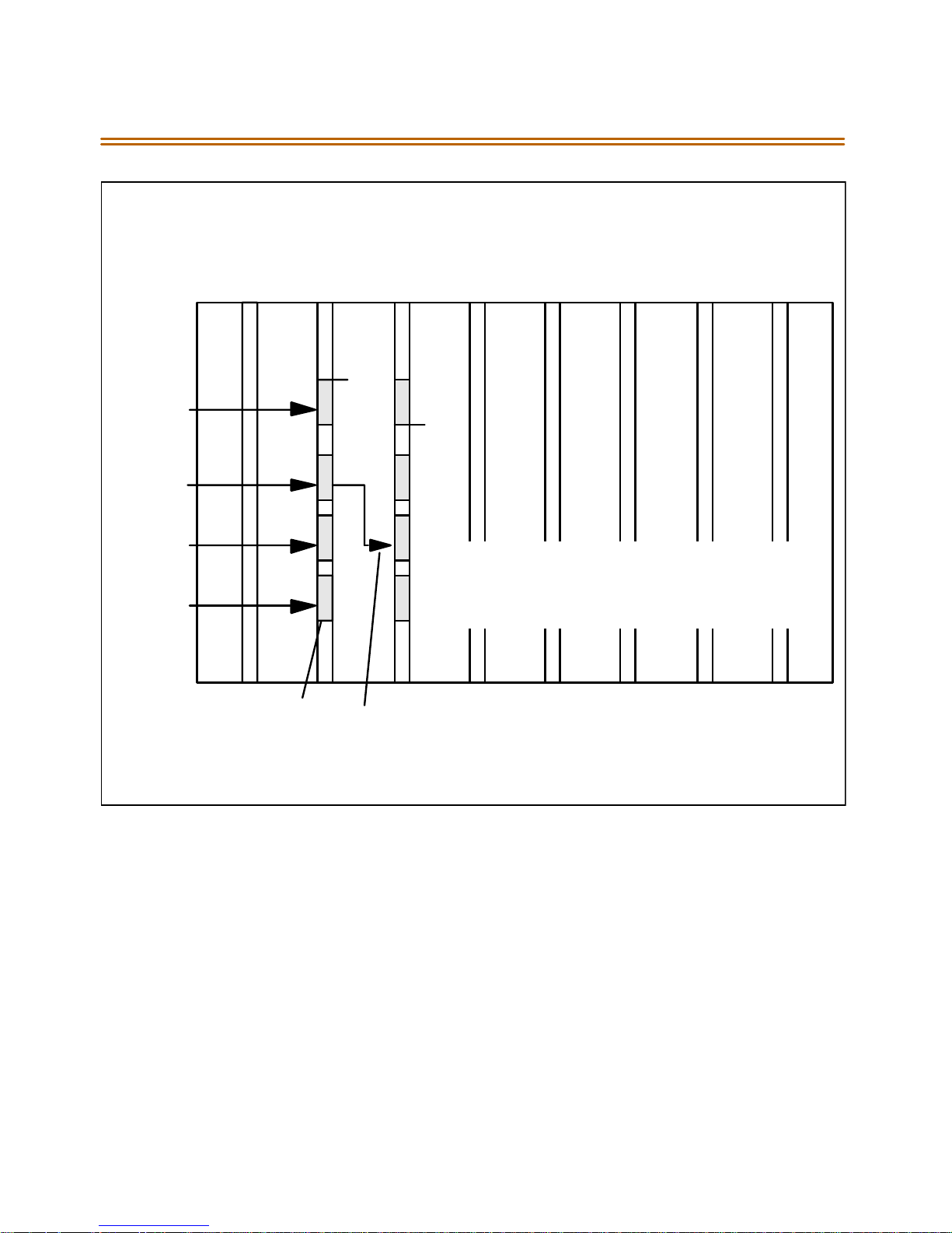
2-44 CO/PBX Conne ctions
MULTIPLE CARD ARRANGEMENT
1
T1-2
UP
SW-3
CT R L
CL KO U T
CT R L
CL K IN
CO N 3
T-1 Lines from Telco Clock Cable
T1-3 4 5 6 7 8
DN
In the case of a Master system, the clock
cable does notgetconnected and SW3 on
all T-1 Boards is in the down posi tion. Two
(2) T-1 Cards maximum in the system.
Figure 2-17: T-1Clock Connect CableInstallation (Multiple Cards)
Page 66
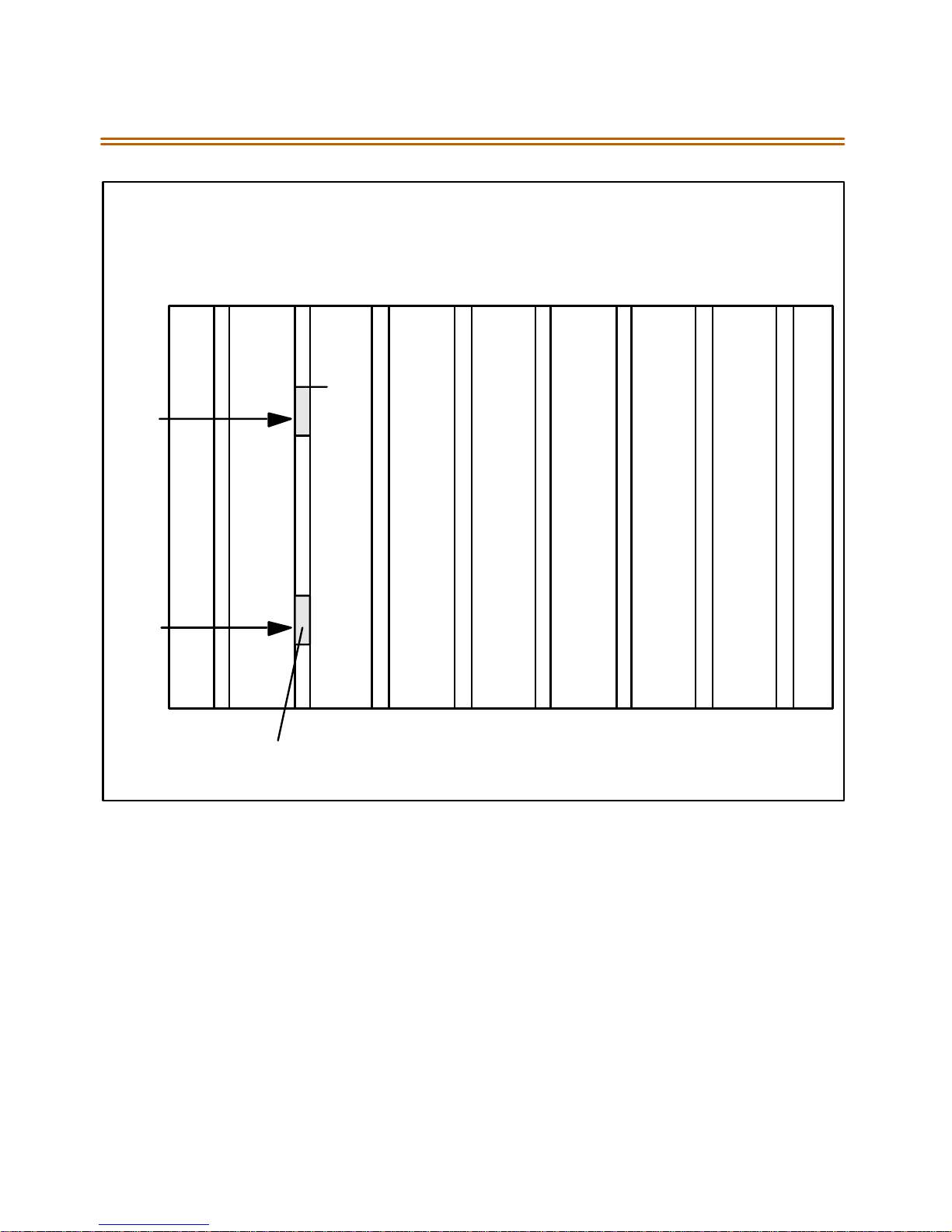
CO/PBX Connections 2-45
SINGLE CARDARRANGEMENT
SW-3
CON3
1
T1-2 T1-3 4 5 6 7 8
UP
T-1 Lines from Telco
Figure 2-18: T-1 Clock Connect Cable Installation (Single Card)
Page 67

2-46 CO/PBX Conne ctions
Installing the DTMF-A Modules
1. Unpack the DTMF-A Modules fromtheirantistatic conductive bags in
the p acki ng b oxe s.
2. Locate the CONN5 and CONN6 connectors on the DTMF-A modules.
3. Locate the CON4, CON5, CON8 and CON9 connectors on the T1IB
(outlined).
4. Position one of the DTMF-A modules so that the CONN5 and CONN6
connectors match up with the CON8 and CON9 connectors on the
T1IBrespectively.
5. Push the DTMF-A module onto these connectors making sure it is
seatedproperly.
6. Position the second DTMF-A module so that the CONN5 and CONN6
connectors match up with the CON4 and CON5 connectors on the
T1IBrespectively.
7. Push the DTMF-A module onto these connectors making sure it is
seatedproperly.
Refer to Figure 2-19. This completesthe installation procedure for the
DTMF-AModules.
Page 68
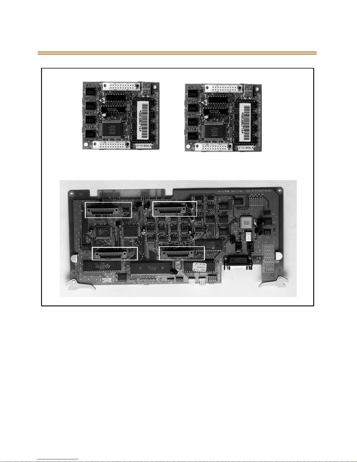
CO/PBX Connections 2-47
A
-
D
F
M
T
D
A
-
F
M
T
CONN6
CO N 9
CO N 8
CO N 5
CO N 4
CONN6
Figure2-19: T1IB w/DTMF4_A Module Installation
Page 69

2-48 CO/PBX Conne ctions
Primary Rate Interface Board (PRIB)
This interface provides one Primary Rate Interface circuit. Each circuit
contains 23 bearer and one data channel (23B+D). When a PRIB card is
programmed into the Triad 1/2 system, the system interprets all
B channels as trunks. Thus, one PRIB which contains 23B+D circuits
provides 23 line appearances to the Triad 1/2 system. A ma ximum of two
PRIB boards may be installed into the system. The PRIB card uses 24 time
slots when installed.
The PRIB must beused in conjunction with a Channel Service Unit (CSU).
Connection is made via a DB15 from the PRIB to the CSU.
The PRIBaccepts twoDTMF-A boards.
When ordering PRI lines from the telephone company, specify ESF
framing and B8ZSline coding. PRI only supports National ISDN 2 (NI-2).
No other standards are supported.
Vodavi hassuccessfullyintegrateditsPRIISDNwiththeLucent 5ESS,
Si em e ns , St r om bu r g Ca rl so n, a n d t he DM S 100 C en t ral O f f ice s. V od av i
ISDN should work with all C ent ral O ffice switc hes, bu t this has not b een
verified. Therefore, some delays in service maybe experienced.
Installation
1. Insert the PRIB card(s) into thedesired BKSU card slot(s). Up totwo
PRIB ca rds can be installed in a system (Slots 1 and 2 on Triad 1 an d
slots 1-5 on Triad 2).
2. If installinga singlePRIB, set SW2 to the ON position.
If multiple PRIBs are being installed,set SW2 to the ON position on
the first car d a nd S W2 on a ll other cards to th e O FF pos ition .
The PRIB comes with a clock cable. This cable is used when multiple
PRIB and/or digital trunk cards are to be installed in the system. The
clock cable is supplied wi th each PRIB.
3. Connect the DB15 cable from the PRIB to the channel service unit
(CSU).
4. Connect the network cable from thechannel service unit to the
network.
5. Refer to ISDN and T1 Clocking (later in this section) forclarification on
clocking and cabling when combining BRIB, PRIB, and T1 cards in one
KSU.
Page 70
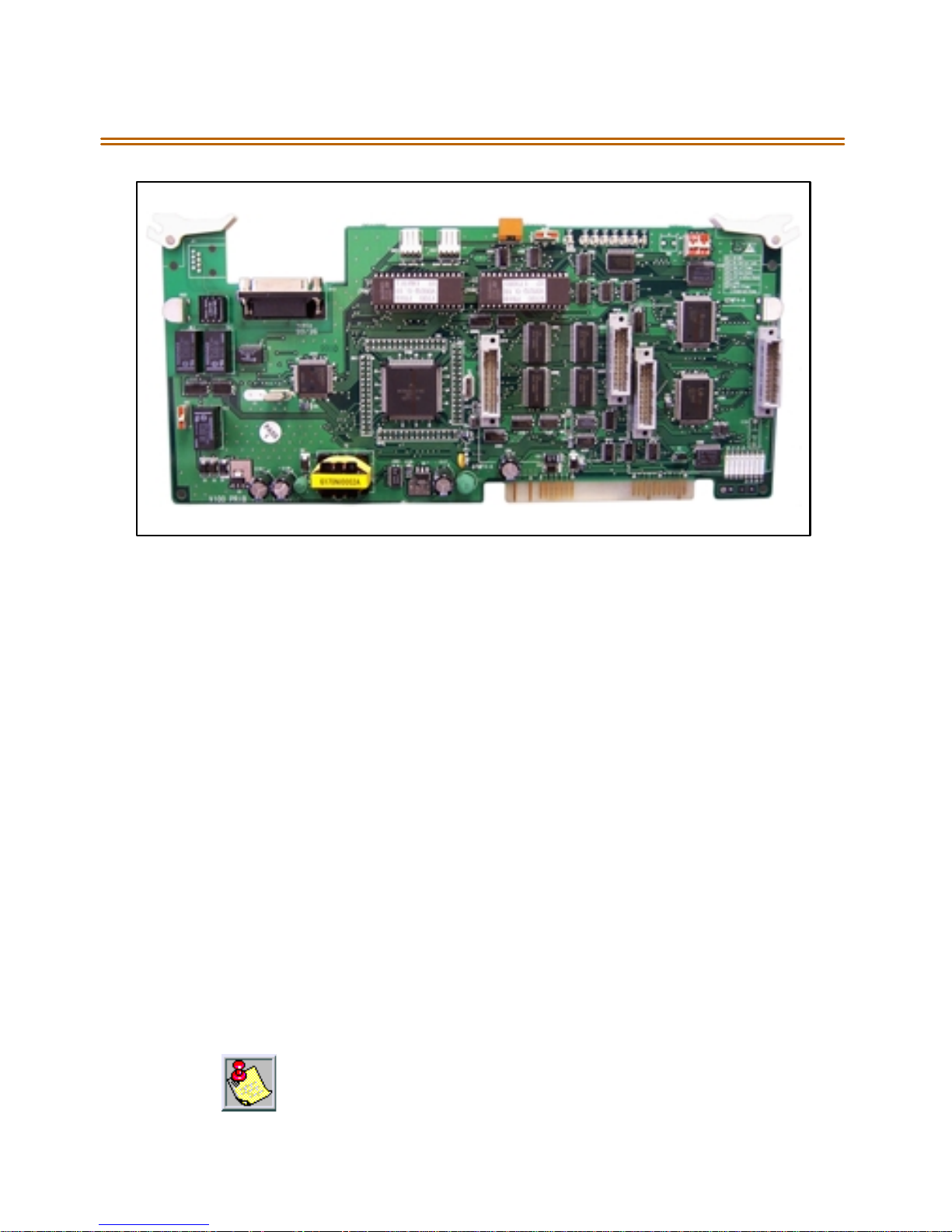
CO/PBX Connections 2-49
Figure 2-20: PRIB ( Primary Rate Interface Board)
The PRIB is offered as a stand-alone card or as a kit which includes the
PRIB, CSU, and cables.
Basic Rate Interface Board (BRIB)
This interface provides four Basic Rate Interfacecircuits. Each circuit is
comprised of two bearer (64Kbps each) and one data (16Kbps) channels
(2B+D). When a BRIB is programmed into the Triad 1/2 system, the system
interprets all B channels as trunks. Thus, one BRIB which contains four
2B+ D circuits p rov ides eight line appearan ces to the Triad 1/2 sys tem. A
maximumoffiveBRIBscanbeinstalledintothesystem(40Bchannels).
The BRIB uses the U interface of the BRI standard. Connection to the
network is made via RJ45 connectors on the front edge of the board. No
NT1 device is required to connect to the central office. The BRIB card uses
eight time slots when ins talled.
When ordering BRI lines from the telephone company, specify
Cap ability P as the ordering cod e. National IS DN 1 (N I-1) is sup ported. No
other standards are supported.
Vodavi hassuccessfullyintegrateditsBRIISDN with theLucent5ESS
Centra lOffice.Vodavi ISDN should work wit hall Centra lOffice switches,
but th is has not been verified. Therefore, some dela ys in service may b e
ex per ien ced.
Page 71
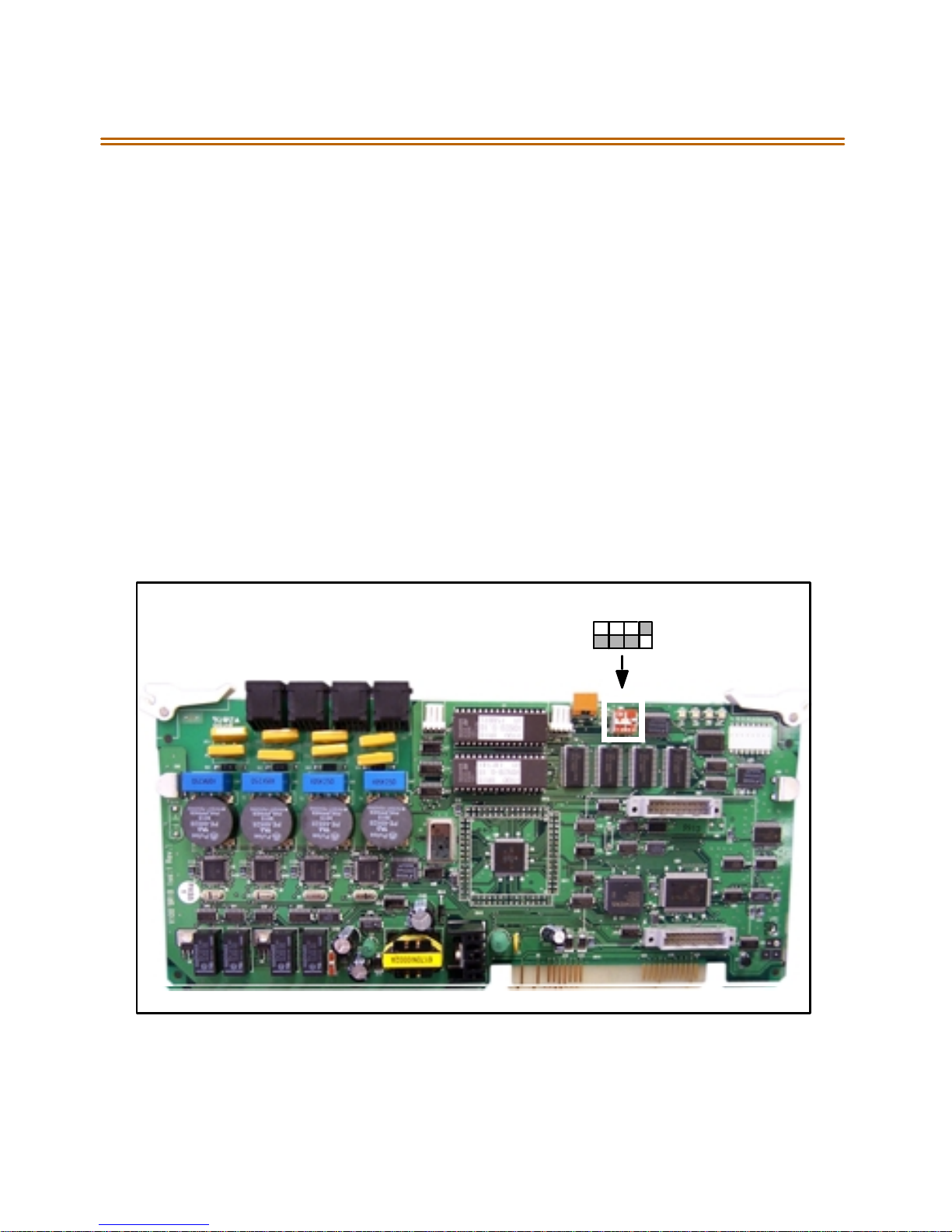
2-50 CO/PBX Conne ctions
Installation
1. Insert the BRIB card(s)into the desired BKSUcard slot(s).
(Slots1and2onTriad 1and slots 1-5 on Triad 2)
If installing a singleBRIB,set switch 4 on SW2 to the ON position.
If multiple BRIB cards are being installed, set switch 4 on SW2 to
theONpositiononthefirstcardandswitch4onSW2onallother
cardsto the OFFposition. Switch 4on SW2 determines ifthe
board is the Master Clock source for any digital trunk cards in the
system. Onlyone Master Sourcemust be enabled in thesystem.
If installing a BRIB in a system that also has T1 or PRIB boards, use
either the T1 or PRIB card as the Mas ter C lock a nd set all BRIB S W2
switch 4s to OFF.
2. Refer to ISDN and T1 Clocking (later in this section) forclarification on
clocking and cabling when combining BRIB, PRIB, and T1 cards in one
KSU.
SW2SWITCHES:
2341
Figure2-21: BRIB (Basis Rate InterfaceBoard)
ON
OFF
Page 72

CO/PBX Connections 2-51
Electronic Key Telephone Service
Electronic key telephone service (EKTS) is a feature that can be provided
onBRI ISDN to simulatestandardanalog DID lines.Thisallows several
different numbers to be shared by a single BRI circuit.
Due to the decline in telephony tariffs, there is an increasing demand for
BRI ISDNfeatures.A BRI circuit allows twosimultaneous calls tobe
handled, dueto its technical specification. BRI circuits have two
B-Channels at 64 kilobytes per second and one D-Channel at 16kilobytes
per s econd. The Bearer (B) Chann els are d esigned for PCM (voice) and the
Data (D) Channel is designed to carry information specific to each
incoming and/or outgoing call.
TheEKTSfeatureallowsasingleISDNServiceProfileIdentifier(SPID)or
B-Channelto support multiple directory numbers. A SPIDis anumber
that telephone company switching equipment usesto track
configuration information for each terminal adapter connected to an
ISDN telephone line. The telephone company should provide SPIDs at
thesametimethattheISDNdirectorynumbersareassigned.Adirectory
number is another term for a telephone number.
If an application requires EKTS, be aware that BRI ISDN handles a busy
number differently than a DID circuit. When the called number is busy,
BRI will issue a busy signal,but a DID circuit willringanother line in the
circuit. The busy signal is provided by the telephone company, therefore
the call i s not p re sented t o t he Voda vi te lephone s wit ch a nd i t is not
forwarded to voicemail. For example, a caller dials 480-443-6000 and is
connected to the extension. While the first calleris still connected, a
second caller dials the same number. The second callerwill receive abusy
signal that isprovidedby the telephone company.
In a normal BRI application, two nu mbers are assigned to each BRI circuit,
which consists of 2 channels. There can be amaximumof 4 circuits
equipped to handle 8 channels per BRIB. This is a direct number-tochannel relationship without hunting capability. Most circuit providers
offer an optional “hunting”feature cap ability on BRI circuits. This optional
feature allows numbers to hunt for idle channels on the BRIB up to a
maximum of 8 channels per BRIB, assuming four BRIcircuits were
installed. In EKTS app lications, you can h ave a maximum of 64 DID
numbers hunt to one BRIB. Hunting cannot be accomplished between
BRIBs, nor will the hunting feature allow calls to be routed to a busy DID
number.
Page 73

2-52 CO/PBX Conne ctions
Conditions
BRI EKTS su pport is ava ilable in Vodavi telephone systems with software
version 3.0G and higher.
LikeDID,EKTS can be programmed to route calls using upto 7 digits.By
default, onlythe last threedigitsare analyzed for routing.
EKTS does not require a line a ppearance on a specific telephone beca use
the BRI terminates directly intothe KSU.
Vodav i supports Basic EKTS. The EKTS ca ching option is not supported by
Vodavi. Caching is normally used when an ISDN telephone instrument is
used on the customer premise.
ISDN and T1 Clocking
WhencombiningBRIB,PRIB,and T1 cardsin one KSU,specificsettings
and cabling are important for p roper clocking. The Phas e Lock Loop Unit
(PLLU) synchronizes the clocking from the Central Office to the clocking
oftheKSU.Popping,crackling,droppedcalls,andone-waytransmission
ar e u sually at tribut ed to the clocking not be ing synch roni zed cor rect ly.
Examples - Settings and Cabling
The following examples clarify the clocking and cabling for these cards:
When the switch is in the “up” positi on, it should be con si der ed “ON ”.
When the switc h isin the “do wn”position, it should be con si der ed “OFF”.
The ca ble c onnecti on foll ows the s ame logi c - “up ”is clock ou tsi de (ON)
and “down” is clock insi de (OFF). ON me ans th atclockin gis c omingfrom
outsid e the KSU a nd O FF mean s that clo cki ng is comin g from ins ide the
KSU.
Page 74
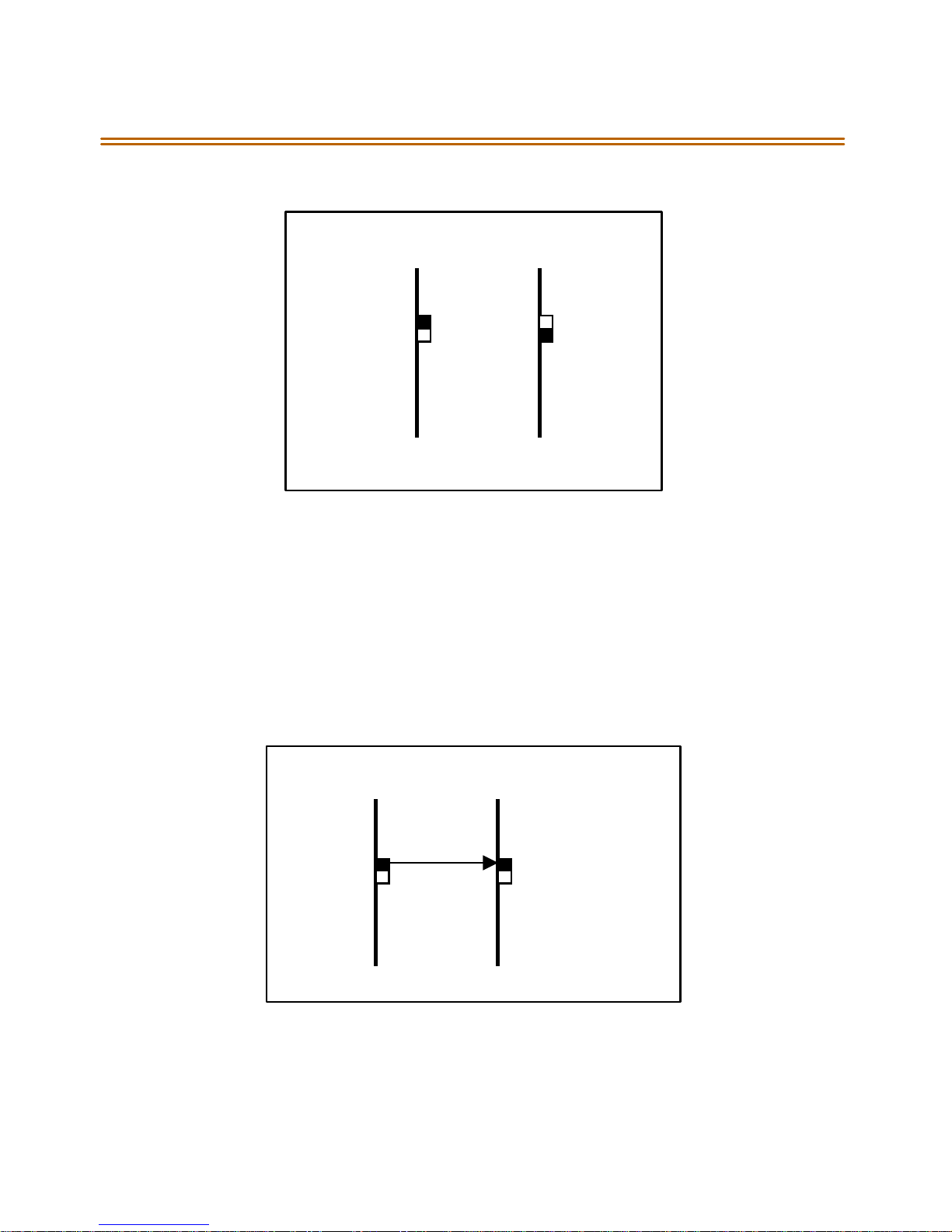
CO/PBX Connections 2-53
(1) T1IB and (1)PRIB
T1IB PRIB
SW3 On SW2 Off
If both cards in a phone switch are connected to a telephone company
clock (not point-to-point T1), put the T1 clock switch in the enable
position (UP) to allow it to receive clocking from the telephone company
directly, and do not install the clock cable. Set the PRIB clock switch in the
disable position (OFF),which allowsthe PRIB to synchronize its timing off
ofthe backplane (from the T1 clocking). If the T1 is a point-to-point T1,
se t the PRI B in th e enab le pos ition (ON ), t he T1 i n t he di sab le position
(OFF), and do not install the clock cable.
(1) PRIB and (1) BRIB
PRIB BRIB
Sw2 On Switch 4, SW2 On
Install with the cable and set both PRIB and BRIB switches to the enable
position (ON).
Page 75
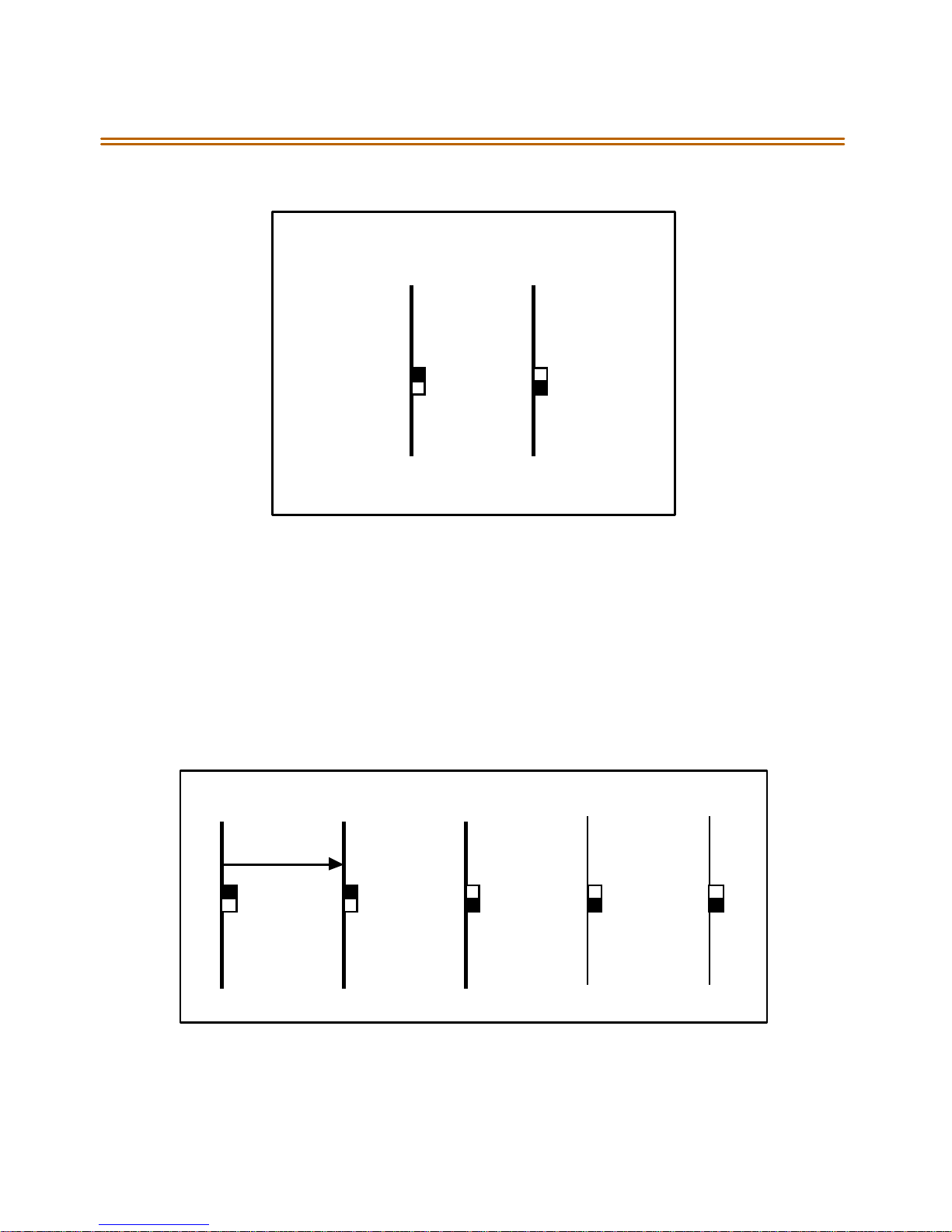
2-54 CO/PBX Conne ctions
(1) T1IB and (1) BRIB
T1IB B RIB
SW3 On Switch 4, SW2 Off
If both cards in a phone switch are connected to a telephone company
clock (not point-to-point T1), put the T1 clock switch in the enable
position (ON) to allow it to receiveclocking from the telephone company
directly. Do not install the clock cable. Set the BRIB clock switch in the
disable position (OFF),which allowsthe BRIB to synchronizeits timingoff
ofthe backplane (from the T1 clocking). If the T1 is a point-to-point T1,
set the BRIB to the enable position (ON), the T1 in the disable position
(OFF), and do not install the clock table.
(2) PRIBsand (3) T1IBs
PRIB1 PRIB2 T1IB 1 T1 IB2 T1IB3
SW2 On SW2 On SW3 Off SW3 Off SW3 Off
The clock cable should be connected to the OUT position on the
connector on the PRIB1. The clock cable should be connected to the IN
position on PRIB2. SW2 of the PRIB1 and PRIB2 should be placed in the
Page 76
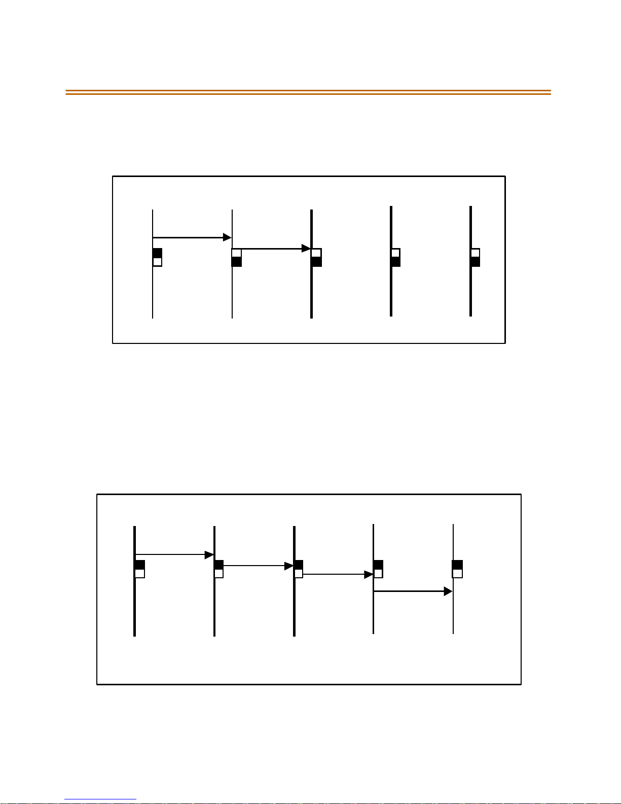
CO/PBX Connections 2-55
ON position. The three T1IBsare not connected with the clock control
cable and SW3 on these boards should be in the OFF pos ition.
(3) T1IBs and (2) PRIBs
T1IB1 T1IB2 T1IB3 PRIB1 PRIB2
SW 3 O n SW3 Off SW3 Off SW2 Off SW2 Off
The clock cable should be connected to the OUT position on the cable
connector on the T1IB and connected to the IN position on the connector
on the T1IB2. The clock cable should be connected to the OUT position
on T1IB2 and connected to the IN position on the T1IB3. SW3 of T1IB1
shouldbeplaced in the ONposition, withSW3 onT1IB2 and T1IB3 being
OFF. The two PRIBs are not connected with clock control cables, and SW2
on the PRIBs should be in the OFF position.
(3) PRIBsand (2) BRIBs
PRIB1 PRIB2 PRIB3 BRIB1 BR IB2
SW2 On SW2 On SW2 On Switch 4, SW2 On Switch 4, SW2 On
TheclockcableshouldbeconnectedfromtheOUTpositionofthePRIB1
to the IN connectors of all the cards and all clock switches should be in
the ON position.
Page 77
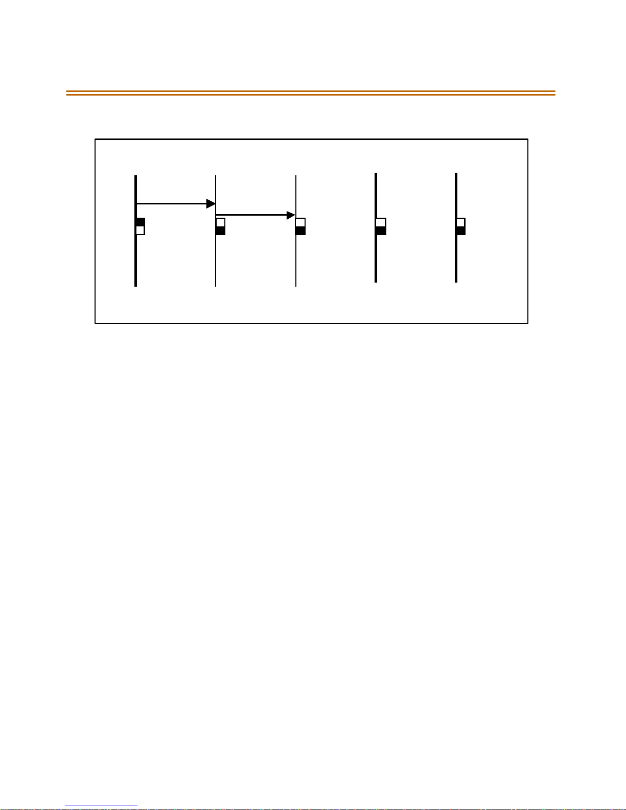
2-56 CO/PBX Conne ctions
(3) T1IBs and (2) BRIBs
T1IB1 T1IB2 T1I B3 B RIB1 BRIB2
SW3 On SW3 Off SW3 Off Sw itc h 4, SW2 O ff Switch 4, SW2 Off
TheclockOUTcablefromT1IB1shouldbeconnectedtotheclockIN
cable of the T1IB2 and the clock OUT cable from T1IB2 should be
connected to the clock IN cable of T1IB3. SW3 ofT1IB1 should be in the
ON position, and SW3 ofT1IB2 and T1IB3 should be inthe OFFposition.
The two BRIBs are not connected with clock control cables and SW2 of
the BRIB cards are placed in the OFF position.
Page 78

Station Connections 2 -57
Sta tion Conn ectio ns
The system can be equipped with any combination of the four s tation
boards; DTIB12, DTIB24, ETIB and S LIB6. The station interface boards can
be installed in any card slot in the BKSU and EKSU, except for MPB slot of
the BKSU. As a d efault, t he sof twa re allo ca tes slo ts 1 th rough 5 of t he
BKSU and 9 through 10 of the EKSU forstation interface boards. It is
recommended that slots beginning from SLOT #1 be used for station
interface boards. Also, si nce the first port of the DTIB is the database
access port (the only port which enables Admin programming), it is
strongly recommended that a DTIB be installed in the SLOT #1 and a
Digital Keyset w/LCD be connected to the first port.
Electronic Telephone Interface Board (ETIB)
The E TIB board prov ides the interface to twelve (12) el ectron ic
telephones or DSS/DTS terminals. The card has one LED indicator for
off-hook/in use status. The ETIB card extractors are color coded green.
There is o ne 50-pin female amphenol connectors labeled Conn2 located
onthe front ofthe card. This allowsthe system to be cabled to the main
distribution frame (MDF). 25-pair telephone cabling must be prepared
with mating connectors to extend the interface circuits to the MDF. The
cables should be routed through the cable clamps at the bottom of th e
KSU to the MDF.Thesecables are thenterminated on industry standard
66 M 1- 50 t yp e p u nchdo wn con n ec t or bl ock s. It i s r e co m m end ed tha t
66M1-50 split blocks with bridging clips be used to simplif y
troubl eshoot ing and to quickly isolat e faults.
Only DTIB typestations can be used for Databaseprogramming.
Page 79
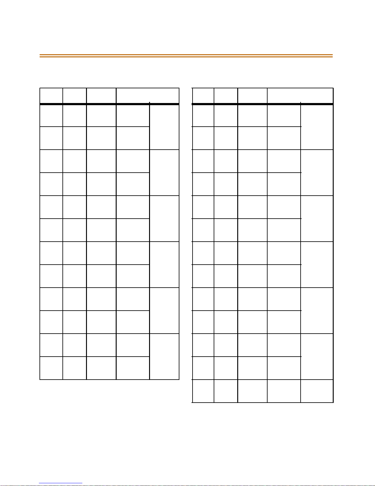
2-58 Station Connections
Table 2- 11 : ETIB W iring
Pair PIN # Color Description Pair PIN # Color Description
1261WH/BL
BL/WH
2272WH/OR
OR/WH
3283WH/GN
GN/WH
4294WH/BN
BN/WH
5305WH/SL
SL/WH
6316RD/BL
BL/RD
7327RD/OR
OR/RD
8338RD/GN
GN/RD
VT- 1
VR -1
DT-1
DR-1
VT- 2
VR -2
DT-2
DR-2
VT- 3
VR -3
DT-3
DR-3
VT- 4
VR -4
DT-4
DR-4
CKT1 13 38
13
14 39
14
CKT2 15 40
15
16 41
16
CKT3 17 42
17
18 43
18
CKT4 19 44
19
20 45
20
BK/GN
GN/BK
BK/BN
BN/BK
BK/SL
SL/BK
YL/BL
BL/YL
YL/OR
OR/YL
YL/GN
GN/YL
YL/BN
BN/YL
YL/SL
SL/YL
VT- 7
VR -7
DT-7
DR-7
VT- 8
VR -8
DT-8
DR-8
VT- 9
VR -9
DT-9
DR-9
VT-10
VR-10
DT- 10
DR -1 0
CKT7
CKT8
CKT9
CKT10
9349RD/BN
BN/RD
10 35
10
11 36
11
12 37
12
RD/SL
SL/RD
BK/BL
BL/BK
BK/OR
OR/BK
VT- 5
VR -5
DT-5
DR-5
VT- 6
VR -6
DT-6
DR-6
CKT5 21 46
21
22 47
22
CKT6 23 48
23
24 49
24
25 50
25
VI /BL
BL/VI
VI /OR
OR/VI
VI/GN
GN/VI
VI /BN
BN/VI
VI/SL
SL/VI
VT-11
VR-11
DT- 11
DR -1 1
VT-12
VR-12
DT- 12
DR -1 2
CKT11
CKT12
Page 80
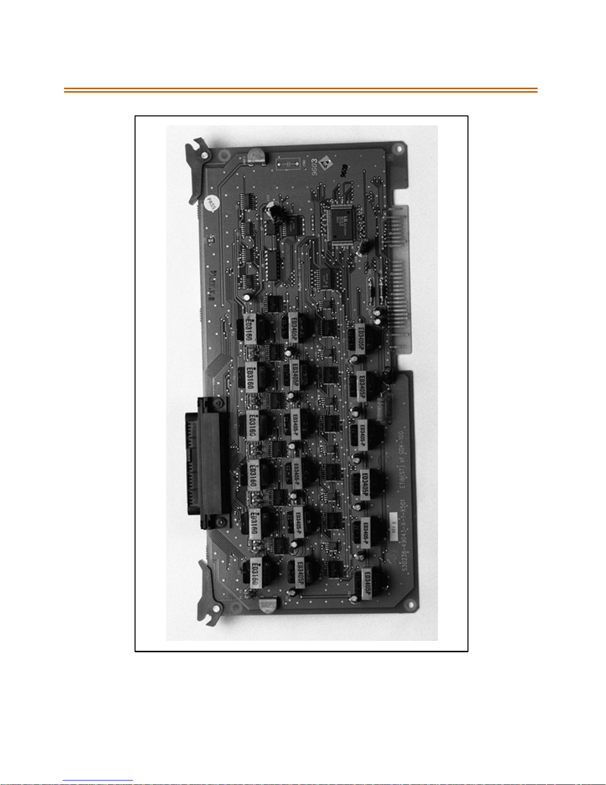
Station Connections 2 -59
Figure 2-22: Electronic Telephone Interface Board (ETIB)
Page 81
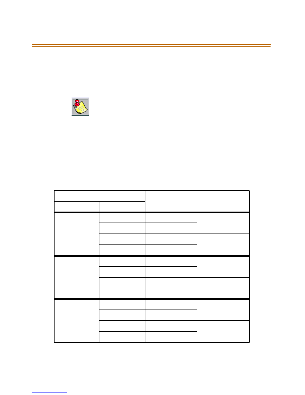
2-60 Station Connections
Single Line Interface Board (SLIB)
This board providesthe interface to six (6) 2500 type telephones. The
SLIB signals interface with mechanical 90V ringers and lights 90V
messagewaitinglampson2500setsasdesired.
Only one SLT station is all owed per d igit al extension n umber. It is not
possible to bridge digital station p orts so that an ext ension number ma y
appear in more than one location.
The station connections arevia three (3) Modular (RJ14 type) connectors
located on the front edge of the card. The board can support a DTRU
board and a MSG12 board in a daughter board type arrangement.
The DTRU unit has two (2) DTMF receivers on it and can be installed on
the SLIB board. The DTRU mounts on the SLIB board as a daughter board
ty pe arran gement.
Table 2 -12 : SLIB Wiri ng
SLIBConnector
Connector Pin # 3MConnection 6M Connection
M3 3 Tip 6 Tip 6
2Ring6Ring6
4 Tip 5 Tip 5
1Ring5Ring5
M2 3 Tip 4 Tip 4
2Ring4Ring4
4 Tip 3 Tip 3
1Ring3Ring3
M1 3 Tip 2 Tip 2
2Ring2Ring2
4 Tip 1 Tip 1
1Ring1Ring1
Page 82

Station Connections 2 -61
Installing the DTRU Module
1. Unpack theDTRU Module from its antistatic conductive bag in the
pack ing box.
2. Locatethe CON1 and CON2 connectors on the DTRUmodule.
3. Locate the CONN1 and CONN2 connectors on the SLIB (outlined).
4. Position theDTRU module so that the CON2 and CON1 connectors
match up with the CONN1 and CONN2 connectors on the SLIB
respectively.
5. Push the DTRU module onto these connectors making sure it is
seatedproperly.
Refer to Figure 2-23. This completesthe installation procedure for the
DTRU Module.
Installing the MSGU Board
The MessageWait Lamp Relay Control (MSGU) providesMessage Wait
Lamp Relay Controlfor message lamp singlelinetelephones. The MSGU
board mounts on the S LIB board a s a daughter board type arrangement.
1. Unpack theMSGUModule from its antistatic conductive bag in the
pack ing box.
2. Locate the CONN1 and CONN2 connectors on the MSGU m odule.
3. Locate the CONN3, and CONN4 connectors on the SLIB (outlined).
4. Position the MSGU module so that the CONN1 and CONN2
connectors match up with the CONN3 and CONN4 connectors on the
SLIB respectively.
5. Push the MSGU moduleonto these connec tors making sure it is
seatedproperly.
Refer to Figure 2-23. This completesthe installation procedure for the
MSG U M odu l e.
Page 83

2-62 Station Connections
Ad justi ng Modem Sett ings
When using modems connected to SLT ports on the Triad 1/2/3,thegain
se ttin gs on th e S LT port when usi ng T 1 as acces s t o t he CO s hould be se t
to 0 dB(maximizes modem speed).
COtoSLTCallviaaT1TIETrunk:
1. Access the specific trunk type above.
2. Hookflash and dial 638 8 on the keypad.
3. Hang up.
COtoSLTCallviaaT1Trunk:
1. Access the specific trunk type above.
2. Hookflash and dial 638 6 on the keypad.
3. Hang up.
SLT to SLT Call:
1. Placeanintercomcallfrom1SLTto another.
2. Hookflash and dial 638 5 on the keypad.
3. Hang up.
No adjustment is needed if access to the CO is accomplished by standard
loop/ground start trunk circuits. These trunk types are set to 0 dB by
default.
In all cases the maximum mode m sp eed is not as much as if the modem
were connected directly to the CO line. The system degrades the
connection to the next lower baud rate that the modem supports.
Example: If themodem can achieve 28800 on a direct CO line, the
maximum speed on an SLT port would be 26400.
Testing provesthat a baud rate of 33600 can be achieved with SLT-T1
lines.Typical connectionspeeds with SLT-T1 are 22700-33600. Typical
connection speedswithSLT-Loop/GroundStart are 17400-23800.
All resul tswere obtained using a 56K U.S. RoboticsSport ster modem.
Page 84
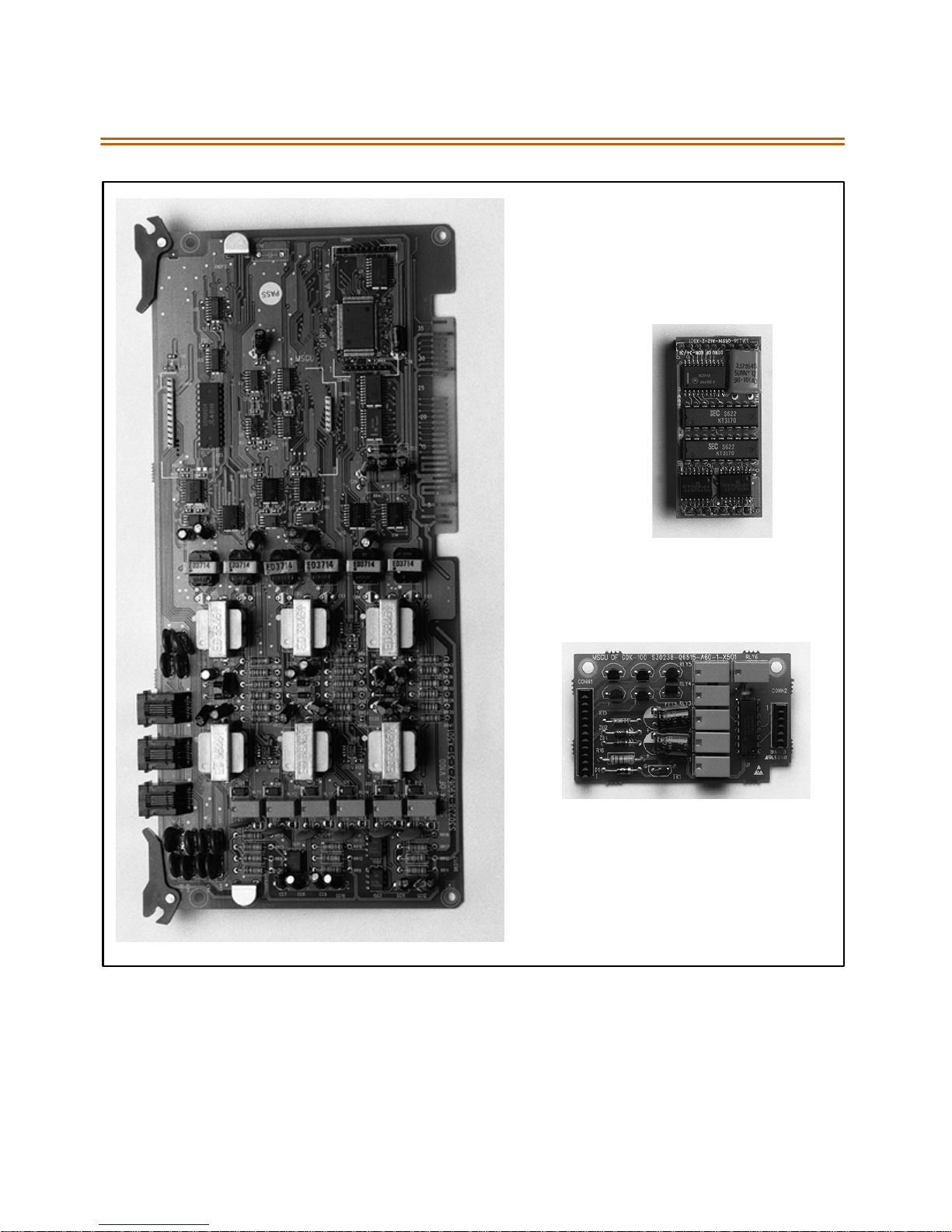
Station Connections 2 -63
CONN1
CO N 2
DTRU
CONN2
CO N N4
CO N N3
CO N 1
MSGU
Figure 2-23: SLIB w/MSGU and DTRU ModuleInstallation
CO N N1
Page 85

2-64 Station Connections
Digital Telephone Interface Board (DTIB)
The DTIB board provides the interfaceto twelve (12) digital telephones.It
is offered in two (2) versions,a 12-circuit anda 24-circuit.The card has
one LED to indicate off-hook/in use status. The DTIB card extractors are
color codedgreen.
Only one stati oni sa llowed perdigitalextension num ber.Itis notpossible
to bridge digital station ports so that an extension number may appear
in m ore than one location.
Cables
There is o ne 50-pin female amphenol connectors labeled Conn2 located
onthe front ofthe card. This allowsthe system to be cabled to the main
distribution frame (MDF).
25-pair telephone cabling must be p repared with mating connectors
to extend the interfacecircuitsto the MDF.
Cables should be routed through the cable clamps at the bottom of
the KSU to the MDF. These cables are then terminated on industry
standard 66M1-50 typ e punchdown conn ector blo cks.
It is recommended that 66M1-50 split blocks with bridging clips b e
used to simplifytroubleshootingandto quicklyisolatefaults.
Page 86
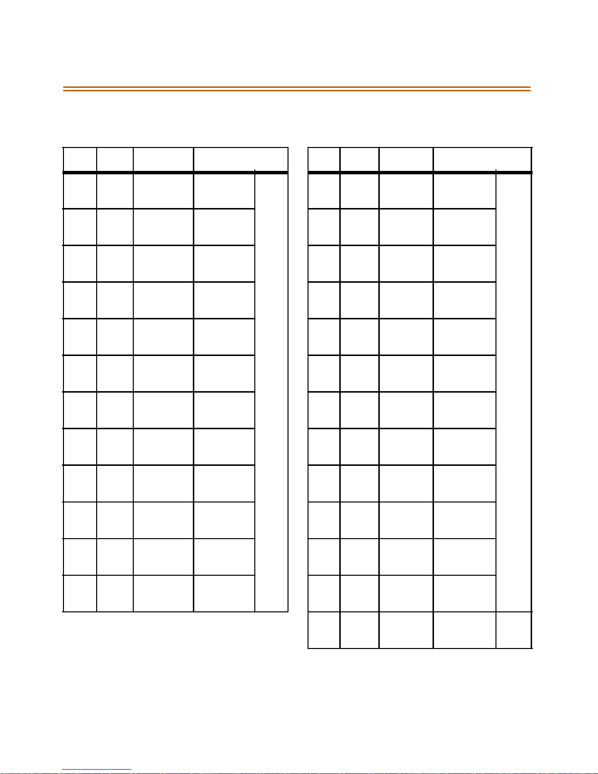
Station Connections 2 -65
Table 2 -13 : DT IB Wiring
P ai r PIN # C olo r D esc r ip t ion Pa ir PI N # C o lo r D es c rip t i on
1261WH/BL
BL/WH
2272WH/OR
OR/WH
3283WH/GN
GN/WH
4294WH/BN
BN/WH
5305WH/SL
SL/WH
6316RD/BL
BL/RD
7327RD/OR
OR/RD
8338RD/GN
GN/RD
DATA-R 1
DATA-T 1
DATA-R 2
DATA-T 2
DATA-R 3
DATA-T 3
DATA-R 4
DATA-T 4
DATA-R 5
DATA-T 5
DATA-R 6
DATA-T 6
DATA-R 7
DATA-T 7
DATA-R 8
DATA-T 8
13 38
13
14 39
14
15 40
15
16 41
16
17 42
17
18 43
18
19 44
19
DTIB12 Station Ports
20 45
20
BK/GN
GN/BK
BK/BN
BN/BK
BK/SL
SL/BK
YL/BL
BL/YL
YL/OR
OR / Y L
YL/GN
GN/YL
YL/BN
BN/YL
YL/SL
SL/YL
DATA-R 1 3
DATA-T 13
DATA-R 1 4
DATA-T 14
DATA-R 1 5
DATA-T 15
DATA-R 1 6
DATA-T 16
DATA-R 1 7
DATA-T 17
DATA-R 1 8
DATA-T 18
DATA-R 1 9
DATA-T 19
DATA-R 2 0
DATA-T 20
DTIB24 Station Ports
9349RD/BN
BN/RD
10 35
10
11 36
11
12 37
12
RD/SL
SL/RD
BK/BL
BL/BK
BK/OR
OR/BK
DATA-R 9
DATA-T 9
DATA-R 10
DATA-T 10
DATA-R 11
DATA-T 11
DATA-R 12
DATA-T 12
21 46
21
22 47
22
23 48
23
24 49
24
25 50
25
VI /BL
BL/VI
VI /OR
OR/VI
VI/GN
GN/VI
VI /BN
BN/VI
VI/SL
SL/VI
DATA-R 2 1
DATA-T 21
DATA-R 2 2
DATA-T 22
DATA-R 2 3
DATA-T 23
DATA-R 2 4
DATA-T 24
Page 87
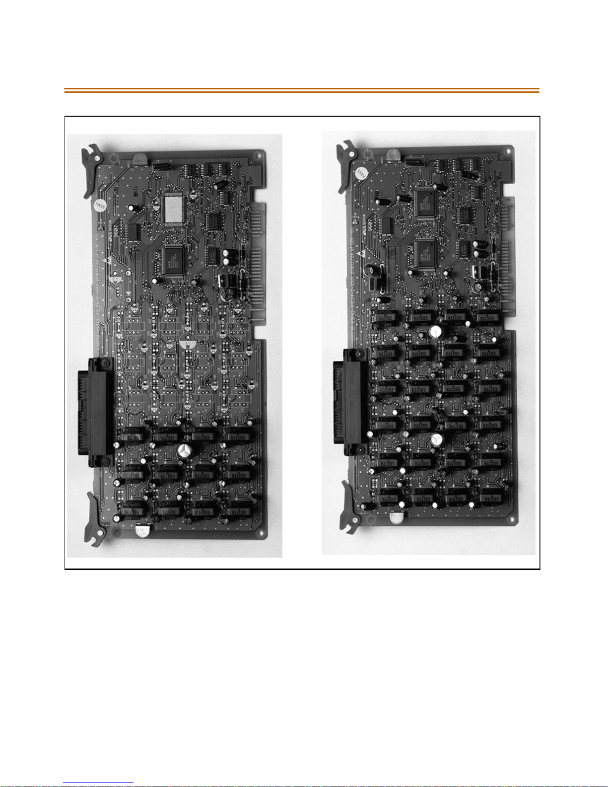
2-66 Station Connections
Figure 2-24: Digital Telephone Interface Board (DTIB) Installation
Page 88
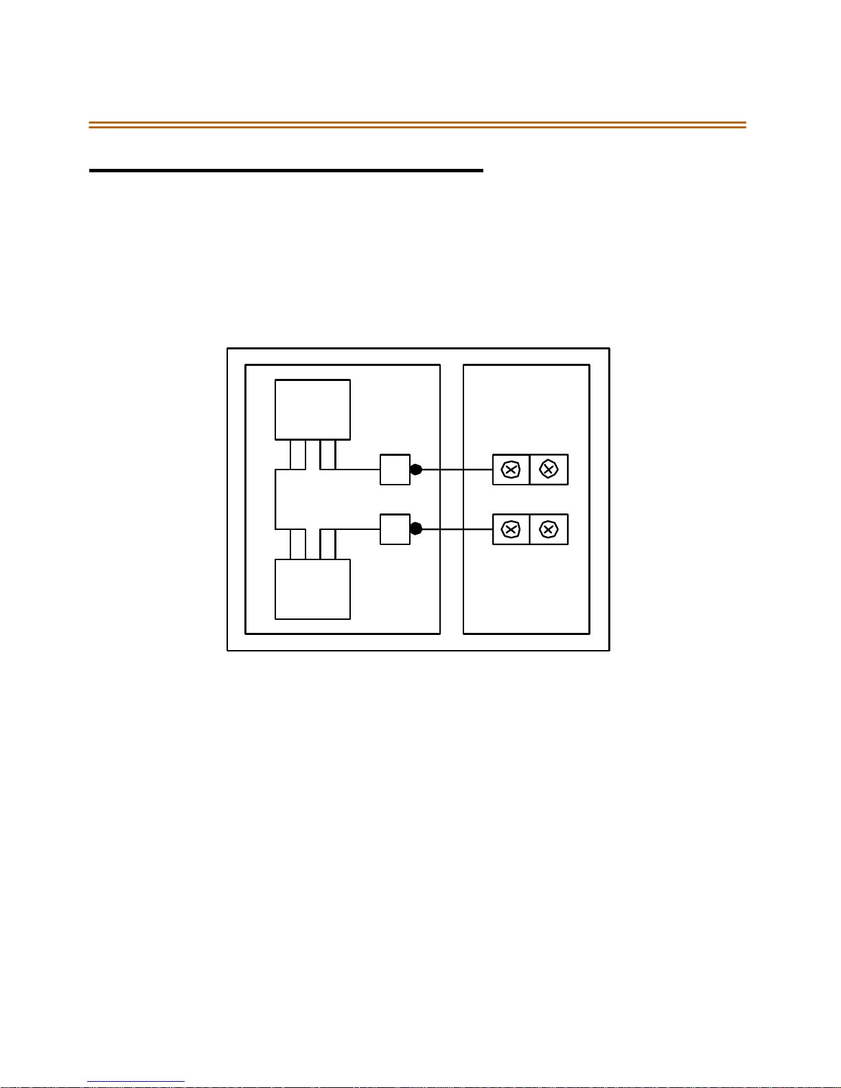
Syst em Wirin g 2-67
Sy stem Wir ing
Battery Back-Up Wiring Installation
The sys tem can be equipped to provide operation from external batteries
if loca l AC power fails . T he Back-U p ba tteries are co nnected to th e s tri p
connector on the front of the PSU as shown:
PSU
BATT
-+
+MARKER
+
-
+-
Fi gu re 2- 25 : Battery Ba ck-U p Wi ri ng
-MARKER
4PIN
CO N N
The external batteries must provide 24 VoltsDC. Thisis generally
accomplished by connecting two 12 volt batteries in a series
arrangement. Operation on batteries is controlled by th e PSU. This PSU
provides charging current to the batteries during normal AC power
operation at a max imum of about 1 amp.
During battery operation, thePSUs discontinue battery operation if the
AC power is reapplied or the battery voltage is too low to ma intain
proper system operation. If a low-battery cut-off occurs and a new
battery is installed, it is necessary to reset the Battery Back-Up circuit in
the PSU manually by momentarily depressing the white colored BATT.
RESTARTswitch located on the faceplateof the PSU.
Page 89
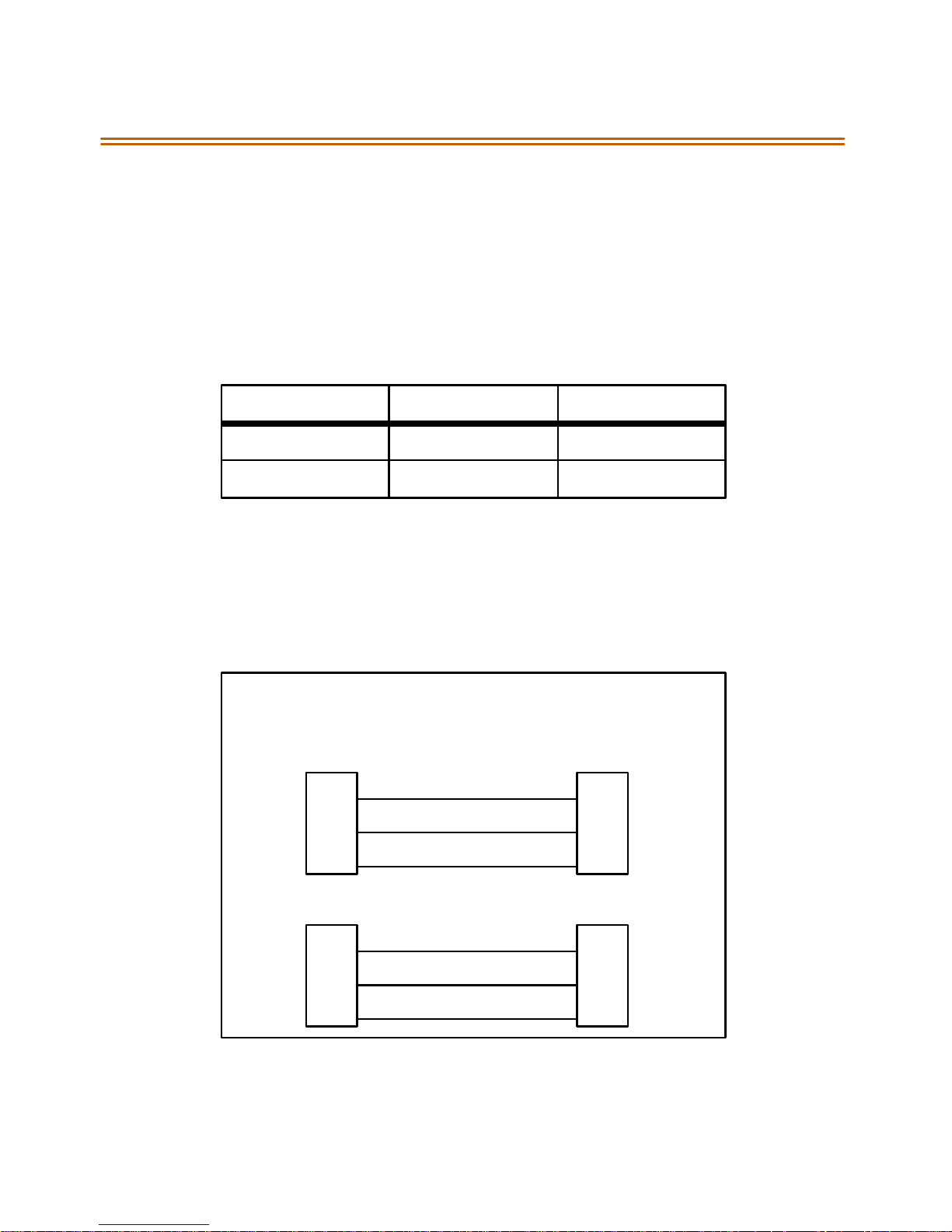
2-68 System Wiring
The l ength of t ime the system operates on t he batteries is depend ent on
several elements in cluding: battery charge state, condition o f the
batteries, capacity of the batteries, and th e size of the sys tem (number of
station ports).
The following chart gives the approximate back-up time for several
system sizes and different battery capacities in ampere-hours.
Table 2 -14: System Back-Up Duration
Ba ttery Capacity 36 Ports 60 Ports
20AH 4 Hour 1.75 Hour
40AH 8 Hour 3.5 Hour
MPB and SIU RS232C Port Wiring
The MPB has one standard RS232C port and the SIU has two standard
RS232C ports.The RS232Cports areconnected by 9-pin Dconnectors as
shown in Figure2-26. Note the configuration is 8 bits, no parity and 1 stop
bit.
MPB & SIU
RS232C
9PIN
2(TX)
3(RX)
5(GND) 5(GND)
9PIN 25PIN
2(TX)
3(RX)
5(GND) 5(GND)
2(RX)
3(TX)
3(RX)
2(TX)
TERMINAL
9PIN
F igu re 2 -26 : R S232 9-Pin Conne ctor Wiring
Page 90
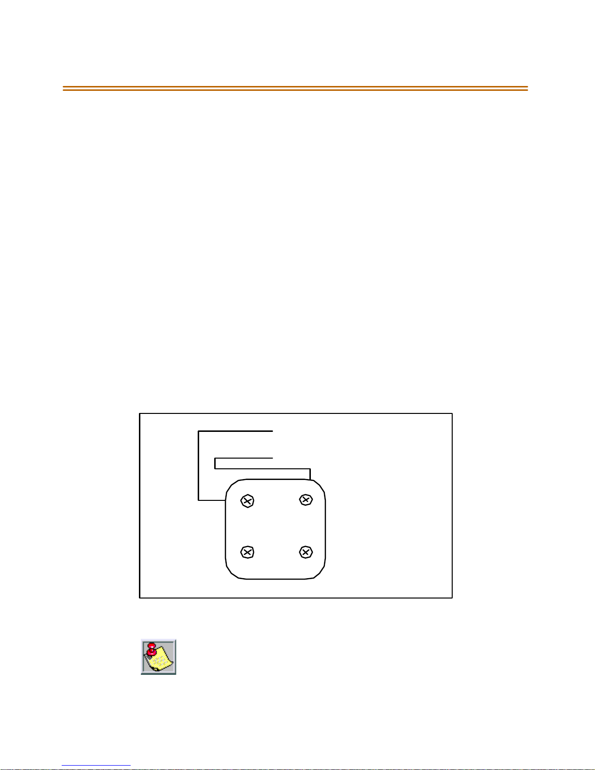
Syst em Wirin g 2-69
MISU Wiring
The MISB has connections for2 music sources, 2 External page zones and
4 relay contact controls. The MISB connections are made by the 25 pair
connector. The wiring connections for the 25-pair cable are identified in
Ta b l e 2 - 2 .
Station Wiring
Station interface boards (DTIB, ETIB, SLIB) includes a 25 pair connector for
station wiringto the ports on the board. The following provides details
onthe interconnection of eachtype of station interface board and the
station jack.
Digital Keyset and Terminal Wiring
Wiring from the DTIB to station jack requires one pair of wire. Digitized
voice, signaling , and power are sent ov er this pair.
Figure 2-27 givesdetailson connections ofstation jacksto the system and
Ta b l e 2 - 1 3 gives the configuration of the 25-pair station connector
arrangement and punchd own type block.
DT (GREEN)
DR (RED)
GYR
BK
Figure 2-27: Digital Station Jack Wiring
Only the first pair (Red, Green on jack) should be connected back to the
K SU. N o other pairs sho uld be connected b ack to the KSU.
Page 91
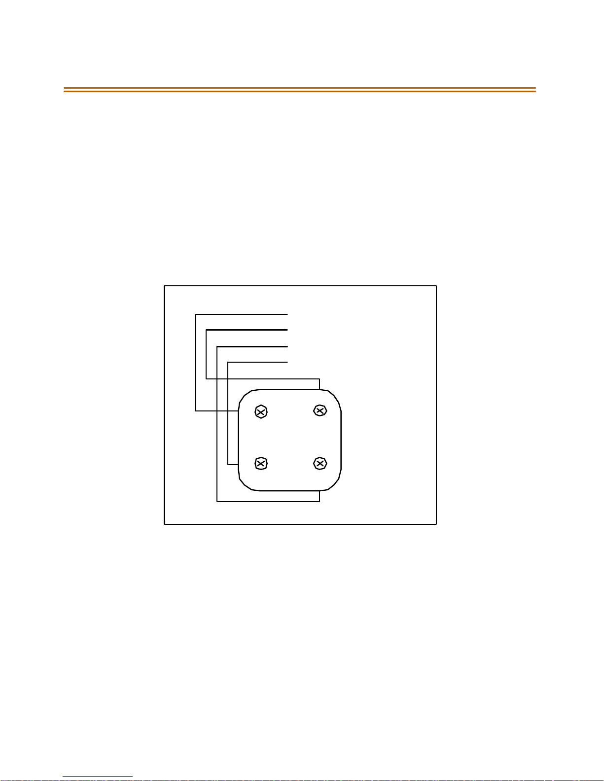
2-70 System Wiring
Electronic Keyset and Terminal Wiring
Wiringfrom the ETIB to station jack requires two pairs of wire. The first
pair provides theaudio or voice path,the secondis for signaling or data
path. The DATA pair is polarity sensitive, reversal does not ha rm the
keyset or system, but the port does not function properly when reversed.
Power i s deliv ered by a pplying DC voltage to t he center tap of the
coupling transformers of each of the 2 pairs.
Figure 2-22 givesdetailson connections ofstation jacksto the system and
Ta b l e 2 - 1 1 gives the configuration of the 25-pair station connector
arrangement and punchd own type block.
VT (GREEN)
VR ( RED )
DT (BLACK)
DR (YELLOW)
GYR
BK
Figure 2-28: Electronic Station Wiring
Page 92
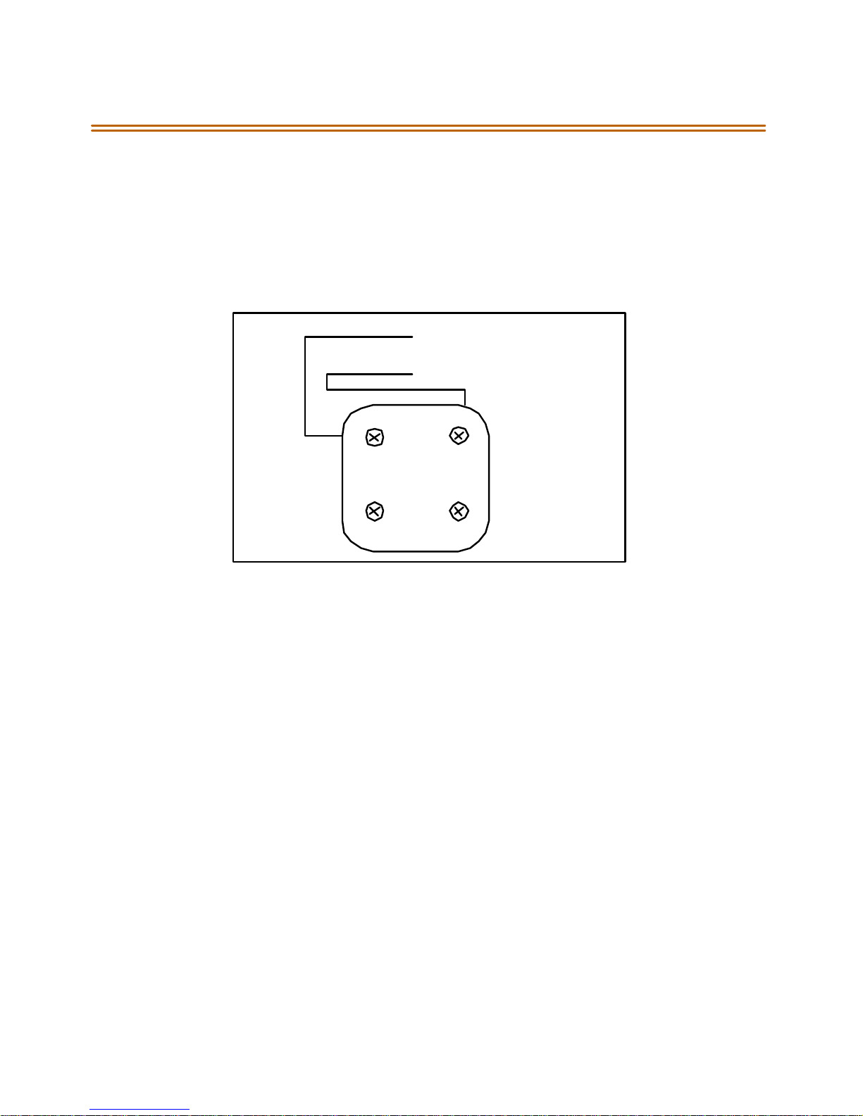
Syst em Wirin g 2-71
Single Line Telephone Wiring
The S LIB is wired to S LT dev ices with a sin gle pair of wire which provides
battery feed, voice and signaling to and fromthe SLT.Typical wiring to
the S LT ja ck is show n in Figure 2-29 and Ta b l e 2 - 1 2 giv es th e conf iguration
of the station connector arrangement when connected to a punchdown
type block.
VT
VR
G
YRB
Figure 2-29: Single Line Telephone Wiring
Page 93
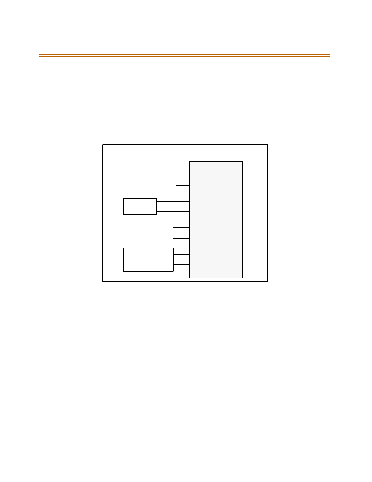
2-72 System Wiring
PowerFailure Transfer Wiring
ThePFTUiswiredfromthe25-pairconnectortotheMDF,cross
connected to the CO Line inputs from the telephone company, to the CO
Lineinputsofthesystem,andtoPowerFailureSLTs.Thebasic
connections are shown in Figure 2-30and the connector configuration is
given in Ta b l e 2 - 1 2 . Note that the SLT may also be connected to a SLIB as
showninthefigure.
MDF (P FTU)
CO L 1
CO L 2
LC OB
SLT
SLIB24
Subscriber
Figure2-30: PFTU Wiring
1
26
2
27
3
28
4
29
CO R 1- IN
CO T1 -I N
CO R 1- OUT
CO T1 -O UT
TEL1-R
TEL1-T
SLIB1-R
SLIB1-T
Page 94

Wall Moun ting the E le ctronic Telephone 2-73
Wall Mounting the Electronic Telephone
All connections to the Electronic Key Telephone are fully modular. To wall
mount t he Electroni c Key T eleph one, it i s necessary to have one Wa ll
Mount Kit and one standard-type jack assembly design ed f or normal wall
hanging applications.
1. Unplug theline cordfromthephone. Thisline cord is not be required
and should be retained as a maintenance replacement item.
2. Lift the plastic number retainer upward and expose the screw
un dernea th. R emove the s crew and th e handse t ta b. Repl ace it with
the handset tab fromthe WallMount Kit.
3. Be careful to position the tab so that the protrusion faces the
hookswitch. This allows the handset to remain secure when the
telephone is on the wall. Replace the screw and snap the number
retainerintoplace.
4. Subs titute the shor t modular cord fr om the Wal l Mount As se mbly
into the modular connector vacated by the line cord.
5. Alignthe wall mount baseplate withholes on the bottom of the
telephone. Snap in place.
6. Now ma tch the two ke y h ole sl ot s on the b asepl ate with t he l ugs on
the 630-Atypejack. Align themodularconnectorand slide telephone
into place. Refer toFigure 2-33.
Page 95

2-74 Wall M oun ting the Digital Telephone
Wall Mounting the Digital Telephone
To wall m ount the Digital Key Telephone, it is ne cess ary to use the Wall
Mount brack et and one standa rd-type jack a ssembly de sig ned for normal
wall hanging applications. Refer toFigure 2-33 and Figure 2-34.
1. Remove thehandsetfromthecradleandlocatetheplasticretainerin
the bottomof thehook-switch well area. Push the plastic retainer
sl owly upwar d un til it i s f ree. Locate the tab on th e p lasti c r etainer
and make sure the tab is toward you, then place it back into its holder.
Slide the plastic retainer all the way down into its channel. Part of the
retainer remains above its holder to hold the handset secure for the
wall mount configuration.
2. Turn the telephone over and unplug the line cord. If the line cord is
notplugged into the wall jack assembly, re-route the line cord thru
the access channelo n the top of the telephone. If the line cord is
plugged into the wall jack assembly, run the line cord through the
hole provided and plug into the connector on the back of the
telephone.
3. Line up the hooks on the top and bottom of the wall mount bracket
so they can engage with the slots cut into the bottom of the
telephone base. Insert the bottom hooks first. Slide the mounting
bracket slowly downwards until the top tabs slide into the top slots
andsnap in place.
4. Match the two key hole slots on the base plate with the lugs on the
630-A type jack. Align the mo dularconnector and slide the telephone
into place.
5. Place the handset onto the retainer. The telephone is now ready for
use. Refer to Figure 2- 34 for location of mounting information.
Page 96

Headset Installation 2-75
Headset Installation
The Triad 1/2/3 Electronic/Digital Key Telephones have been designed to
operate with industry standardelectret mic compatible modular headset
adapters an d operator headsets.
To modify a n El ectronic/Di gital Ke y Telep hone to supp ort an ex terna l
headset:
1. Plug the headset adapter cord into the vacant handset jack on the
Key Telephone base.
2. Plug the telephone handset cord into the headset adapter box where
indicated bythe headset manufacturer's instructions.
The Headset Operation must be enabled (refer to Station Programming).
The station then has thecapability to enable/disable headset modeby
dialing a code. When Headset mode is active at the station, th e ON/OFF
button controls the on-hook or off-hook status. Also, features such as
On-Hook Dialing and Handsfree Speakerphone operation become
inop erabl e.
Caller ID Interface Unit Installation
The Caller Identification InterfaceUnit receives the data fromthe
telephone company and sends the data, in ASCII RS-232C fo rmat to a
printer, telephone, com puter or DTE (Data Terminal Eq uipment) device.
Selecting the Cable
1. Select thecorrect RS-232 cable (P/N 9081-00) for the
Triad 1/2 MPB and SIU.
2. Connect one end of the cable on the desired KSU I/O port (1, 3, or 4).
3. Connect the other end to the OUT port on the Caller ID unit.
Page 97
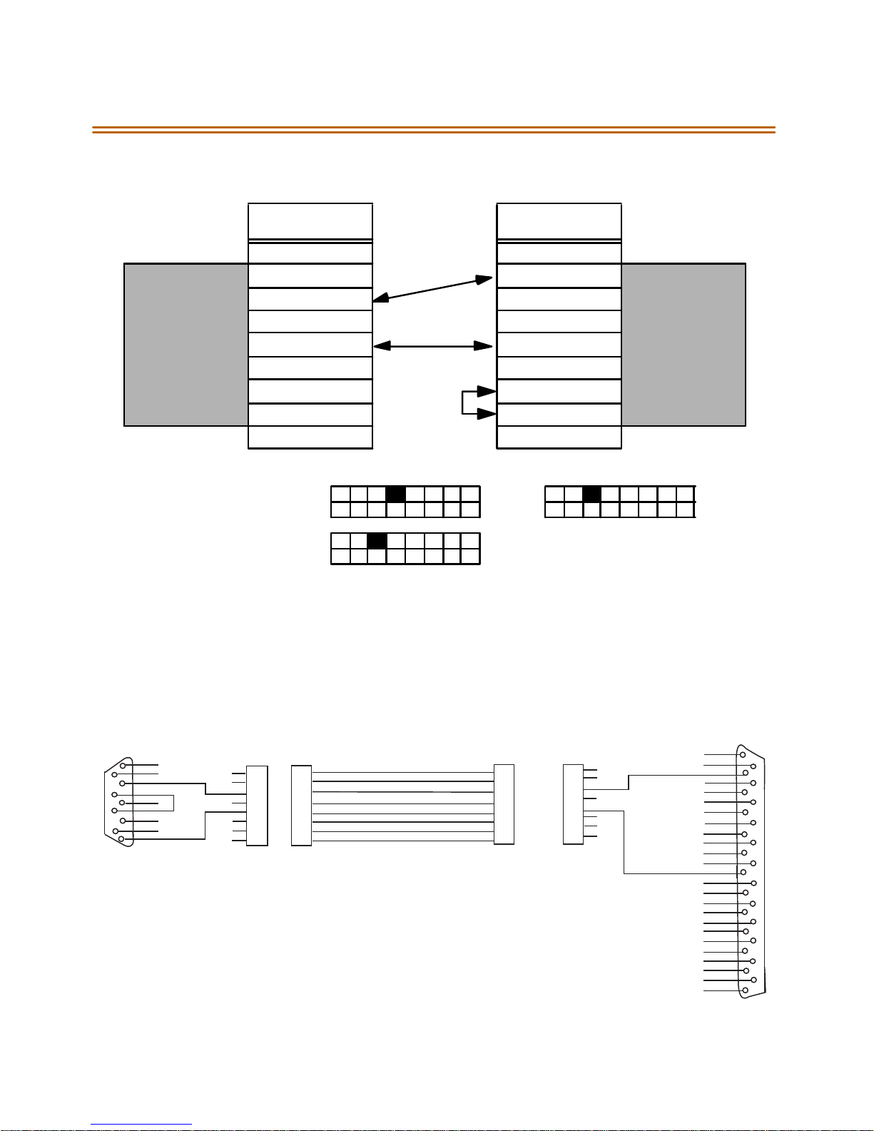
2-76 Caller ID Interface Unit Installation
Triad 1/2 MPB
and SIU
KSU9-Pin
Female Connec tion
1440/1480-00
9-Pin Male
11
22
33
44
KSU
55
CallerID Box
66
77
88
99
Figure 2-31:Caller ID Cable Connections
1480-00 Switch Settings
ON
OFF
1440-00 Switch Settings
ON
OFF
ICLID Cable Pin-Out Diagram
IC LID CA BLE PIN OUT DIAG R AM FO R 1428/4896/D VX I/D VX 3
DB9 to R J45 Adapter
P1
1
6
2
7
3
8
4
9
5
IC L ID E N D
X
X
YELLOW
X
X
X
RED
J1
8
X
7
X
6
5
X
4
3
X
2
X
1
X
RJ45
J3
8
7
6
5
4
3
2
1
RJ45
NOTES:
1. Cu ta ll oth er wir es in the adap ters s o that no ne of them short to e ach ot her o r
NOTE:
the con nectors.
2. Using two of the cut-off wires,strip the insul ation of t he cu t end back far
1. C ut all other w ires back in the adapters so that none of them short to each other or the connectors.
2. U sing tw o of the cut-off w ires, strip the insulation of the cut end back far enough (1/2 inch) to solder together.
enough (1/2inch) to solder together.
3. Insert the connector pins into Locations 7 and 8 of the D B9 connector (P1).
4. Insulate the solder joint with tape or heat shrink tubing.
3. Insert the connector pins into L ocations 7 and 8 of the DB9 connector (P1).
4. Insulate the sol der joint wi th tap e or h eat shri nk tubing.
RJ45/DB9/RS232
1480 CALLER ID CABLE
Digi-Key H2883-14-N D
S tra ig h t th ru C a b le
(D ig i-K e y R e v e rs e )
J4
8
7
6
5
4
3
2
1
RJ45
TO CP U
J2
8
7
6
5
4
3
2
1
RJ45
X
X
X
X
X
X
DB25 to R J45 Adapter
To RS -232 Bc D B25
YELLOW
RED
CONNECTOR DB25
P2
1
X
14
X
2
15
X
3
X
16
X
4
X
17
X
5
X
18
X
6
X
19
X
7
20
X
8
X
21
X
9
X
22
X
10
X
23
X
11
X
24
X
12
X
25
X
13
X
KSU END
Page 98
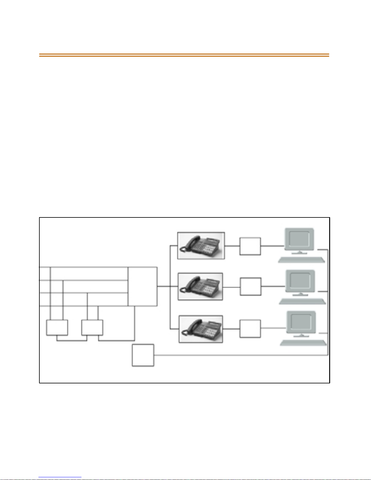
Caller ID In terface Unit In sta llation 2-77
Programming the KSU
I/O Por ts
1. Verify the programming for the I/O ports, press
✳✳
2. Select thedesired I/O port, Button 1, 3, 4 (MPB, SIU1, SIU2).
3. Dial [5] on the dial pad and press HOLD.
CO Lines
1. Verify the programming for the CO Lines, press
2. EnterCOlineRangefortheCallerIDUnitandpressHOLD.
3 . Pr es s B utt on 2 1 ( Pa ge C) .
4. Pres s Button 2 , Ri ng Del ay Timer.
5. Enter 04 (minimum). Press HOLD.
6. Reset the system and the CTI box.
STAR PL US
KSU
CO LINES
✳✳
CTI
Modul e
CTI
Modul e
3226, Flash 15.
3226, Flash 40.
LAN
LAN
IC LID
Interfa ce
Uni t
RS23 2
ICLID
Interface
Unit
Figure2-32: CTI System Configuration
RS232
SER VER
LA N
CTI
Modul e
LA N
LA N
Page 99
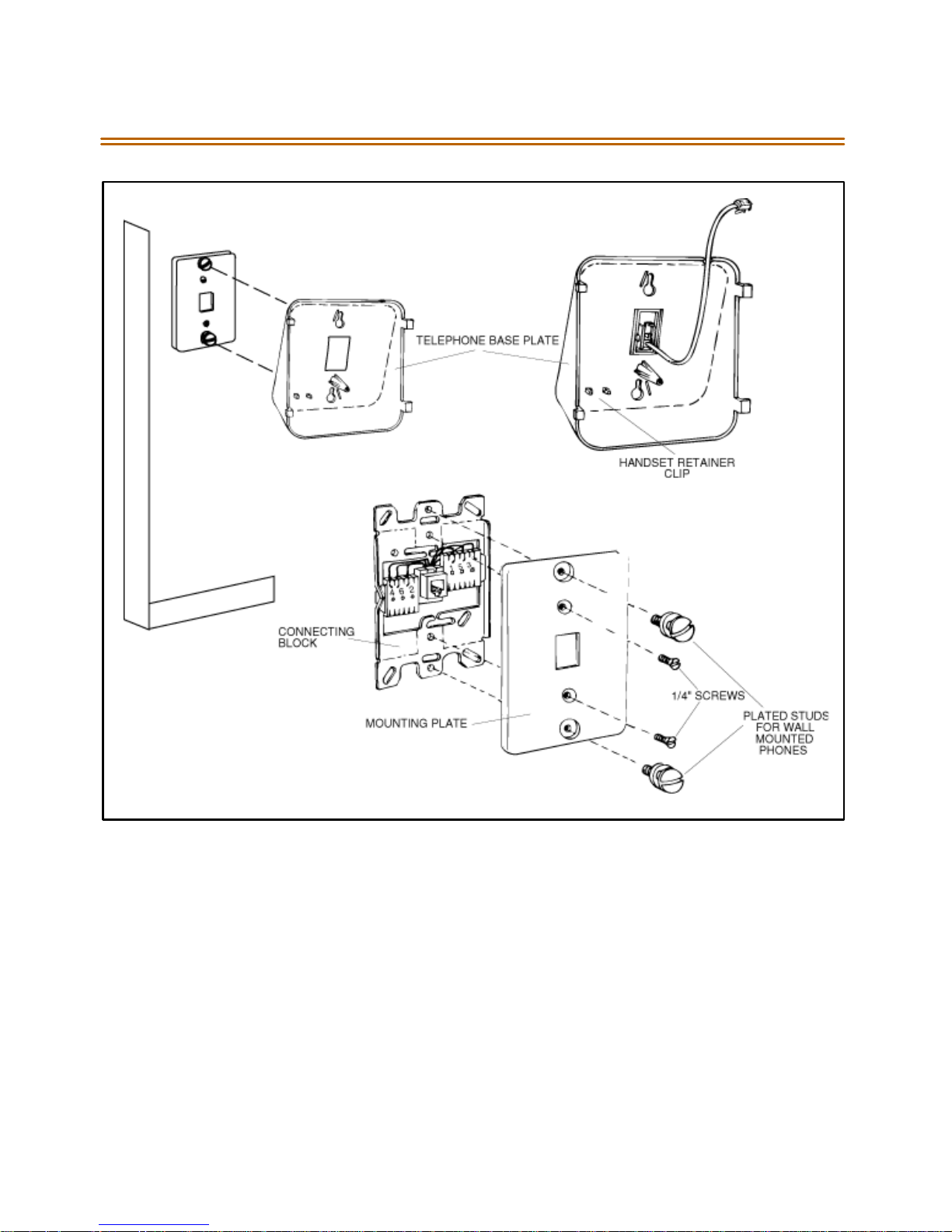
2-78 Caller ID Interface Unit Installation
Fi gu re 2- 33 : E lectron ic Key T elepho ne W all M ounting
Page 100
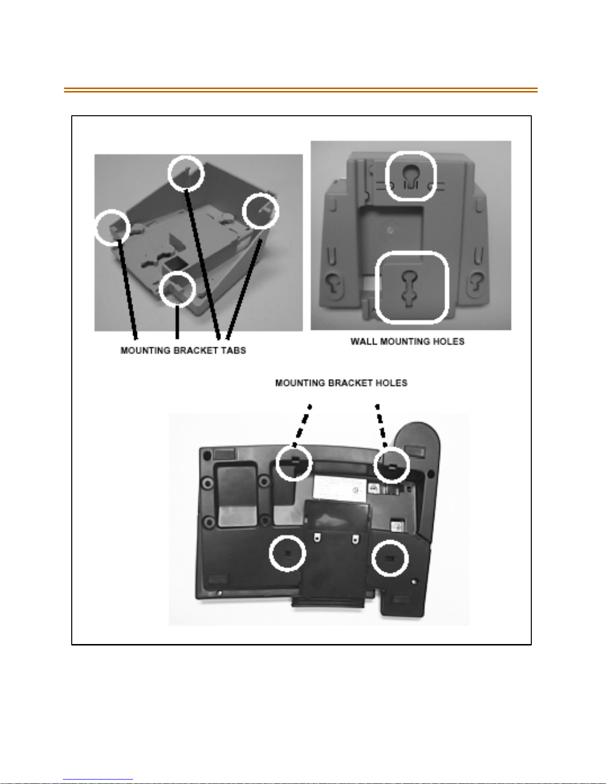
Caller ID In terface Unit In sta llation 2-79
Figure 2-34: Digital Key Telephone WallMounting
 Loading...