

Page 1

TM
STARPLU S
2800 -Series
Te lep hon es
User Guide
Page 2

I
Issu e Release Date Descript ion
1. 0 05 - 04 Ne w P ro d uc t R el e as e
1.1 06-04 Two-line wiring procedure added.
LIFE SUPPORT APPLICATIONS POLICY
VODAVI Techno logy, Inc. products are not authorized
for and should not be used within Life Support
applications. Life Support systems are equipment
intended to support or sustain life and whose failure to
perform when properly used in accordance with
instructions provided can be re asonably expected to
result in significant personal inj ur y or death.
VODAVI Technology, Inc. warra nt y is limited to
replacement of defective components and does not
cover injury to persons or prop erty or other
consequential damages
“WARNING: Handling the cord on this product will expose you to lead, a chemical
known to the State of C alifornia to cause [cancer, an d] birth d efects o r other
rep roductive harm. Wash hands after handling.”
Copyright © 2000 VODAVI Technology, Inc.
All Rights Reserved
This material is copyri ghted by VODAVI Technology, Inc. Any
unauthori zed reproductions, use or disclosure of this material, or
any part thereof, is strictly prohibited and is a violation of the
Copyright Laws of the United States (17 U.S.C. Section 101 et. seq.).
VODAVI reserves the right to make changes in specifications at any
time and without notice. The information furnished by VODAVI in
this material is believed to b e accurate and reliable, but is not
warranted to be true in all cases.
STARPLU S™ is a registered trademark of VODAVI Technology, Inc.
set/2004
PR IN TE D IN TH AILAN D
Page 3

Important Safety Inst ructions
When using your telephone equipment, basic safety precautions
(including the following) should always be followed to reduce the risk of
fire, electric shock, and injury to persons.
» Read and understand all instructions.
» Follow all warnings and instructions marked on the telephone.
» Do not use liquid cleaners or aerosol cleaners on the telephone; use a
damp cloth for cleaning.
» Do not operate the telephone around water (i.e., near a bath tub,
wash bowl, kitchen sink, laundry tub, swimming pool, or in a wet
basement).
» Do not place this telephone on an unstable cart, stand, or table. The
telephone may fall causing serious damage to the telephone.
» Slots and openings on the bottom of the telephone are provided for
ventilation to protect it from overheating. These openings must not
be blocked or covered. The openings should never be blocked by
placing the telephone on the bed, sofa, rug, or other similar surface.
This tel ephone should never be placed near or over a radiator or heat
register. This telephone should not be placed in a built-in i nstallation
unless proper ventilation is provided.
» Never push any obje cts into this tel ephone through slots a s they m ay
touch dangerous voltage points or short-out parts that could result
in a fire or electric shock. Never pour any liquids on the telephone.
» To reduce the risk of electric shock, do not disassemble this
telephone. Take the telephone to a qualified serviceman when
service or rep air work is needed. Opening or removing covers may
expose you to dangerous voltage or other risks. Incorrect reassembly
can cause electric shock when the app liance is subsequently used.
» Avoid using a telephone (other than a cordless type) during an
electri cal storm. There may be a remote risk of electric shoc k from
lightning.
» Do not use the telephone to report a gas leak in the vicinity of the
leak.
--- SAVE THESE INSTRUCTIONS ---
Page 4

Page 5
Product Information 1
Product Informa tion
All three 2800 models are FCC r egistered, and both hearing aid and
American Disability Act (ADA) compli ant.
Stand ard Fea tur es incl ude handset volume button, data jack, message
wait ing li ght, redial button, flash butto n, desk mount, and ringer control
switch. The STARPLUS 2800 telephones also come with a 5-year standard
manufacturer ’s warranty.
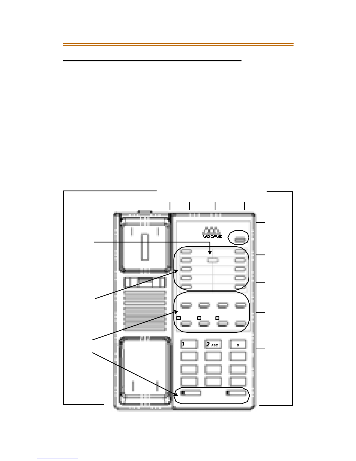
Two-line Models also have programming capabilities and separate line-
control functions. The following diagram shows whe re to locate the
feature buttons and switches used to operate the 2800-series telephones.
MODEL 2803
“Hidden”
Programming
Button
Programmable
Memory
Buttons
Fixe d
Feature
Buttons
Tone/P uls e
LN1
Jack
LN2
Switch
Jack
TM
VOD AVI
PA USE RE D I AL FL A SH VO LU M E
CONF LN 1 LN 2 HOLD
12ABC DEF
456
FLASH
Switch
ME SSAG E
3
MNOJKLGHI
Data
Jack
B / Z
Ringer
Line1
Ringer
Line2
Ringer
Spe ake r
Vo l u m e
PQRS TUV WXYZ
789
OPER
*
MUTE SPKR
0#
Page 6
2 Product Information
2800-Series Features
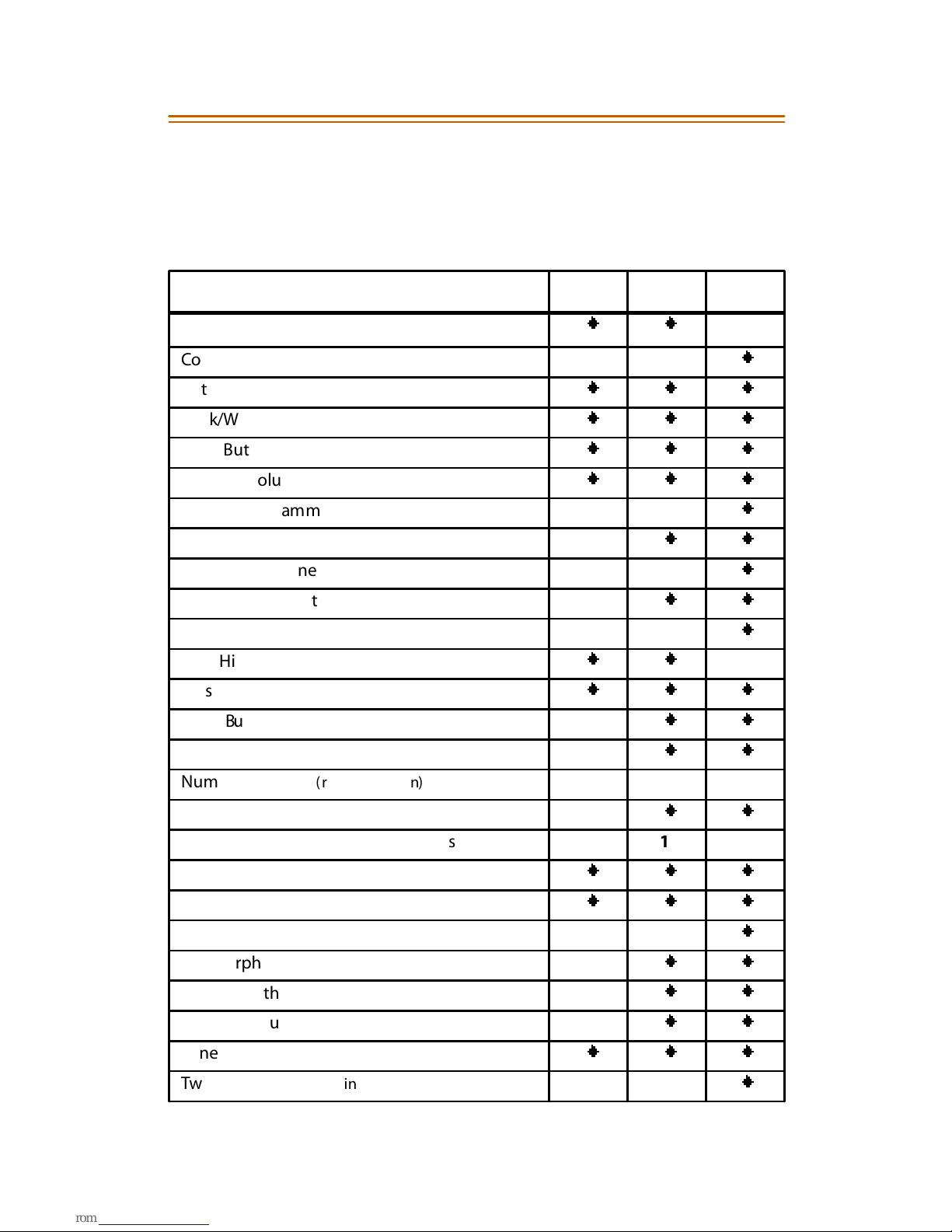
Use thi s feature/comparison chart t o i dentify t he functions that pertain to
yo ur telep h one. (Model number located on bottom of telephone base.)
Feature
A-Lead Connection
Conf erence Button
Data Jack
Desk/Wall Mountable*
Flash Button
Handset Volume
Hidden Programming Button (h ot el/m ot el o nly )
Hold Button
Hold for Each Line
Line In Use Indicator
Low/High Ringer
Low/High/Off Ringe r
Message Wait L amp
Mute Button
Mute with LED
2801 2802 2803
NN
N
NNN
NNN
NNN
NNN
N
NN
N
NN
N
NN
NNN
NN
NN
Numb er Me mory ( redial function) 111
Pause Function
Programm able Me mory Dia l Buttons 10 10
Programmable Flash Time
Redial Button
Ring Indicator
Speakerphone
Sp eak er with LED
Sp eak er Volume Control
Tone/Pulse Selection
Two Lines ( distinctive ring tones)
* Wall Mount Kit, optional
NN
NNN
NNN
N
NN
NN
NN
NNN
N
Page 7
Installation 3
Telephone Specifications
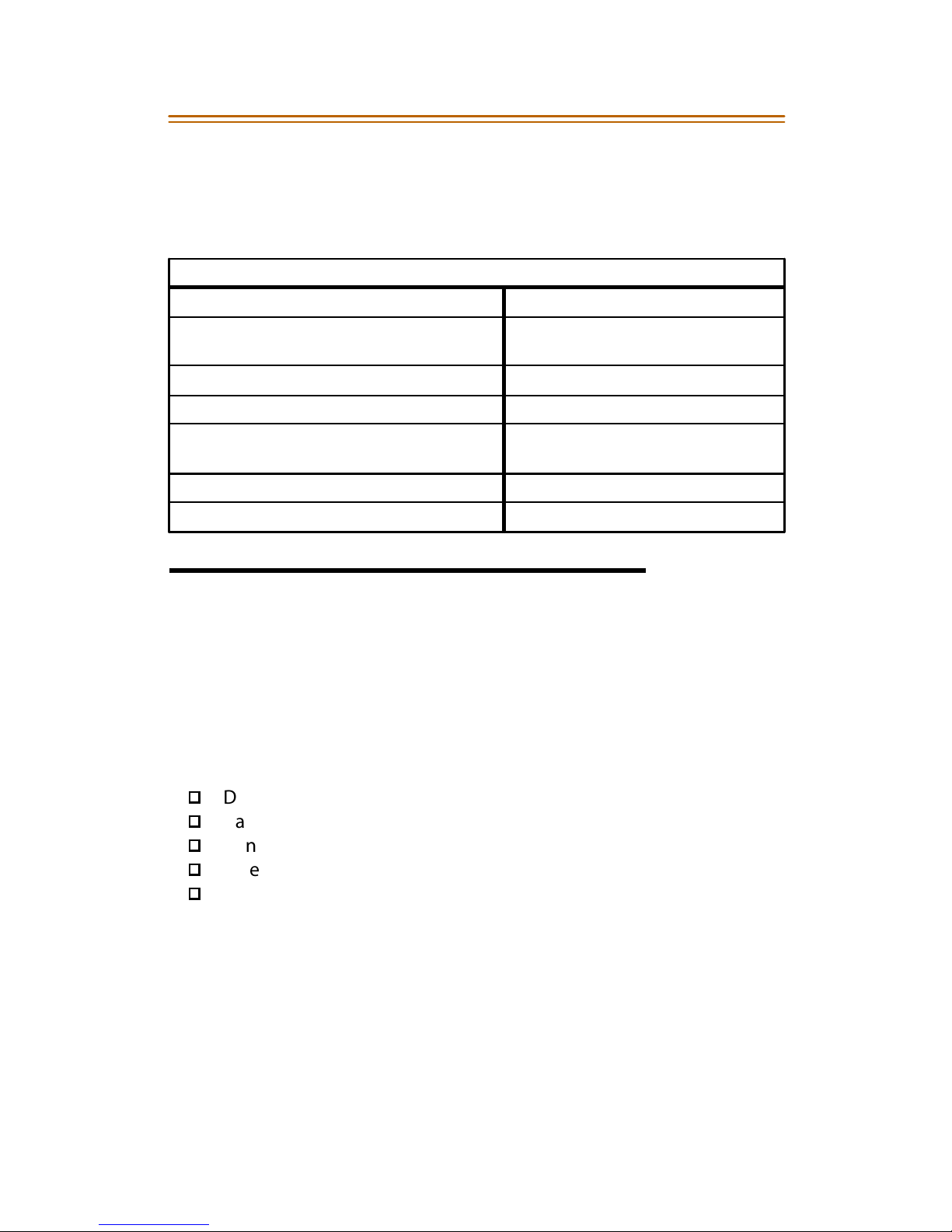
The following product list show s the dist inctive characterist ics of the
2800-model telephones.
Product Detail
Cabling R equirement -- 1 pair Minimum Message Waiting -- 70-90 VDC
FCC Specifications -- Part 15, Subpart J,
Cl a ss A , P ar t 68
Flas h Timing -- 100, 300, 600ms ( Programmable) R egistered Connector -- USOC RJ 11
Footprint -- 8.75" x 6.25" Ringer Equivalence -- B/Z Switchable
Handset -- Standard K Style,
Hearing Aid Compatible
Handset Cord Length -- 9 ft Signaling -- Standard 12 tone DTMF
Line Cord Length -- 12 ft Weight -- 2.5 lbs
Operating Voltage -- 12 to 56 VDC
Non Polarity
Safety Standard -- NTRL/C
Installation
Parts List
The 2800-Series Telephones come with all the parts you will need to
operate your telephone. Verify that the items listed below have been
included prior to startin g the installati on process.
Vodavi 2800-Series Telephone
Desk-Mount Telephone Base
Han dset
Handset Cord - 9 ft
Line Cord - 12 ft
User Guide
Desk Telephone
To i nst al l y our new tele phon e:
1. Plug one end of the handset cord into the handset, and plug the
other end into the handset jack on the side of th e telephone.
2. Set the B/Z Ringer switch.
3. Plug one end of the line cord into the LINE1 jack, and plug the other
end into the wall jack.
On Two-L ine Mo del s --- Either line jack may be used, LINE1 or LINE2.
Page 8
4Installation
Wa l l M ou nt (optional)
If desired, any 2800 telephone can be converted to a w all mount unit. For
easier mounting, the optional Wall Mount kit comes with a 9-in. line cor d.
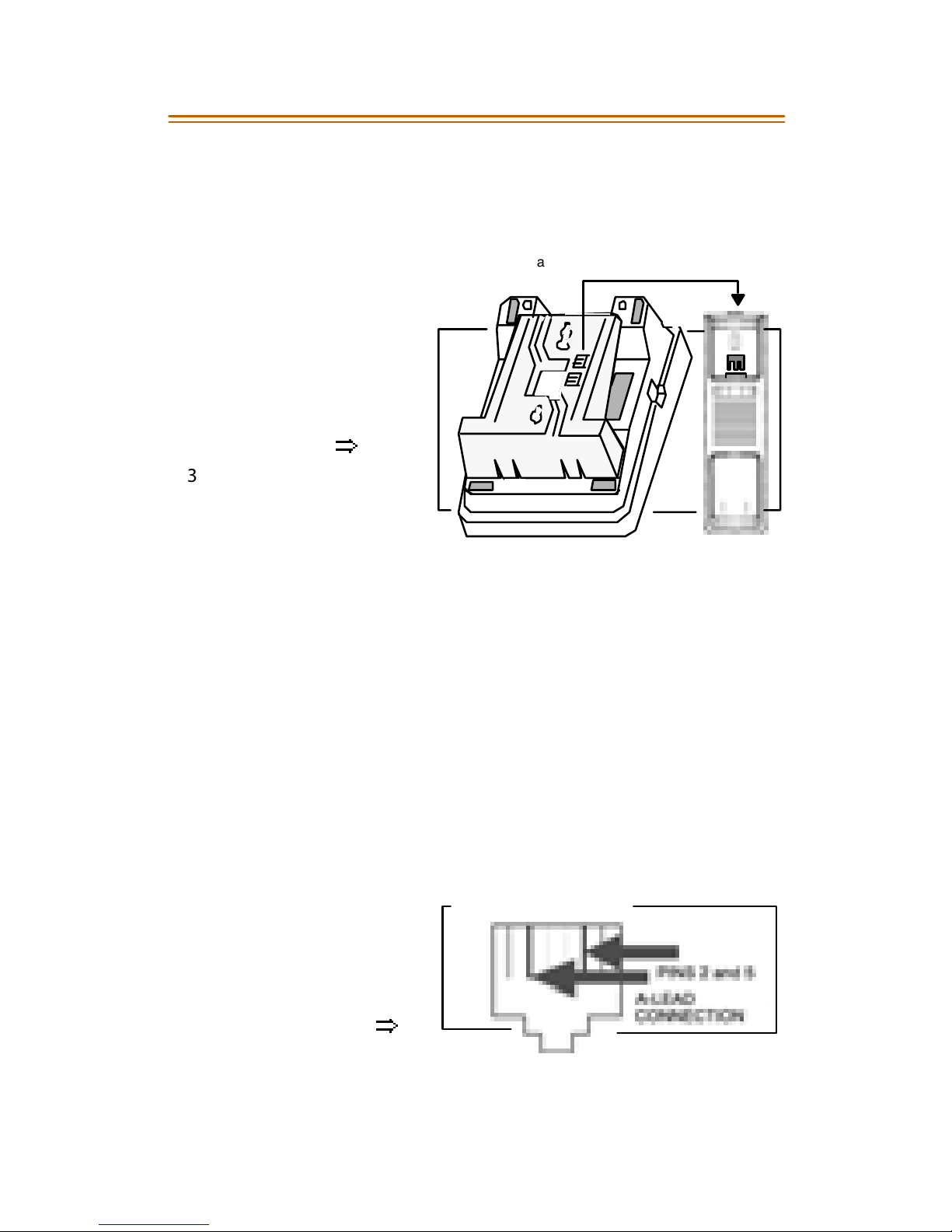
To install wall mount:
Wall Mount
Ta b
Handset Cradle
1. Detach one (1) of two
plastic tabs located
on the Wall Mount .
↓↓
2. Remove the handset
TOP
from the cradle; insert
the t ab in to the sl ot
bel ow the h oo kswit ch
as shown …
⇒
3. Unplug existing line
cord from teleph on e
and wall jack.
4. Run the line cord
pr ovid ed t hr ou gh th e
Ta b will hold handset securely when
telephone is used as wall mount.
rectangular opening
of the Wall Mount and plug it into the line jack of the telephone.
5. Insert the “bottom” Wall Mount prongs into the slots on th e
“bot tom” of th e telephone base.
6. Gently press down on the Wall Mount until the prongs on the “top”
snap into the slots on the “top” of the telephone base.
7. Plug the other end of the li ne cord into the wall jac k.
8. Match the two “keyhole” slots on the Wall Mount with the lugs on
the 630-A type jack, and slide the telephone into place.
9. Return the han dset to the cradle; the telephone i s ready to use.
Connections & Wiring
A-Lead
An A-Lead Connection is
available on the 2801 & 28 02
models. The connection is
mad e via the LINE1 jack
outer pairs as shown …
⇒
PI NS 1 2 3 4 5 6
Page 9
Installation 5
LN
Data J ack
The data jack on the 2803 model is wired to LINE2 from the factory. To
change from LINE2 to LINE1, perform these steps:
1. Remove the 4 scr ews on the bott om of the tel ephone, and separate
the bottom h ousing from the upper housing.
2. Remove wire/plug from connector CN21 (L2) & place on CN11 (L1).
3. Reassemble t he telephone, m aki ng sure all w ires are plugged in.
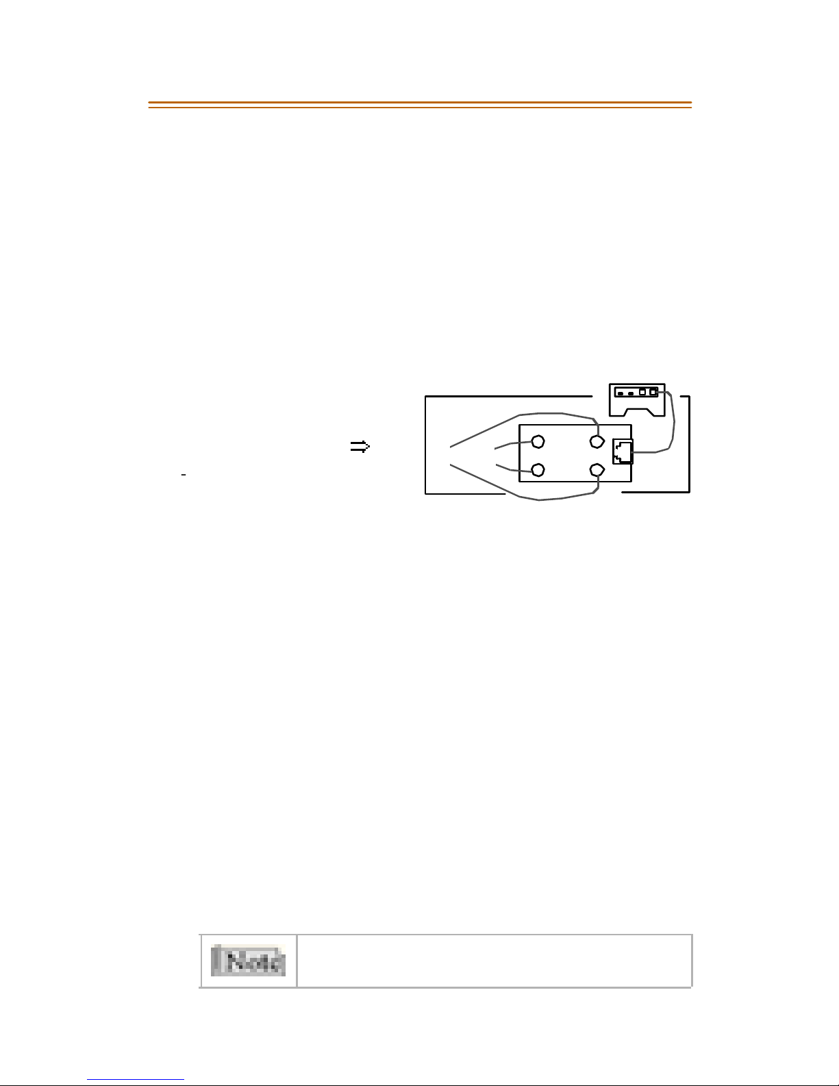
Two-Line Connections
When connecting two phone lines to the 2803-model telephone, observe
the foll owin g recommendations.
» If you utilize the LN1 connector
to bring in Lines 1 and 2 in your
installation, use a 4 -pin (2 pair)
line cord as shown …
⇒
-- green & red wires for Line1
-- ye llo w & bl ack wires for Line2
RBK
Line 1Li ne 2
GY
28 03
1
In this install atio n method, no connect ion should be made to the LN2
conn ect or. (Failure to do so could result in a conference situ ation
between Li nes 1 and 2.)
» If you utiliz e both the LN1 and LN2 connectors in your inst allati on,
make sure that a 2-pin ( 1 pair) line cord is used.
Connecting a Modem to Your Telephone
This feature allows data transmission via the DATA jack on the telephone
using a computer equipped with the modem function, or a modem
connected by hard-wiring. Single-line models (2801 and 2802) use LINE1
for modem transmissions, two-line models (2803) use LINE2.
To connect a modem to your telephone:
1. Locate th e DATA jack on the ri ght-side of the t elephone, and th e
teleph on e jack connec ti on on the modem .
2. Connect a line cord to the jack on the modem; plug the other end
of the cord into the DATA jack on the telephone (RJ11 connection).
The modem is now connected through your telephone on LINE1 or
LINE2. Calls c an be or iginated and passed on to the modem .
Consult the instru ctions provided wit h your m odem.
Two-Line Models (2803) --- LINE2 can be used for inco ming &
outgoing calls when modem is not in use.
Page 10
6Installation
Setting the Volume
Ringer Vol um e Switch
This swi tch is l ocated on the right si de of the t elephone. You may set the
ringer volume swit ch to HI, LO, or OFF. When the switch is m oved to the
OFF position you will not hear ri nging from th at t elephone. However , an
extensi on telephone using th e same line will ring during an incoming call .
Tw o-Li ne Mod els - -- The 2803 telephone has two volume switches, one for
each line. This hospit ality model does not have an OFF posi tion, the
volume can only be changed to HI or LO.
B/Z -Type Ringer
The B/Z Ringer switch is located on the right side of the telephone near
the Ringer Volume switches. This switch should be set to “B” for residential
use, and “Z” fo r business/hospit alit y applications.
The MSG li ght a nd the Line In Use (LIU ) LEDs will n ot o per ate w hen set
in the “B” ringer mode.
Handset Volume
Each 2800-model telephone has a volume button t hat allows you to
increase or decrease the handset volume while on an active call. The
settings are: Normal and High.
Speakerphone Volume Switch
Speakerphone models (280 2 & 2803) are equipped with a sliding volume
switch to adjust the speakerphone volume. Slide the switch toward you
for lower volume, or away from you for higher volume.
Acc essin g th e Dire cto ry Ca rd
Frequently dialed numbers may be recorded on the Directory Card. For
models with speed dial memory, the card can be used to record the
telephone numbers stored in One-Touch speed dial memory.
To remov e t he ca rd:
1. Insert a paper clip in the hole at the top of the vinyl overlay
covering the card.
2. Lift the overlay and remove the card.
Page 11

Ope ratio n 7
Operation
Two-Line Models - If you have a 2803-model telephone, press the
appropriate LINE button before lifting the handset, or press the SPKR
button. The -green- LIU indicator on your telephone will the n illuminate,
as well as any extension telephones with LIU indicators. Each LINE button
has two i ndicator s:
» The -green- indic ator illuminates whe n the line is in use.
» The -red- indicator i llu minates when the lin e is plac ed on Hold, or t o
show an incoming call .
Single-Line Models - The HOLD button serves as the LIU indicator. The
LED will be -green- when you lift the handset, or press the SPKR button.
The LED will be -red- when a call is waiting to be answered.
Message Waiting Indicator
If you h ave a telephone messaging service, the MSG lamp wil l il lumin ate
to indicate a message is waiting. Information regarding availability and
operati on may be obtained thr ough your service.
Two-Line Models (2803) --- The MSG lamp wi ll illuminate on LINE1 only.
Flash
The Flash feature will allow you to access features available through
Custom Calling servi ces. Flashes may be stored in t he t elephone m emo ry.
Press th e FLASH button while on a call to generate a flash.
Last Number Redial
The last number dialed from the telephone will be stored when you hang
up. LNR mem ory can store a t elephone number up to 32-digit s in length.
To access the last numbe r dialed f rom your telephone ( 280 2/2 803):
1. Lift the handset, or press the SPKR button.
2. Press the REDIAL button, t he n umber wi ll autom atically dial out.
To dial the last number called f rom your telephone ( 280 3):
1. Press a LINE button.
2. Lift the handset, or press the SPKR button.
3. Press the REDIAL button, t he n umber wi ll autom atically dial out.
Page 12

8Operation
Changing from Handset to Speakerphone (2802 & 2803)
While using the handset:
1. Press the SPKR button.
2. Hang up the han dset, the SPKR indicator wi ll l ight.
While using the speakerphone:
Lift t he handset, the SPKR i ndicator will turn off.
Mu te (2802 & 2803 models)
To mute your voice while on a call:
1. Press the MU TE button, the -red- Mute indicato r wi ll illumi nate.
2. Press any key to resume conversation; Mute indicator wi ll turn off.
The Mute feature will automatically disengage when changing
from handset to speaker.
Hold (2802 model)
To place a call on hold:
1. Press the HOLD button, the LIU indicato r wi ll illumi nate - red-.
2. Ha ng-u p the ha ndset.
To retrieve a call from hold:
» If you have already hung-up the handset, lift the handset or press
the SPKR button on your telephone.
» If the handset is not hung-up, press the HOLD button to resume
conversation. The LIU indicator will illuminate -green-.
Hold (2803 model)
To place a call on hold:
Press th e H OLD butt on, the Line indicator will change to -red- for
that line.
To retrieve a call from hold:
Lift the h andset , o r press the SPK R button on yo ur telephone or an
extension telephone.
If t he call w as placed on HOLD wit hout hanging up the handset:
press the hookswitch to recover the call and resume your
conversation.
Page 13
Ope ratio n 9
Me mory Di al ing (2802 and 2803 models)
Ten frequently dialed telephone numbers can be stored in the telephone
memory. A number stored in memory c an be accessed with one-touch of
a Speed Dial button.
Memory Retention Time
Typically, t he numbers you choo se to sto re will remai n in m emo ry until
they are overwritten with a new number.
Model 2802 - -- If the telephone is “unplugged” from an active telephone
line, stored numbers w ill only stay in mem ory for 24 hours.
Model 2803 -- - The t wo-line model co ntains a l ithiu m battery that al lows
sto red numbers to be retained indefi nitely, or until changed.
To store a telephone number in memory:
1. Lift the handset, or press the SPKR button.
2. Then press the STORE button.
» For 2803 model … remove overlay to access STORE button.
3. Dial the number you want to store into memory.
(The choices are: 0 -9, *, #, PAUSE, or FLASH).
» For 2802 model … use REDIAL button for Pause function.
4. Press one of the ten Speed Dial buttons where you want to store
that teleph one number.
To enter “multiple” memory locations … press the hookswitch and
repeat Steps 2 through 4 for each number you want to store.
5. When fi ni shed, han g up the handset.
A “dial tone” will be heard while performing this operation.
To dial a telephone number stored in memory:
1. Lift the handset, or press the SPKR button.
2. Press the Speed Dial button where you stored the number.
Page 14
10 Operat ion
Conferencing (2803 model)
To initiate a c onference call:
1. Press a LINE butt on and dial th e fir st party’s telephone number.
2. When the first party answers, advise them that a conference call is
being establi shed and press the HOLD button.
The -green- Line indicator will extinguish, and the Hold indicator
will i llu minate -red- for that li ne.
3. Press th e o ther LINE butto n; di al seco nd par ty’s telep hone number.
4. When the second party answers, advise them of the confer ence call
and then press the CONF button.
» The fi rst call w ill be released from Hold and you will be able to
converse wi th both parti es at th e same time.
» The -red- Conference LED illuminates steady, and the -green-
LEDs for both li nes w ill remain li t.
If the se con d part y’s li ne i s b us y:
Press the fir st LINE butt on to return to the fi rst party.
The first part y is released from Hold; resume your conversation.
To terminate a conference call:
1. Hang up the han dset, or press t he SPKR button if in SPKR mode.
Both Line indic ators wil l extinguish .
2. Press th e CONF button in order to terminate thi s funct ion.
If the CONF button is not presse d after you hang up, both
lines will be accessed simultaneously the next time the
telephone is used.
To talk with only one party from the conference:
1. Press the LINE button for the desired conversation.
The -red- Conference LED will extinguish; Line LED will light steady
for selected line; the other line will be disconnected.
2. Resume the conversation.
To end a conference, placing both lines on Hold:
Press the HOLD button.
The -red- Conference LED will extinguish, and the LIU LEDs will light
steady -red-. Both first and second parties are placed on Hold.
Page 15
Programming 11
Programming
The Tone/Pulse & Flash Timing settings may be changed by moving their
respective “recessed” switches located at the top of a 2800-telephone.
Tone/Pulse
Move the switch to the desired position: “T” o r “P”
Flash Timing
Slide the switch to one of these settings: 100, 300, or 600 ms
Troubleshooting Guide
If this telephone does not work properly, try the following suggestions.
Cond it ion Sugg est ion
No Dial Tone » Check all cables to make sure that all connections
are secure and not damaged.
» Check the hookswitch. Does it fully extend when the
handset is lifted from the cradle?
» Check to make sure the tel ephone i s not on Hold.
» Unplug the telephone and connec t it to another
modular jack. If it still does not work, and other
telephones in your home are working, the problem
is with this telephone.
Te le phone does not
dial out
Te le phone does not
ring
Incoming and
out g o in g v oi ce
volume is low
Check the dial m ode in the prog ramming area .
Is it set to tone, which may not be compatible with your
local dialing service?
Are you using too many telephones on one line?
The total REN of al l telephones on the same line should
not be greater than the maximum REN for your calling
area . (Refer to the FCC Registration Information.)
Are other telephones off hook at the same time?
If so, this is a normal condi tion. The volume le vel drops
when additional telephones are used at the same ti me.
Spe ake rphone
does not work
Difficulty storing
numbe rs in me mory
If the other person cannot hear you, make sure the
MUTE li ght i s off.
Make sure you are pressing the correct sequence of
buttons for s toring me mory.
Page 16

Page 17

REGULATORY INFORMATI ON
FCC Part 68 Compliance
These tel eph ones ar e hearin g-aid comp ati bl e
and comply with Part 68 of the Federal
Commu nications Commission (FCC) rules. On
the bottom of the telephone is a label that
cont ains, amon g other info rmatio n, th e FC C
registration number and Ringer Equivalence
Number (REN) for the telephone. If
requested, this information must be
provided to the telephone company.
Installation
The modular telephone ou tlet or jack to
which the telephone must be connected is a
Un iver sal Servic e Or der Co de ( USOC) R J1 1C
or RJ11W. For modem interface purposes on
two-line models, the connection may be
made using a USOC RJ14 type jack. The
telephones are registered to operate in
Central Office (CO), private branch exchange
(PABX), key system and Centrex applications.
The telephones cannot be used on telep hone
company-provided coin service. Connection
to Party Line Service is subject to state tariffs.
Ring er E quiv ale nce Num ber
The REN is used to determine the quantity of
devices which may be connected to the
telephone line. Excessive RENs on the
telephone line may result in the devices not
ringing in response to an incoming call. In
most, but not all, areas the sum of the RENs
should not exceed 5. To be certain of the
nu mb er o f d evices th at may b e co nn ected t o
the line, as determined by the total RENs,
contact the telephone company to
determine maximum REN for calling area.
Incidence of Harm
If th is equipment causes harm to the
t e lep ho ne n etw o rk th e te l ep ho ne c om pa n y
will notify you in advance that temporary
discont inuance of service may b e required. If
advance notice isn't practical, the telephone
company will notify you as soon as possible.
Also, you will be advised of your right to file a
complaint with the FCC if you believe it is
necessar y.
Telep hone Com pany Rights
The telephone company may make
modifications in its communications facilities,
equipment, ope rations, or procedures that
could affect the operation of the equipment.
If th is happens, the telephone company will
provide advance n otice in order for you to
make the necessary changes to maintain
un i nt err upt ed ser vic e.
FCC Part 15 Compliance
These telephones have been tested and
found to comply with the limits for a Class B
dig ital dev i ce, p ur sua n t to P art 15 of th e FCC
Rules. These limits are designed to pro vide
reasonable protection against harmf ul
interference in a residential installation.
This equ ipment may generate, use, an d/or
radiate radio frequency, and if not installed
and used in accordance with the instructions,
may cause some interference to radio
communications. However, there is no
guarantee that interference will not occur in
a particular installation. If equipment does
cause interference to radio or television
reception, which can be determined by
turning equipment on and off, try to correct
the interference by one or more of the
following meas ures:
Reorient or relocate receiving antenna.
Increase the separation between the
equipment an d the receiver.
Connect equipment to an outlet on a
circuit different from that to which the
receiver is connected.
Consult the dealer or an experienced
radio/TV technician for as sistance.
Changes or modifications n ot ex p ressly
approved can void the user's authority
to o perate the equipment.
UL Compliance
These telep hones comply with UL 1459,
second edition requirements and bear the
NRTL/C label denoting co mpliance. For your
own protection, observe the following:
Never install tele phone wiring during a
lightning storm.
Never install telephone jacks in wet
locations unless the jack is specifically
designed for u se in wet locations.
Never touch uninsulated telephone
wires or terminals u nless th e telephone
line has been disconnected at the
network interface.
Use every caution when installing or
modifying telephone lines.
WARRANTY INFORMATION
If you experience any trouble with the
telephone, please contact your servicing
agent/distributor for repair and/or warranty
information.
Page 18

Page 19

Page 20

June, 2004 - Issue 1.1 P/N: 2850-00
VODAVI TECHNOL OGY, INC.
4717 East Hilton Avenue
P h oen ix, AZ 85 03 4
 Loading...