

Vocord PHOBOS Administrator's Manual
VOCORD Phobos System
Interface
Administrator’s Guide
Multichannel Audio and Video
Recording System
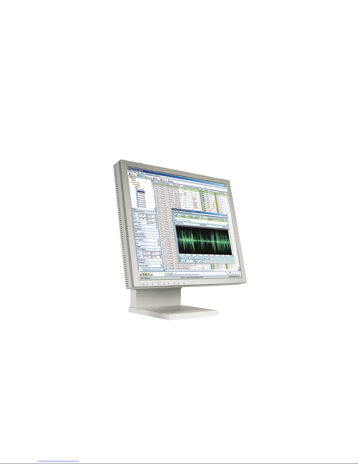
VOCORD Phobos
Date of issue: April 2006
Версия 2.2.15


Table of Contents
Preface ........................................................................................................................................................ 7
License Agreement ....................................................................................................................................... 9
1. Grant of License for the PHOBOS™ Program ....................................................................................... 9
2. Description of Other Rights and Limitations ......................................................................................... 9
3. Reservation of Rights and Ownership ................................................................................................. 9
4. Limitation on Reverse Engineering, Decompilation, and Disassembly ..................................................... 9
5. No Rental/Commercial Hosting ....................................................................................................... 10
6. Consent to Use of Data ................................................................................................................... 10
7. Links to Third-Party Sites ................................................................................................................. 10
8. Additional Hard and Software/Services ............................................................................................. 10
9. Export Restrictions .......................................................................................................................... 10
10. Termination ................................................................................................................................. 10
11. Limited Warranty .......................................................................................................................... 10
11.1. Limitation on Remedies; no Consequential or Other Damages ................................................ 11
11.2. Your Exclusive Remedy ....................................................................................................... 11
12. Disclaimer of Warranties ............................................................................................................... 11
13. Exclusion of Incidental, Consequential and Certain Other Damages ................................................... 12
14. Limitation of Liability and Remedies ................................................................................................ 12
15. Applicable Law ............................................................................................................................. 12
16. Entire Agreement; Severability ....................................................................................................... 12
1. Introduction ........................................................................................................................................... 13
1.1. General Description ..................................................................................................................... 13
1.2. Areas of Application .................................................................................................................... 13
1.3. System Functionality .................................................................................................................... 13
1.4. Delivery Set ................................................................................................................................. 14
1.5. Date and Time Conventions .......................................................................................................... 15
1.6. Conventions ............................................................................................................................... 15
1.7. Resource Planning ....................................................................................................................... 16
1.7.1. Service Conditions ............................................................................................................ 16
1.7.2. Hardware requirements ..................................................................................................... 16
1.7.3. Software Requirements ..................................................................................................... 20
1.8. System Architecture Principles ....................................................................................................... 20
1.8.1. Recording Station ............................................................................................................. 20
1.8.2. Operator Workplace ......................................................................................................... 23
2. Hardware installation ............................................................................................................................. 25
2.1. Card installation .......................................................................................................................... 25
2.2. Signal sources and connection cables ............................................................................................ 26
2.2.1. PHOBOS Audio ................................................................................................................ 26
2.2.2. PHOBOS Video ................................................................................................................. 27
2.2.3. PHOBOS Digital ................................................................................................................ 27
2.2.4. PHOBOS E1 ..................................................................................................................... 31
2.3. Connectors and jumpers .............................................................................................................. 32
2.3.1. PHOBOS™ A2 USB Adapter .............................................................................................. 32
2.3.2. PHOBOS™ A4 Adapter .................................................................................................... 33
2.3.3. PHOBOS™ A4U Adapter ................................................................................................... 35
2.3.4. PHOBOS™ A8 Adapter ..................................................................................................... 35
2.3.5. PHOBOS™ A8 USB Adapter ............................................................................................. 37
2.3.6. PHOBOS™ V8 Adapter .................................................................................................... 38
2.3.7. PHOBOS™ V12 Adapter .................................................................................................. 39
2.3.8. PHOBOS™ V16 Adapter .................................................................................................. 41
2.3.9. PHOBOS™ D4 Adapter ..................................................................................................... 42
2.3.10. VOCORD-iX-E1 Adapter ................................................................................................. 45
2.3.11. PHOBOS™ PRO-E1 Adapter ............................................................................................ 46
2.3.12. ADLink card ................................................................................................................... 47
2.3.13. PHOBOS™ ETAP repeater with LEDs ................................................................................. 48
2.3.14. PHOBOS™ ETAP repeater without LEDs ............................................................................ 49

2.3.15. Two-channel Digital Repeater .......................................................................................... 50
3. Software Installation .............................................................................................................................. 57
3.1. Server software (Recording Station) .............................................................................................. 57
3.1.1. Installing Server Software .................................................................................................. 57
3.1.2. Uninstalling Server Software .............................................................................................. 64
3.2. Client Software ............................................................................................................................ 65
3.2.1. Client software setup ........................................................................................................ 65
3.2.2. Client Software Uninstallation ............................................................................................ 70
3.3. PHOBOS Video ............................................................................................................................ 71
3.3.1. Installing PHOBOS Video ................................................................................................... 71
3.3.2. Uninstalling PHOBOS Video ............................................................................................... 76
3.4. Driver Installation ........................................................................................................................ 77
3.4.1. Initial System Setup ........................................................................................................... 77
3.4.2. Installation of a new adapter model .................................................................................... 77
3.4.3. Adding an adapter of type already present .......................................................................... 77
3.5. Fax messages processing tools ...................................................................................................... 78
3.5.1. Server Software ................................................................................................................ 78
3.5.2. Client software ................................................................................................................. 82
3.6. Installing Pedals ........................................................................................................................... 86
3.7. System Update ............................................................................................................................ 87
3.8. Removing Software ..................................................................................................................... 87
4. Settings ................................................................................................................................................. 89
4.1. Settings Tree ............................................................................................................................... 89
4.2. Logical Channels .......................................................................................................................... 91
4.2.1. Logical Channel Settings .................................................................................................... 92
4.2.2. Adding a logical channel ................................................................................................... 97
4.3. Physical Channels ........................................................................................................................ 98
4.4. Disconnection system .................................................................................................................. 99
4.4.1. Disconnected Cards .......................................................................................................... 99
4.4.2. Disconnected Channels ................................................................................................... 101
4.5. Scheduler ................................................................................................................................. 102
4.5.1. Recording Scheduler ....................................................................................................... 102
4.5.2. Deletion Scheduler ......................................................................................................... 104
4.5.3. Replication Scheduler ...................................................................................................... 107
4.5.4. Profile Scheduler ............................................................................................................. 110
4.5.5. Preset Scheduler ............................................................................................................. 112
4.6. Media ...................................................................................................................................... 114
4.6.1. Volumes ........................................................................................................................ 116
4.7. Interface ................................................................................................................................... 117
4.7.1. Interface ........................................................................................................................ 117
4.7.2. Archive Settings ............................................................................................................. 121
4.8. Journal Settings ......................................................................................................................... 126
4.8.1. Journal View Setup ......................................................................................................... 127
4.8.2. Notification .................................................................................................................... 128
4.9. SMDR ...................................................................................................................................... 133
4.9.1. SMDR module turning on ................................................................................................ 134
4.9.2. Redirection of SMDR information .................................................................................... 135
4.9.3. Protocol Settings ............................................................................................................. 136
4.9.4. Tying the PHOBOS System channels with PBX lines ............................................................. 139
4.10. Switch .................................................................................................................................... 142
4.11. Distributed Mode .................................................................................................................... 144
4.11.1. Adding a Recording Station ........................................................................................... 145
5. Physical Chanels Settings ....................................................................................................................... 149
5.1. Analogue sound processing cards ............................................................................................... 149
5.1.1. Stereo mode .................................................................................................................. 149
5.1.2. Settings for analogue audio cards ..................................................................................... 149
5.1.3. Phone Settings ............................................................................................................... 151
5.1.4. VOX Settings .................................................................................................................. 156
4
MULTICHANNEL AUDIO AND VIDEO RECORDING SYSTEM

5.1.5. Monitoring Channel Settings ........................................................................................... 158
5.1.6. Troubleshooting ............................................................................................................. 159
5.2. Analogue Video Processing Cards ................................................................................................ 161
5.2.1. Video stream multiplexing ............................................................................................... 161
5.2.2. Video cards .................................................................................................................... 162
5.2.3. Video cards settings ........................................................................................................ 163
5.2.4. Motion Detector Settings ................................................................................................. 166
5.2.5. HQW Settings ................................................................................................................ 168
5.2.6. Compression Settings ...................................................................................................... 168
5.2.7. Autotuning .................................................................................................................... 170
5.3. PHOBOS™ D4 Digital Card ......................................................................................................... 170
5.3.1. Protocol Settings ............................................................................................................. 171
5.3.2. Monitoring Channel ....................................................................................................... 172
5.4. Dialogue Window Controls, E1 Cards .......................................................................................... 172
5.4.1. Setting PHOBOS™ E1 card parameters ............................................................................. 172
5.4.2. Physical Channel Settings ................................................................................................ 173
5.5. ADLINK cards ............................................................................................................................ 174
5.5.1. ADLINK cards setup ........................................................................................................ 174
5.5.2. Contact Settings ............................................................................................................. 175
6. Setting the access rights ........................................................................................................................ 177
6.1. Groups ..................................................................................................................................... 177
6.1.1. Adding/Deleting Group .................................................................................................. 178
6.1.2. Editing a Group .............................................................................................................. 178
6.1.3. Group Access Rights ....................................................................................................... 179
6.2. Users ....................................................................................................................................... 183
6.2.1. Adding/Deleting a User .................................................................................................. 184
6.2.2. Editing User Properties .................................................................................................... 185
6.3. Categories ................................................................................................................................ 187
6.3.1. Adding/Deleting a Category ............................................................................................ 187
7. Utilities ................................................................................................................................................ 189
7.1. Configurator ............................................................................................................................. 189
7.1.1. Entering the program ...................................................................................................... 189
7.1.2. Settings Tree .................................................................................................................. 189
7.2. Task Manager ........................................................................................................................... 201
7.2.1. Entering the program ...................................................................................................... 201
7.2.2. The Task Manager Main Window ..................................................................................... 202
7.2.3. Audio channels .............................................................................................................. 202
7.2.4. Transmit Channel A-ter Procedures are similar to those for the ordinary Black List and White
List utilities, but use the special attributes applying to mobile equipment. ....................................... 209
7.2.5. Transmit Channel IPtel ..................................................................................................... 217
7.3. Event Viewer ............................................................................................................................. 221
7.3.1. Entering Event Viewer utility ............................................................................................ 221
7.3.2. The Event Viewer utility main window .............................................................................. 221
7.4. File Import ................................................................................................................................ 223
7.4.1. Entering File Import utility ................................................................................................ 223
7.4.2. The File Import utility main window .................................................................................. 224
7.4.3. Explorer ......................................................................................................................... 224
7.4.4. Record Properties ........................................................................................................... 225
7.4.5. Status Table ................................................................................................................... 225
7.5. LogConfigTest ........................................................................................................................... 226
© V
© Vococoror
d T
d T
echnologie
echnologie
s L
s Ltdtd5
MULTICHANNEL AUDIO AND VIDEO RECORDING SYSTEM


Preface
This Administrator's Guide for PHOBOS™ system, developed by 'Vocord Telecom', is designated for advanced users.
It includes user interface specification, and installation, configuration and administering guide.
Read the License Agreement before you start with the Administrator's Guide.


License Agreement
IMPORTANT - READ CAREFULLY:
This End-User License Agreement ("EULA") is a legal agreement between you (either an individual person or a single
legal entity) and the Licensor for the Vocord Technologies hard and software technology that displays this EULA,
which includes any associated media and Vocord Technologies Internet-related services (the "Software"). For purposes
of this EULA, the term "Licensor" refers to Vocord Technologies Ltd. An amendment or addendum to this EULA may
accompany the Hard and Software. YOU AGREE TO BE BOUND BY THE TERMS OF THIS EULA BY INSTALLING,
COPYING, OR USING THE HARD AND SOFTWARE. IF YOU DO NOT AGREE, DO NOT INSTALL, COPY, OR USE THE
HARD AND SOFTWARE; YOU MAY RETURN IT TO YOUR PLACE OF PURCHASE FOR A FULL REFUND, IF APPLICABLE.
1. Grant of License for the PHOBOS™ Program
Provided you comply with all terms and conditions of this EULA, this EULA grants you the following rights:
1. Installation and use. You may install and use the Hardware and a copy of the Software in accordance with the
end user license agreement that accompanied your Hard and Software Product.
2. License Grant for Documentation. The documentation that accompanies the Hard and Software is licensed for
internal, non-commercial reference purposes only.
2. Description of Other Rights and Limitations
You may not use any Vocord Technologies Internet-based services associated with the Software in any manner that
could damage, disable, overburden, or impair such services or interfere with any other party's use and enjoyment of
them. You may not attempt to gain unauthorised access to any service, account, computer systems or networks associated with the Internet-based services.
3. Reservation of Rights and Ownership
The Licensor reserves all rights not expressly granted to you in this EULA. The Hard and Software are protected by
copyright and other intellectual property laws and treaties. The Licensor or its suppliers own the title, copyright, and
other intellectual property rights in the Hard and Software. The Software is licensed, not sold. This EULA does not
grant you any rights to trademarks or service marks of the Licensor.
4. Limitation on Reverse Engineering, Decompilation,
and Disassembly
You may not reverse engineer, decompile, or disassemble the Software, except and only to the extent that such
activity is expressly permitted by applicable law notwithstanding this limitation.

5. No Rental/Commercial Hosting
You may not rent, lease, lend or provide commercial hosting services with the Hard and Software.
6. Consent to Use of Data
You agree that the Licensor and its affiliates may collect and use technical information gathered as part of the product
support services provided to you, if any, related to the Software. The Licensor may use this information solely to improve
its products or to provide customised services or technologies to you and will not disclose this information in a form
that personally identifies you.
7. Links to Third-Party Sites
The Licensor is not responsible for the contents of any third-party sites or services, any links contained in third-party
sites or services, or any changes or updates to third-party sites or services. The Licensor is providing these links and
access to third-party sites and services to you only as a convenience, and the inclusion of any link or access does not
imply an endorsement by the Licensor of the third-party site or service.
8. Additional Hard and Software/Services
This EULA applies to updates, supplements, add-on components, or Internet-based services components, of the
Software that the Licensor may provide to you or make available to you after the date you obtain your initial Hard or
copy of the Software, unless they are accompanied by separate terms. The Licensor reserves the right to discontinue
Internet-based services provided to you or made available to you through the use of the Software.
9. Export Restrictions
You acknowledge that the Hard and Software are subject to UK export jurisdiction. You agree to comply with all applicable international and national laws that apply to the Hard and Software, including the UK Export Administration
Regulations, as well as end-user, end-use, and destination restrictions issued by UK and other governments.
10. Termination
Without prejudice to any other rights, the Licensor may terminate this EULA if you fail to comply with the terms and
conditions of this EULA. In such event, you must destroy all copies of the Software and all of its component parts.
11. Limited Warranty
Vocord Technologies warrants that the HARD and SOFTWARE will perform substantially in accordance with the accompanying materials for a period of ninety (90) days from the date of receipt. If an implied warranty or condition
is created by your state/jurisdiction and federal or state/provincial law prohibits disclaimer of it, you also have an
implied warranty or condition, BUT ONLY AS TO DEFECTS DISCOVERED DURING THE PERIOD OF THIS LIMITED
WARRANTY (NINETY DAYS). AS TO ANY DEFECTS DISCOVERED AFTER THE NINETY (90) DAY PERIOD, THERE IS
10
LICENSE AGREEMENT

NO WARRANTY OR CONDITION OF ANY KIND. Some states/jurisdictions do not allow limitations on how long an
implied warranty or condition lasts, so the above limitation may not apply to you. Any supplements or updates to the
SOFTWARE, including without limitation, any (if any) service packs or hot fixes provided to you after the expiration
of the ninety (90) day Limited Warranty period are not covered by any warranty or condition, express, implied or
statutory.
11.1. Limitation on Remedies; no Consequential or Other
Damages
Your exclusive remedy for any breach of this Limited Warranty is as set forth below. Except for any refund elected by
Vocord Technologies, YOU ARE NOT ENTITLED TO ANY DAMAGES, INCLUDING BUT NOT LIMITED TO CONSEQUENTIAL
DAMAGES, if the SOFTWARE does not meet Vocord's Limited Warranty, and, to the maximum extent allowed by
applicable law, even if any remedy fails of its essential purpose. The terms of Section 13 below ("Exclusion of Incidental,
Consequential and Certain Other Damages") are also incorporated into this Limited Warranty. Some states/jurisdictions
do not allow the exclusion or limitation of incidental or consequential damages, so the above limitation or exclusion
may not apply to you. This Limited Warranty gives you specific legal rights. You may have others which vary from
state/jurisdiction to state/jurisdiction.
11.2. Your Exclusive Remedy
Vocord's and its suppliers' entire liability and your exclusive remedy shall be, at Vocord's option from time to time exercised subject to applicable law, (a) return of the price paid (if any) for the Hard or Software, or (b) repair or replacement of the Hard or Software, that does not meet this Limited Warranty and that is returned to Vocord Technologies
with a copy of your receipt. You will receive the remedy elected by Vocord Technologies without charge, except that
you are responsible for any expenses you may incur (e.g. cost of shipping the Hard or Software to Vocord). This Limited
Warranty is void if failure of the Hard or Software has resulted from accident, abuse, misapplication, abnormal use
or a virus. Any replacement Hard or Software will be warranted for the remainder of the original warranty period or
thirty (30) days, whichever is longer. Outside the UK, neither these remedies nor any product support services offered
by Vocord are available without proof of purchase from an authorised international source. To exercise your remedy,
contact Vocord Technologies.
12. Disclaimer of Warranties
THE LIMITED WARRANTY THAT APPEARS ABOVE IS THE ONLY EXPRESS WARRANTY MADE TO YOU AND IS PROVIDED
IN LIEU OF ANY OTHER EXPRESS WARRANTIES (IF ANY) CREATED BY ANY DOCUMENTATION OR PACKAGING.
EXCEPT FOR THE LIMITED WARRANTY AND TO THE MAXIMUM EXTENT PERMITTED BY APPLICABLE LAW, Vocord
Technologies AND ITS SUPPLIERS PROVIDE THE SOFTWARE AND SUPPORT SERVICES (IF ANY) AS IS AND WITH ALL
FAULTS, AND HEREBY DISCLAIM ALL OTHER WARRANTIES AND CONDITIONS, EITHER EXPRESS, IMPLIED OR
STATUTORY, INCLUDING, BUT NOT LIMITED TO, ANY (IF ANY) IMPLIED WARRANTIES, DUTIES OR CONDITIONS
OF MERCHANTABILITY, OF FITNESS FOR A PARTICULAR PURPOSE, OF ACCURACY OR COMPLETENESS OR RESPONSES,
OF RESULTS, OF WORKMANLIKE EFFORT, OF LACK OF VIRUSES AND OF LACK OF NEGLIGENCE, ALL WITH REGARD
TO THE HARD AND SOFTWARE, AND THE PROVISION OF OR FAILURE TO PROVIDE SUPPORT SERVICES. ALSO, THERE
IS NO WARRANTY OR CONDITION OF TITLE, QUIET ENJOYMENT, QUIET POSSESSION, CORRESPONDENCE TO DESCRIPTION OR NON-INFRINGEMENT WITH REGARD TO THE SOFTWARE.
© V
© Vococoror
d T
d T
echnologie
echnologie
s L
s Ltdtd11
LICENSE AGREEMENT

13. Exclusion of Incidental, Consequential and Certain
Other Damages
TO THE MAXIMUM EXTENT PERMITTED BY APPLICABLE LAW, IN NO EVENT SHALL Vocord Technologies OR ITS
SUPPLIERS BE LIABLE FOR ANY SPECIAL, INCIDENTAL, INDIRECT, OR CONSEQUENTIAL DAMAGES WHATSOEVER
(INCLUDING, BUT NOT LIMITED TO, DAMAGES FOR LOSS OF PROFITS OR CONFIDENTIAL OR OTHER INFORMATION,
FOR BUSINESS INTERRUPTION, FOR PERSONAL INJURY, FOR LOSS OF PRIVACY, FOR FAILURE TO MEET ANY DUTY
INCLUDING OF GOOD FAITH OR OF REASONABLE CARE, FOR NEGLIGENCE, AND FOR ANY OTHER PECUNIARY OR
OTHER LOSS WHATSOEVER) ARISING OUT OF OR IN ANY WAY RELATED TO THE USE OF OR INABILITY TO USE THE
SOFTWARE, THE PROVISION OF OR FAILURE TO PROVIDE SUPPORT SERVICES, OR OTHERWISE UNDER OR IN
CONNECTION WITH ANY PROVISION OF THIS EULA, EVEN IN THE EVENT OF THE FAULT, TORT (INCLUDING NEGLIGENCE), STRICT LIABILITY, BREACH OF CONTRACT OR BREACH OF WARRANTY OF Vocord Technologies OR ANY
SUPPLIER, AND EVEN IF Vocord Technologies OR ANY SUPPLIER HAS BEEN ADVISED OF THE POSSIBILITY OF SUCH
DAMAGES.
14. Limitation of Liability and Remedies
NOTWITHSTANDING ANY DAMAGES THAT YOU MIGHT INCUR FOR ANY REASON WHATSOEVER (INCLUDING,
WITHOUT LIMITATION, ALL DAMAGES REFERENCED ABOVE AND ALL DIRECT OR GENERAL DAMAGES), THE ENTIRE
LIABILITY OF Vocord Technologies AND ANY OF ITS SUPPLIERS UNDER ANY PROVISION OF THIS EULA AND YOUR
EXCLUSIVE REMEDY FOR ALL OF THE FOREGOING (EXCEPT FOR ANY REMEDY OF REPAIR OR REPLACEMENT
ELECTED BY Vocord Technologies WITH RESPECT TO ANY BREACH OF THE LIMITED WARRANTY) SHALL BE LIMITED
TO THE GREATER OF THE AMOUNT ACTUALLY PAID BY YOU FOR THE SOFTWARE OR U.S. $5.00. THE FOREGOING
LIMITATIONS, EXCLUSIONS AND DISCLAIMERS (INCLUDING SECTIONS 11, 12, AND 13 ABOVE) SHALL APPLY TO
THE MAXIMUM EXTENT PERMITTED BY APPLICABLE LAW, EVEN IF ANY REMEDY FAILS ITS ESSENTIAL PURPOSE.
15. Applicable Law
If you acquired this Hard and Software in the United Kingdom, this EULA is governed by the laws of the UK. If you
acquired this Hard and Software in any other country, then local law may apply.
16. Entire Agreement; Severability
This EULA (including any addendum or amendment to this EULA which is included with the Hard and Software) is
the entire agreement between you and Vocord Technologies relating to the Hard and Software and the support services
(if any) and they supersede all prior or contemporaneous oral or written communications, proposals and representations
with respect to the Hard and Software or any other subject matter covered by this EULA. To the extent the terms of
any Vocord Technologies policies or programs for support services conflict with the terms of this EULA, the terms of
this EULA shall control. If any provision of this EULA is held to be void, invalid, unenforceable or illegal, the other
provisions shall continue in full force and effect.
12
LICENSE AGREEMENT

CHAPTER 1. INTRODUCTION
1.1. General Description
"PHOBOS™ Multichannel Digital Recording System" (here referred as System) is designed for collecting digitalized
compressed audio and video data for its later analysis and/or long-term storage. The PHOBOS system supports unlimited
number of channels simultaneously. Some examples of the System's application are:
• Monitoring and auto recording of phone lines (including digital)
• Monitoring and auto recording of line outputs of various types
• Monitoring and auto recording of video signals received from different cameras
• Synchronised digital audio and video recording (including recording of PAL/SECAM TV broadcasts)
1.2. Areas of Application
The following signal sources can be used for operating the System:
• Analogue phone lines (both PSTN lines and PBX internal lines)
• Digital PBX internal lines
• Microphones (including microphones supplied from a phantom power source)
• Line outputs (line-out) of different devices: mobile radio stations, tape recorders, radio, etc.
• Digital E1 / T1 / Frame Relay / Ethernet digital trunks
• Video cameras of various formats
• Telemetry systems, sensors, and other analogue signal sources
Some organisations that use the System are:
• Security services
• Dispatching and emergency services
• Call centres
• Industrial companies
• Financial institutions (banks, stock exchanges, broker companies)
• PR agencies
1.3. System Functionality
The System performs the following:

• Non-stop audio and video recording, in digital compressed formats, of information received from various sources
• Triplex process support: concurrent recording, playback and channel monitoring
• Support of synchronous audio and video recording mode and subsequent synchronous playback
• Synchronised recording of multiple audio and/or video streams with synchronised playback of these data
• Record export to the standard *.WAV and *.AVI formats
• Fax recognition, CallerID detection, tone and pulse dialling signal distinction
• Archiving (up to 10,000,000 records)
• Auto saving of record attributes: channel name, starting time, duration, CallerID, etc.
• Search and ranking of records by given attributes
• On-the-fly system reconfiguration
• Auto recording, on specified events or on schedule
• Backup of records backup to removable media, manually or automatically
• Transcribing of audio information
• Multi-user operation mode with full-featured access over LAN or Internet
• Support for concurrent full-featured remote access from an unlimited number of users' terminals (including access
over Internet)
• A multilevel system of user access rights
• Distributed architecture, providing integration of an unlimited number of recording stations to a single system
with centralised management
1.4. Delivery Set
The System may be delivered in various ways, including both ready-to-use solutions (in standard desktop or industrial
rack-mounted cases) and single cards installed into the user's PC. In the latter case, the user is able to install and
configure the System using the Administrator’s or User’s Guide.
Table 1.1. Min. Delivery Set:
Quantity (pcs.)Item
1Specialised PC card1
1Connectors to connect signal sources to the card2
1Installation Software CD-ROM3
1Administrator's Guide4
1User’s Guide5
Complete delivery is specified by the corresponding Purchase Agreement.
14
CHAPTER 1. INTRODUCTION

Table 1.2. Base Delivery Set:
Quantity (pcs.)Item
1Installation Software CD-ROM1
1Administrator's Guide2
1User’s Guide3
1.5. Date and Time Conventions
The following conventions are used in the System to designate date and time:
• DD: day of the month
• MM: month of the year
• mon: first 3 month letters
• YYYY: year
• hh: hours
• mm: minutes
• ss: seconds
For reference purposes, the various PHOBOS card types are grouped as follows:
• PHOBOS Audio - analogue audio adapters: PHOBOS™ A2 USB, PHOBOS™ A4, PHOBOS™ A4U, PHOBOS™ A8,
PHOBOS™ A8 USB.
• PHOBOS Digital - digital audio adapters: PHOBOS™ D4, PHOBOS™ D8.
• PHOBOS E1 - E1 lines adapter: PHOBOS™ E1, PHOBOS™ PRO-E1.
• PHOBOS Video - video adapters: PHOBOS™ V8, PHOBOS™ V12, PHOBOS™ V16.
1.6. Conventions
Before you start using this guide, it is important that you understand the typographical conventions that we use. The
conventions used are shown in Table 1.3.
Table 1.3. Conventions
UseConvention
Menu and node names.Help
Menu item and branch names.About
Dialogue window titles and names of dialogue window elements.Users
Keyboard sequences. If the key labels are separated by a comma (for example,
CTRL,ENTER) press the first key and release it; then press the second key and
ENTER, CTRL+N
release it. If the key labels are joined by a <+> sign (for example, CTRL+N), you
should press and hold down the first key while pressing the second the second
one. This is a "hot key" combination.
© V
© Vococoror
d T
d T
echnologie
echnologie
s L
s Ltdtd15
CHAPTER 1. INTRODUCTION
UseConvention
Buttons.Add
Values of attributes, text boxes, sliders, etc.<values>
Additional information.
Important information to be taken into consideration.
1.7. Resource Planning
Vocord Technologies guarantees stable and reliable operation of the PHOBOS™ System only provided that all specified
conditions are met.
1.7.1. Service Conditions
1.7.1.1. Software Operation Requirements
1. Adhering operations, described in this Guide. The Vocord Technologies is not liable for all other operations.
2. Normal System termination.
1.7.1.2. Hardware operation requirements
1. The Recording Station with the cards installed must be grounded.
2. The requirements for cables connecting the System with signal sources are as specified in Signal sources and
connection cables (p. 26).
3. The general requirements for home electronic appliances are followed.
1.7.2. Hardware requirements
1.7.2.1. CPU and RAM Requirements
Refer to Table 1.4, Table 1.5 Table 1.6 for system resource requirements. These sections are composed in dependence
of signal types being recorded.
Table 1.4. Recording Station. System Resources
RAM (MB)CPUChannels (pcs.)
128Intel Pentium III, 500 MHz1-8
16
CHAPTER 1. INTRODUCTION
RAM (MB)CPUChannels (pcs.)
256Intel Pentium III, 500 MHz9-32
512Intel Pentium III, 800 MHz33-64
512Intel Pentium 4, 2 GHz64 and above
For large archives (over 1,000,000 records) RAM greater than 512 MB is recommended.
Table 1.5. Video Recording Station. System Resources
RAM (MB)CPUChannels (pcs.)
256Intel Pentium III, 1 GHz1-4
512Intel Pentium 4 1.6, GHz5-8
512 and aboveIntel Pentium 4, 2.4 GHz9 and above
The tables show values for 25fps@720x576 at full-colour per channel.
Table 1.6. Video Recording Station. System Resources
RAM (MB)CPUChannels (pcs.) (per display page)
256Intel Pentium III, 1000 MHz1-4
512Intel Pentium 4 2, GHz5-8
512Intel Pentium 4 2.4, GHz9-16
To minimise delay in receiving images over a though channel, it is recommended to use motherboards with twochannel RAM based on the Intel 865 chipset.
1.7.2.2. Video card
AGP (Accelerated Graphics Port) cards on the nVidia GPU or ATI motherboards are recommended, with available
memory above 64 MB and the latest driver versions installed (ForceWare for nVidia, Catalyst for ATI).
1.7.2.3. Hard Disks
For hard disks, the NTFS file system is recommended.
Multiple hard disks are recommended for recording more then 8 channels of "live" video at full resolution (25 frames
per second at 720x576 pixels) and high quality. These disks may be used as separate storage units or grouped in
RAID 0 or RAID 5 arrays. In the first case, each video channel should be recorded on the independent disk.
The required disk space is calculated taking into account the number of channels, their data rate, and the required
recording time. Here (Audio Recording (p. 18) Video Recording (p. 18)) the calculation for continuous one channel
recording is presented. Continuous recording to the disk without any loss of current information is achieved by overwriting the "old" records. This happens if the disk is full.
© V
© Vococoror
d T
d T
echnologie
echnologie
s L
s Ltdtd17
CHAPTER 1. INTRODUCTION
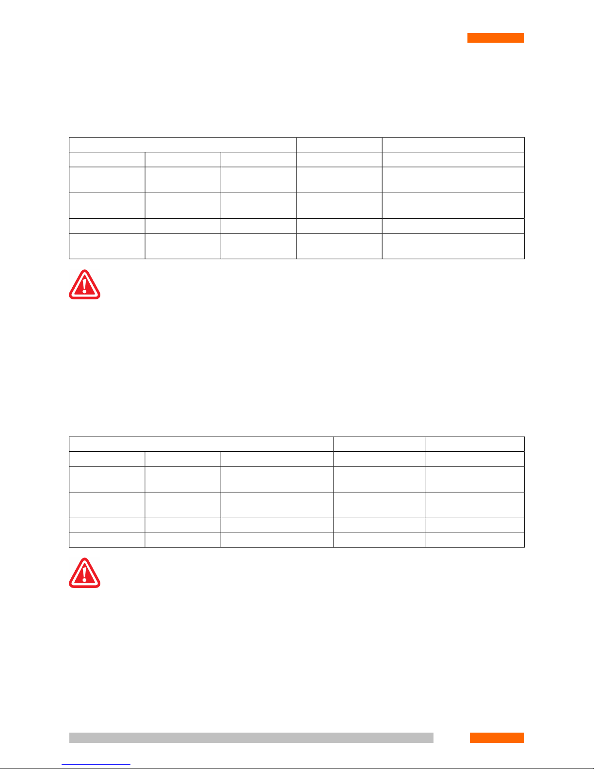
1.7.2.4. Audio Recording
The relation between record size and codec used is shown in Table 1.7.
Table 1.7. Audio Record Size
HDD 10 GBChannel CapacityAudio Record
HoursMb/hourkbpsDescriptionFormat
93109,8625616 kHz no com-
pression
PCM16 @ 16
18654,931288 kHz no compres-
sion
PCM16 @ 8 kHz
37327,4764Compression is 2:1a-law / µ-law
17945,7113,3Compression is
10:1
GSM6.10
Recording at 2:1 compression rate provides sound quality that is virtually identical to the human ear to the quality obtained
in PCM 8 KHz format.
Using the GSM6.10 algorithm saves significant disk space with a minimal loss in sound quality.
Records in PCM 16 KHz format satisfy the requirements of the Russian Ministry of Internal Affairs for audio recordings
used to identify a person by voice.
1.7.2.5. Video Recording
Average data rates for good quality recording in colour mode @ 25fps are shown in Table 1.8.
Table 1.8. Video Record Size
HDD 100 GbChannel loadVideo stream
HoursMb/hour1 frame, kBDescriptionFormat
37 2700 30 720x576 (50
fields)
FULL
74 1350 15 720x288 (25
fields)
HFULL
111 900 10 360x288CIF
2224505 180x144QCIF
The compression algorithm is based on visual quality.
Recording in black-and-white mode reduces the record size by half.
Decreasing the frame rate yields a linear decrease of the required disk space.
Smaller formats give correspondingly longer recording. To re-calculate recording time for the other available formats
(not shown in Table 1.9) the above times should be multiplied by the following factors:
• HFULL (720x288) x2
• CIF (360x288) x3.5
• QCIF (180x144) x6
18
CHAPTER 1. INTRODUCTION
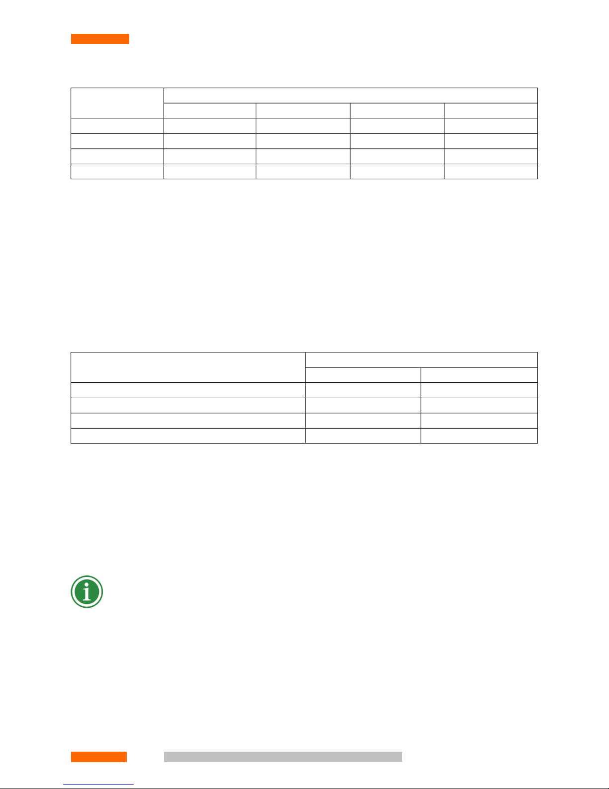
Table 1.9. Time of Continuous Recording
Days of Continuous RecordingFrame (720576)
HDD 180 GBHDD 120 GBHDD 100 GBHDD 80 GB
2.71.81.51.225 fps
5.43.63.02.412 fps
10.87.26.04.86 fps
2315.412.810.23 fps
1.7.2.6. Audio Video Recording
The required disk space is the sum of the audio and video record sizes calculated for the given interval.
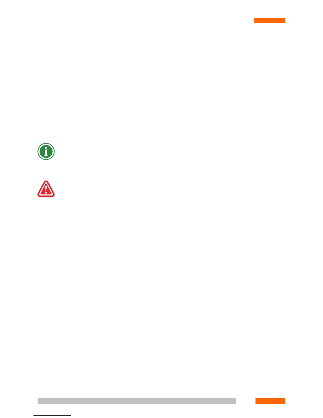
1.7.2.7. Network
Information on possible quantity of simultaneously opened monitoring channels depending on network throughput
capacity is presented in Table 1.10 (see PHOBOS User's Guide).
Table 1.10. Network Throughput
Video stream formatChannel
CIFFULL
1Dedicated channel 2 MB/s
21Ethernet 10 MB/s
168Ethernet 100 MB/s
8040Ethernet 1 GB/s
1.7.2.8. Other Requirements
• 6 GB of free disk space for installation and general System operation
• Free PCI slots on the motherboard for the number of adapters specified by the Contract.
• A free USB port(s), if PHOBOS™ A2 USB or PHOBOS™ A8 USB cards have to be installed.
• VGA colour monitor with 1024x768 resolution.
The content of some windows may be displayed incorrectly at low resolution. This is merely a display artefact: neither
performance nor functionality of the System are lost at resolutions below 1024x768. It is recommended to switch at
least to 32bit colour for better dialogue windows representation.
• Two-button mouse.
• Video card with at least 8 Mb VRAM for videodata browsing and viewing. It is strongly recommended to use DirectX
compatible video cards.
• Audio card for audio data replaying. Model and technical characteristics requirements are highly dependant to
desired playback sound quality.
© V
© Vococoror
d T
d T
echnologie
echnologie
s L
s Ltdtd19
CHAPTER 1. INTRODUCTION
1.7.3. Software Requirements
1.7.3.1. Server (Recording Station)
• Operation System: MS Windows 2000 (recommended) with Service Pack 4 or higher; Windows XP with Service
Pack 2 or higher; Windows 2003.
• Internet Explorer 6.0 or higher
1.7.3.2. Client (Operator's Workplace)
• Operation System: MS Windows 98 SE, Windows 2000 + SP4, Windows XP + SP1
• DirectX 9.0c or higher
If the System is installed on a single computer, the requirements for the server should be satisfied.
Regardless of the interface, in the Recording Station BIOS the Plug&Play OS option must be disabled.
Vocord Technologies guarantees stable and reliable operation of the "PHOBOS™ Multichannel Digital Recording System"
only provided that all conditions specified in the above paragraph are satisfied.
1.8. System Architecture Principles
The System uses a "client-server” architecture. The Server is "Recording Station"; the Client is "Operator Workplace".
1.8.1. Recording Station
A Recording Station is a computer with specified cards and software installed. The Recording Station performs digital
compression and recording to an audio/video disk of the data received from signal sources connected to the specialised
cards.
The Recording Station software is implemented as an Operating System (OS) service that launches on OS start-up.
Therefore the moment the PC is switched on, the Recording Station is ready to work.
MSDE and MS SQL databases are used to provide easy access to the record attributes and the flexible System search
engine.
1.8.1.1. Physical Channels
A physical channel provides the hardware electrical interface for connection of the System to communication lines.
The number of physical channels is strictly determined by the number of channels at the recording cards. Types and
number of physical channels are detected automatically on the System start-up:
• A physical line generates digital compressed data for recording and notifies the System about the channel state.
20
CHAPTER 1. INTRODUCTION

• A telephone station generates data for the telephone lines.
• A motion detector generates data for video.
This information is essential for making a decision to start/stop the process of recording.
A physical channel operates according to:
• the value of the Hook-off Threshold [V] parameter for the telephone channels.
• the value of the VOX Threshold [V] parameter for the channels operating VOX mode, if the line voltage level is
exceeded
• the value of the Operation Threshold parameter for the motion detector, if there is an activity in the selected
area
1.8.1.2. Logical Channels
A logical channel is a group of up to eight physical channels. Recording of all the physical channels joined into one
logical channels happens synchronously.
By default, each physical channel has a corresponding logical channel. The user may create, modify and delete logical
channels while configuring the System. The number of logical channels in the System is virtually unlimited. A physical
channel may make up a part of the various logical channels.
Synchronous recording of all active physical channels attached to a single logical channel starts when any of its physical channels trigger. For the telephone, a line going off-hook triggers the process; for the microphones, exceeding a
signal threshold; and for the video channels, a motion detector operation. The channels operated the recording are
programmed.
Thus the whole picture is received. The playback of videos and of audio recordings from microphones is also synchronous.
The number of logical channels in the System is virtually unlimited. One physical channel could be a member of several
logical channels simultaneously.
The System supports the following logical channel types:
• Audio: a channel consisting of a single audio channel. It operates in Phone, Microphone or Phone/Microphone
modes.
• Video: a channel consisting of a single video channel.
• Video/Audio: a channel consisting of a single audio and a single video channels. The audio channel typically op-
erates in Microphone mode.
• Audio/Audio: logical presentation of a split duplex A-ter channel, connecting a base station controller and switch.
• User-defined: a channel jointing up to eight physical channels of any type. This type provides flexible setting of
registration channels for a particular task.
1.8.1.3. Media
Data media are used to store the records. The System uses the following types of storage media:
© V
© Vococoror
d T
d T
echnologie
echnologie
s L
s Ltdtd21
CHAPTER 1. INTRODUCTION

• Recording Station Hard Disk Drives (HDDs)
• Removable HDDs
• Network disks
• CD, DVD or magneto-optic disks
The media are classified in two principal categories:
• Fixed media are used for on-the-fly recording. Normally one or more Working Station HDs are used as the fixed
media.
• Removable media are used for record backup. Any recording device supported by the Recording Station OS can
be used as a removable media. Normally CD or DVD, magneto-optic disks, removable HDs or any other external
memory devices are used as removable media. These media are used to replicate the records from the fixed media.
The System's continuous records are managed by a stack data storage. Once the real-time archive reaches a specified
size, the oldest records are deleted, unless they are marked for permanent storage.
1.8.1.4. Access Right Management
The access right system provides flexible management of users' rights for monitoring, record playback, and the System
setup.
All users are associated with user groups. Each user group has specified access rights. A user who is a member of
various groups is granted the highest level of access he/she has in those groups.
The System supports several levels of access permission for the attributes of the archive records. For example, some
users are forbidden to view record comments.
It is also possible to give several levels of access for different sections. For example the access to the System setup may
be forbidden.
To distinguish between single-channel and single-record permissions, categories are used. Each record and logical
channel has its own category, which defines access rights for a group of users. All records done over a particular
channel have a category identical to the channel category. If necessary, the record category can be changed from the
Archive section.
Each group has its own access rights to each category. In particular, some channels or records can be hidden from a
particular group of users.
1.8.1.5. Scheduler
The System can operate in fully automatic mode. The following tasks can be performed to a schedule:
• Record creation, deletion, copying and replication
• Profile creation, deletion, copying and applying
• Preset creation, deletion, copying and applying
22
CHAPTER 1. INTRODUCTION

1.8.2. Operator Workplace
An Operator Workplace is the local computer or remote PC, with specialised Software installed, connected to the Recording Station over a TCP/IP network (either LAN or Internet).
An Operator, depending on his/her access rights, can:
• View the status of the connected lines and monitor audio and video channels in real time from the Monitor section.
• Playback a record from the archive, manage archive: Replicate and delete records in the Archive section (see
PHOBOS User's Guide).
• Tune System operation parameters in Settings section (see "Settings" (p. 89)).
• Add or delete users and give permissions from the Access section (see " Setting the access rights" (p. 177)).
• View the event journal from the Journal section (see PHOBOS User's Guide).
© V
© Vococoror
d T
d T
echnologie
echnologie
s L
s Ltdtd23
CHAPTER 1. INTRODUCTION


CHAPTER 2. HARDWARE INSTALLATION
A turnkey solution does not need any hardware installation or setup. You will, however, need to do the following:
1. Connect the monitor, keyboard and mouse to the PC. Connect all the devices (220V), but do not plug the power
cable into the mains until the following steps are complete.
2. Check if all Signal sources and connection cables section requirements are met.
3. Solder the wires of the input lines to the PHOBOS™ connectors, following the instructions provided in the section
" Connectors and jumpers ".
4. Connect the cables to the corresponding adapters.
5. Ground the Workstation case.
6. Connect the system unit power plug to the power outlet (220VAC, unless otherwise specified for custom or
localised products).
Now the PHOBOS™ complex for digital recording is ready for operation. To start working with the System, you need
to install the necessary software (see " Software Installation ").
Prior to installation refer to " Card installation", Signal sources and connection cables , " Connectors and jumpers " if
you're planning to use some special adapter with it's own software or would like to install additional special adapter.
2.1. Card installation
All adapters are PCI cards has to be installed into the system unit of the Recording Station, except for the PHOBOS™
A2 USB and PHOBOS™ A8 USB, which are external devices. Prior to installation, locate the jumpers as described in
the section on " Connectors and jumpers " (p. 32). Follow this order of installation:
1. Turn off your computer and unplug the power cable.
2. Remove the cover of your computer.
3. Locate an available PCI slot. PCI slots are usually white or cream coloured. Remove the back plate (the small piece
of metal that covers the opening for the PCI card on the back cover that you just removed) to allow access to card
external connectors. Insert the card carefully and firmly into the PCI slot.
4. Secure the card with the screw from the back plate.
5. Replace your computer’s cover.
6. Check if all Signal sources and connection cables (p. 26) section requirements are met.
7. Solder the wires of the input lines to the PHOBOS™ connectors, following the instructions provided in the section
" Connectors and jumpers " (p. 32).
8. Connect the cables to the corresponding adapters.
9. Ground the Workstation case.
10. Plug in the computer (220V).

When the computer is switched on and the operating system boots up, all the adapters just installed will be detected
automatically.
The PHOBOS™ A2 USB and PHOBOS™ A8 USB adapters are external devices, and may be installed in "hot" mode
(i.e. while the computer is switched on). Do the following:
1. Plug incoming line connector to the adapter.
2. Connect USB-adapter and Workstation with USB-cable.
3. Proceed to the driver installation (see the Driver Installation (p. 77) section).
2.2. Signal sources and connection cables
All adapters are designed to be configured on a per-channel basis, so that different signal sources may be connected
to the same adapter simultaneously (provided that their type is supported by the adapter).
Signal sources are connected to adapter by different cables depending upon the adapter type.
It is strongly recommended to avoid close placement of all signal cables to electro-magnetic interference sources
(220V and 380V AC power cables, electric motors, etc.). If crossing with power cable is unavoidable, minimum cable
contact should be reached (ideally power and signal cables should be perpendicular to each other).
2.2.1. PHOBOS Audio
As signal sources that do not require power over the channel the following devices could be used:
• Telephone sets
• Microphones
• Linear outputs of mono and stereo audio systems
• Audio outputs of video and TV systems
• Other audio signal sources with impedance less than 2MOhm and output signal band of 6V.
As signal sources powered over the channel line, "Colibri" microphones may be used. The power voltage over the line
is 5V.
It is recommended to make all connections using UTP cat5 cable (category 5 copper twisted pair).
The maximum cable length between the signal source and the adapter is:
• 1 km for connection to a phone set or a microphone with autonomous power, when there is low electromagnetic
interference over the entire cable length.
• 200 m for connection to a microphone powered over the channel line, when there is low electromagnetic interfer-
ence over the entire cable length
• 100 m for any signal sources where there is a significant level of electromagnetic interference.
26
CHAPTER 2. HARDWARE INSTALLATION

2.2.2. PHOBOS Video
The following analogue devices may be used as signal sources:
• CVBS cameras
• S-video cameras
• TV signal lines
• home video cameras
Such devices should be connected by coaxial cable of 75 Ohm impedance (RK–75 or similar).
From the adapter input, the signal should be amplified less than 4.5 dB or attenuated more than -7.5 dB. To satisfy
these conditions, use the following instructions for the video camera gain factor and cable length:
• If the video camera does not amplify the signal, the maximum cable length is calculated according to the following
formula:
Nx = 7.5/No, where
Nx = maximum cable length,
No = linear cable attenuation.
For example, the maximum cable length should be less than 75 metres if the attenuation is 0.1 dB/m.
• If the video camera has a built-in amplifier, select the gain factor (if possible) and/or choose the cable length to
satisfy the following:
4,5>=K+L*No>=-7,5, where
K = video camera gain factor
L = cable length
No = linear cable attenuation.
So this means:
• If the gain factor K cannot be altered, then:
(-4,5)/|No|<= cable length <= (7,5+)/|No|;
• If the cable length L cannot be altered:
|No|*L-7,5 <= video camera gain factor <=4,5+|No|*L.
2.2.3. PHOBOS Digital
The digital PBXs and phone sets listed in Table 2.1 may be used as signal sources.
© V
© Vococoror
d T
d T
echnologie
echnologie
s L
s Ltdtd27
CHAPTER 2. HARDWARE INSTALLATION

Table 2.1. PHOBOS Digital Adapters Signal Sources
Phone set modelStation modelVendor
Any phone sets supported by the stationsAlcatel (connection
only via the repeater)
• 4200;
• 4400.
Any phone sets supported by the stationsMerlin LegendAT&T
Avaya (Lucent, AT&T) • 6402;• Definity G3vs
• 6402 D;• Definity G3bes
• 6408+;• Definity G3si
• 6408 D+;• Definity G3R
• 6416 D+;
• 6424 D+;
• XM 24 – DSS-console for 6416 D+ and 6424
D+;
• 8403;
• 8405;
• 8405 D;
• 8410;
• 8410 D;
• 8434;
• DX 24 – DSS-console for 8434 DX;
• Console;
• CallMaster IV;
• CallMaster VI.
Any phone sets supported by the stationsMillenniumeOn Communications
Ericsson • 2600;• BusinessPhone 50;
• 2601;• BusinessPhone 250;
• 2631;• MD 110.
• 2661;
• 2662;
• 3200;
• 3210;
• 3211;
28
CHAPTER 2. HARDWARE INSTALLATION

Phone set modelStation modelVendor
• 3212;
• 3213;
• 3214;
• 3413;
• Series 25xx (without D-channel);
• Terminal.
LG Electronics • LKD 30 LD;• GDK 16;
• LKD 30 DS;• GDK 20 W;
• LKD 8 DS;• GDK 100;
• LKD 2 NS;• GDK 162;
• Series: KD/E xx.• GDK FPII;
• LDK 300.
Any phone sets supported by the stationsSTAREX (without D-channel)
Any phone sets supported by the stationsNEC • NEAX 2000;
• NEAX 2400;
• NEAX 7400.
Nortel Networks • M 2006;• Meridian Option 11 C;
• M 2008;• Meridian Option 11 C Mini;
• M 2008 HF• Meridian Option 51 C;
• M 2616;• Meridian Option 61 C;
• M 2216 ACD;• Meridian Option 81 C.
• M 2317;
• M 3901;
• M 3902;
• M 3903;
• M 3904;
• M 3905.
Norstar 3x8 Modular Compact ICS • M 7310 (T 7310);
• M 7208 (T 7208);
• M 7100 (T 7100).
© V
© Vococoror
d T
d T
echnologie
echnologie
s L
s Ltdtd29
CHAPTER 2. HARDWARE INSTALLATION
Phone set modelStation modelVendor
Series:DCS KX TD 816 KX TD 1232 KX TD 500Panasonic
• 72xx;
• 74xx.
Any phone sets supported by the stationsDBS
Any phone sets supported by the stationsSamsung Electronics • NX (2-cable, without D-channel);
• DCS (2-cable, without D-channel).
Any phone set supporting the following protocols:Siemens • Hicom 100;
• Up;• Hicom 150;
• 0 Up;• Hicom 300;
• 0e;• Hicom 300 E;
• U 200.• Hicom 300 H.
Any phone sets supported by the stationsCoralTadiran Telecom
20-20Teltronics (Harris) • Optic series;
• Optic 10 series.
Any standard ISDN BRI productsAny standard ISDN BRI stationsAny standard ISDN BRI
product vendors
It is recommended to make all connections using UTP cat5 cable (category 5 copper twisted pair).
For adapter connection, a repeater is used. The description and connection scheme are provided on Two-channel Di-
gital Repeater (p. 50).
Here follows the maximum signal cable length table depending on signal source and adapter type it connects. (see
"PHOBOS™ D4 Adapter" (p. 42)).
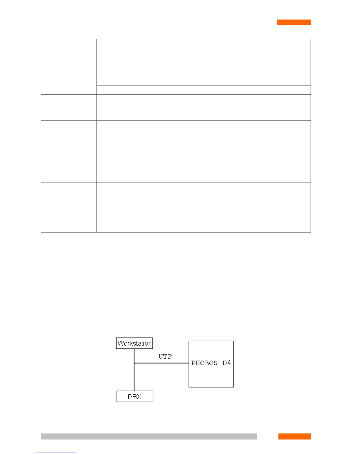
When using direct (serial) connection to the adapter the cable length should not exceed 15 m. Direct connection
scheme is shown in Figure 2.1.
Figure 2.1. Direct adapter connection
30
CHAPTER 2. HARDWARE INSTALLATION
 Loading...