

Page 1
VO-4e
OPERATION MANUAL
May 2019
585.0358.90C
Page 2

VO-4e Product Description
The VO-4e is an enhanced networked audio output expansion device allowing the user to add four linelevel and CobraNet output channels to a Vocia system. The VO-4e can be configured for channel-tochannel or device-to-device failover and uses comprehensive fixed-chain digital signal processing within
the device, including volume control, ducking, equalization, compressor/limiter, speaker crossover, delay,
and output gain. Emergency messages for life safety systems are stored in non-volatile memory. Two
RJ45 connectors on the rear panel of the device provide redundant connectivity to process control data,
audio and power over a single Ethernet cable. In addition to this the VO-4e also has dual inputs for
accepting power from an auxiliary supply. The per-channel paging relay provides a contact closure when
paging is active on an associated channel.
Page 3

VO-4e Setup and Installation
Setup and Use
The Vocia software provides an intuitive interface for configuration, DSP equalization, and programming
of the VO-4e. The information supplied by this manual relates to physical connections and assignment.
For more details on software setup, please consult the Vocia Help File.
Installation
The unit requires one 1.75 inch (44.45 mm) high and 19 inch wide rack space with 17 inch (432 mm)
depth. Mounting the unit using four screws with washers will prevent marring of the front panel. PVC or
nylon washers are appropriate.
Page 4
VO-4e Front
System Indicators
The LED indicators on the front panel provide information and operational status of the unit and
associated output channels. LEDs have been grouped into Chassis and Channel indicators.
Chassis Indicators
These indicators relate to the entire unit (chassis).
PoE
PoE is a green LED indicator that will illuminate when PoE power is applied to the unit via either or both
CobraNet ports.
Aux
Aux is a green LED indicator that will illuminate when an auxiliary DC supply is applied to the unit via
either or both 24V Auxiliary power inputs.
Chassis Fault
Chassis Fault is a amber LED indicator that illuminates when a Chassis Fault has occurred. There are
two types of Chassis Faults that can be reported depending on the severity of the problem. Flashing
amber indicates a Warning that means some aspect of the unit is not performing within normal
specification. Audio may still be passing but if the condition causing the warning is not corrected chassis
failure may occur. Solid amber indicates a fault which means that some aspect of the unit has failed and
audio may no longer be passing through the device. Use Vocia software to determine the specific type of
chassis warning or Fault that has occurred.
Activity
Activity is a two-color LED that indicates the configuration status of the device. A solid green LED
indicates that the unit is configured. A flashing yellow LED indicates the unit is active but unconfigured. A
solid yellow LED indicates the unit is configured and in standby. Standby only occurs when a unit has
been designated as a redundant device when Device Failover is enabled.
Status
Status is a tri-color LED that indicates the health of the hardware. A green LED indicates that the unit
powered up normally. A flashing amber LED is shown briefly during the power-up self-test and will turn
solid green upon successful start. A red LED indicates that the unit experienced a problem during the
power-up self-test.
Channel Indicators
These indicators relate to each of the four channels.
Amp Fault is a amber LED that illuminates when the corresponding Amp Fault Input on the rear of the
unit has been asserted.
Activity is a two-color LED that illuminates green when that channel is configured and actively passing
audio and yellow when that channel is configured and in standby. Standby only occurs when a channel
has been designated as redundant channel in a failover configuration.
Signal is a tri-color LED that illuminates in the following manner when audio signal is present. Detailed
metering of current output levels can be obtained in real time via the Vocia software interface.
Red Amber Green Dark
Signal above clip
threshold
> -2dBFS
Signal above nominal but
below clip threshold
> -18dBFS
< -3dBFS
Signal above minimum but
below nominal threshold
> -48dBFS
< -19dBFS
Signal below
minimum threshold
< -48dBFS
Page 5
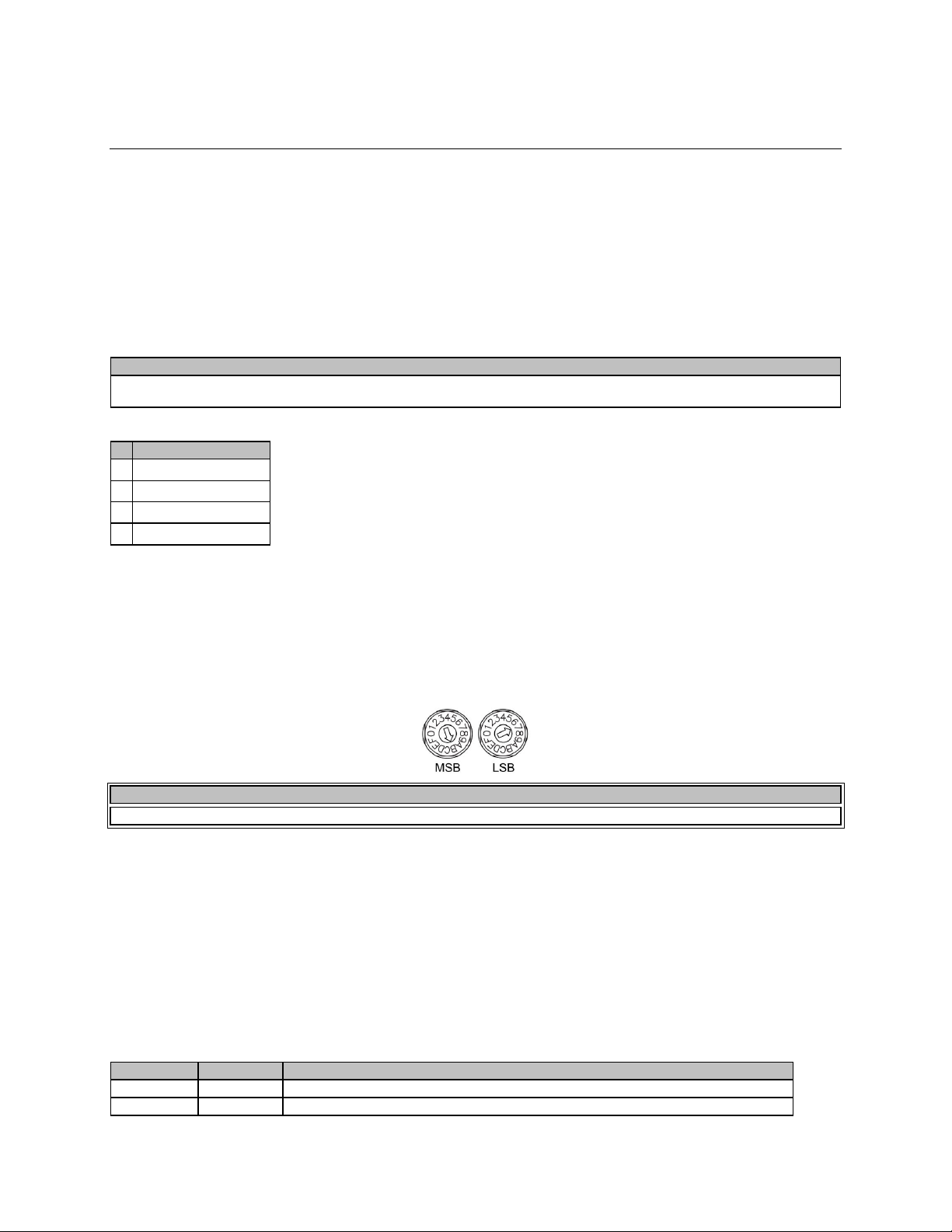
VO-4e Rear
CAUTION
qualified p
erson as required to conform with all local codes.
Pin Function
NOTE
Changes made to the Device ID while connected to the network require a power cycle of the device in order t
o take effect.
Left LED
Right LED
Description
None None No Data
Connectivity or CobraNet activity
None Green
Link established
Power
The VO-4e accepts an external dual 24V DC power source, Power over Ethernet (PoE), or both methods
for redundancy. Both power sources may be connected concurrently, however each must be capable of
supporting the full 15 watt load of the unit. Loss or return of either power source will not result in an
interruption to normal operation as long as one of these power sources remains functional. Monitoring of
power sources is selectable via the Vocia Software.
The power connector is a four-way 5.08mm standard header with mating pluggable screw terminal block
with cable restraint. When power is present at either or both 24V power inputs or the Auxiliary Power
input the corresponding front panel green power LED will illuminate.
Due to potential energy hazard, connections to the Auxiliary Power DC inputs must be made by a qualified electrician or other
1
DC Power 1 24V(+)
2
DC Power 1 24V(-)
3
DC Power 2 24V(+)
4
DC Power 2 24V(-)
Device ID
The rotary ID switches give the unit a unique Device ID. The switches are in hexadecimal format. All units
of the same device type must have a unique Device ID to function properly within a Vocia Paging World.
The Factory Default Device ID is 01. A Device ID of 00 is invalid and cannot be used.
To assign a Device ID of hex 07, leave the MSB switch on 0 and turn the LSB switch to 7. Device ID
switches should be set using a 0.1 inch (2.5mm) to 0.12 inch (3.0mm) flat blade screwdriver.
Network Connections
All CobraNet routing and bundle assignments are processed by the Vocia devices locally. Vocia makes
dynamic use of available bundles in CobraNet. A 100Base-T Ethernet switch (not repeater hub) is
required when networking multiple units. CobraNet utilizes standard CAT5, CAT5e, CAT6, or CAT7
cabling, which has a specified maximum length of 328 feet (100 meters). Additional Ethernet switches, or
switches which provide fiber-optic interface, can be used to extend the physical distance between units
within a network. Please note that CobraNet limits network extensions to seven hops (one-way
transmissions) within a network. The CobraNet network connection is configured with the primary
connector on the left and the secondary (redundant) connector on the right. The primary and secondary
CobraNet ports are provided to facilitate connection redundancy. Each connector provides two LEDs that
indicate Ethernet link and network activity.
Page 6
Flashing yellow
Green
Link established and CobraNet activity detected; The unit is acting as a CobraNet Performer
Flashing yellow
Flashing green
Link established and CobraNet activity detect
ed; The unit is acting as a CobraNet Conductor
Flashing yellow
None CobraNet fault. Check cabling and configuration for errors
Analog Audio Outputs
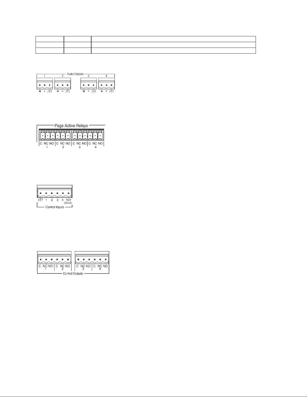
Four 0.2” (5.08mm) three way pluggable barrier strip connectors are provided for analogue audio signal
output. The Vocia software enables a nominal output level of -10dBu, 0dBu or +4dBu to support a wide
range of connection devices.
Page Active Relays
Page Active Relays (PAR) are provided in the form of one Form C (single pole, changeover) relay
presented per output channel. Each PAR connector is a six way 3.5mm pluggable barrier strip connector.
The Page Active relay connections are labeled as follows: • C – Relay Common • NC – Normally Closed •
NO – Normally Open
Control Inputs
Four separate Control Inputs are provided via a six-way 0.2” (5.08mm) pluggable screw terminal block.
Each Control Input allows for an external voltage-free contact closure to ground to assert a Control Input
Event as configured in Vocia software. In addition to the four control inputs, a ground and 10V reference
Out (100mA) is provided. When configured for device failover the Control Input connections must be
paralleled between the main and failover device.
Control Outputs
Four Control Outputs are provided via two six-way 0.2” (5.08mm) pluggable screw terminal blocks. Each
Output has a Common, Normally Closed (NC) and a Normally Open (NO) connection. Outputs will be
capable of being associated with control Output Events configured in Vocia software. Both NC and NO
connections are able to be used at the same time. When configured in a Failover Mode the Controls
outputs are able to be used to indicate the active state of the respective output channel. When configured
for device failover as NO and NC relay connections are being used, consideration should be given to the
performance of the circuit before and after failover.
Page 7

Amp Fault Inputs
Four amplifier Fault Inputs are provided via a six-way 0.2” (5.08mm) pluggable screw terminal block.
These allow for fault monitoring of the output of the VO-4e as indicated from an external amplifier. By
default each input allows an external voltage-free contact closure to ground to indicate a fault condition
for the corresponding VO-4e Output channel. Inputs are pulled high internally to create a default nonasserted condition. When configured for device failover the Amp Fault Input connections must be
paralleled between the main and failover device. This is software configurable so if inverse operation is
required this can be adjusted per input.
Output Fault Detection (VO-4e output channel used in conjunction with a Vocia End of Line Device
1 [ELD-1])
The VO-4e monitors audio output circuit integrity per channel by monitoring multiple out-of-band
(inaudible), high frequency tones in conjunction with ELD-1 devices that have been assigned to the
relevant channel using the Vocia software. To prevent the possibility of interference with these monitored
tones:
• Recorded audio messages or audio content with continuous or swept tonal components (e.g., alert
tones) should be band limited at 15 kHz during recording;
• Program signal levels should be adjusted to minimize clipping, as severely clipped signals may also
affect these out-of-band fault detection tones.
• The use of shielded speaker cable is not supported;
• Highly capacitive speaker lines or loads may prevent correct operation of the ELD detection system;
• Legacy monitored speaker circuits that use capacitors and resistors or similar methods must have all
legacy monitoring circuitry removed for correct operation of the ELD detection system;
• If legacy speaker systems and speaker wiring are to be re-used, these must conform with the
requirements herein;
• Any external power amplifier equipment must be capable of relaying the out-of-band fault detection
tones to the ELD-1. For reliable performance a frequency response of better than -3dB at 24kHz must
be supported through the amplifier and all speaker wiring up to the End of Speaker Line connections
on the ELD-1s;
• The amplifier gain or level control must be set so that nominal output level from the VO-4e (-10dBu,
0dBu or +4dBu; as set in Vocia software) delivers an output level from the amplifier 6dB below the
amplifier maximum output level (clip level). This setting must be accurate and must remain constant for
predictable operation of ELD-1 units.
Failover Modes
Device-to-Device or Channel-to-Channel failover modes are supported. Only one type of failover mode
can be implemented per device.
Device-to-Device Failover
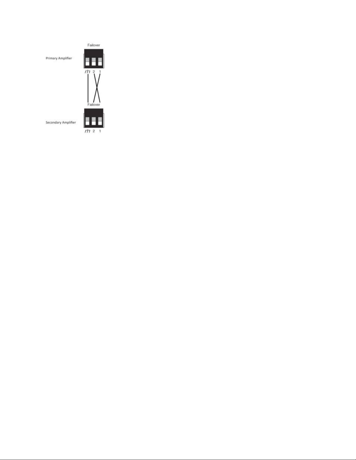
VO-4e units provide for Device-to-Device failover when a fault is detected. A Failover Link Cable must be
connected between the primary and the redundant units as shown. Connect ground to ground, and Pin 1
of the primary device to Pin 2 of the redundant device; connect Pin 2 of the primary device to Pin 1 of the
redundant device.
Page 8
Failover is triggered by any of the following conditions:
• Chassis Fault
• Channel Fault
• Loss of power
• Loss of CobraNet link
• Loss of Failover Link Cable
• ELD-1 / speaker line Fault (if enabled in software)
• External amplifier Faults being asserted
Only Chassis and Channel Faults trigger the Device failover mechanism. Abnormal conditions that do not
immediately impair audio will appear as warnings but will not trigger failover. After a failover condition has
been asserted, a power cycle of the units is required to recover from the failover. This can be done either
by physically repowering the devices or by performing a ‘Device Reset’ in the Vocia software via the Test
tab of the device dialog. The units are required to be reset within 10 seconds of each other in order to
ensure the primary device resumes control.
Channel-to-Channel Failover
Channel-to-Channel failover is supported as 1:1 Channel. In this configuration, channel pairs can be
specified and adjacent channels will act as a redundant backup. Channel 2 will act as backup for Channel
1 and Channel 4 will act as backup for Channel 3. Channel failover is triggered by either a Channel
Failure Fault, an ELD-1/Speaker Line Fault (if enabled in software) or an amplifier Fault Input being
asserted. The VO-4e will return to normal operation after the Fault condition is cleared and the unit is repowered or reset via the Test tab in the Properties sheet.
 Loading...