

Page 1
PSKIT-1
OPERATION MANUAL
May 2019
585.0404.90A
Page 2

PSKIT-1 Product Description
The PSKIT-1 is a standalone Paging Station Kit designed to allow for direct connection to third-party
equipment such as fireman’s microphone stations or custom designed fire panels. The PSKIT-1 features
embedded DSP and on-board memory to support standard and advanced public address and mass
notification functionalities. The PSKIT-1 can store 999 user-configurable Page Codes. Additionally, all
device-specific configuration information is stored locally, which means the PSKIT-1 does not rely on a
centralized controller for processing and page routing.
Page 3

PSKIT-1 Setup and Installation
Setup and Use
The Vocia software provides an intuitive interface for configuration, DSP equalization, and programming
of the PSKIT-1. The information supplied by this manual relates to physical connections and assignment.
For more details on software setup, please consult the Vocia Help File.
Installation
Install the unit away from heat sources, such as vents and radiators, and in rooms with adequate
ventilation. Ensure that air can circulate freely behind, beside, and above the unit. Do not exceed the
maximum ambient operating temperature of 32° - 108° F (0° - 42°C). Be aware of conditions in an
enclosed rack that may cause the temperature to exceed ambient room conditions.
Page 4
PSKIT-1 Front
CAUTION
qualified person
LED Description
None No power
Solid
green
Note
Do not use both the internal and external microphone connections at the same time.
Pin Out
Function
Power Indicator
Due to potential energy hazard, connections to the Auxiliary Power 24V DC inputs must be made by a qualified electrician or other
The Vocia PSKIT-1 is capable of operation from both PoE and 24V DC power. If both are being used,
PoE power is given priority. The Power Indicator LED behaves in the following manner:
Powered
CONNECTIONS
Power
The PSKIT-1 supports powering via 802.3af or 802.3at (Type 1) PoE switches or external PoE Supplies.
Alternatively the device can be powered using the Power connector and an external 24V DC supply. Both
supplies can be connected at the same time without affecting the unit. Upon loss of one power source the
unit automatically switches to the other source without interrupting device operation.
Microphone
A microphone may be connected using the external 3-pin balanced microphone input provided. The
default nominal input level is -50dBu. Phantom power is not available on this input. If using this input, the
microphone and its connection will not be monitored.
The PSKIT-1 also includes a 5-pin internal connector for supporting a Biamp monitored microphone
(optional accessory). This connection is not accessible from the outside of the enclosure and must only
be used with a Biamp supplied microphone. If the internal connector is being used with a monitored
microphone, the LK1 and LK2 jumpers must be removed. By default the jumpers are installed, which
disables the monitoring functionality so that a standard (3-pin) microphone may be used.
PTT Input
The Push-to-Talk function will be activated when the PTT pin is connected to Ground.
General Purpose Inputs
The PSKIT-1 supports 12 unmonitored Control Inputs for connection to a keypad interface numbered 0
through 9, as well as inputs for a Next and Previous scroll button. Each Control Input is activated with a
momentary connection to Ground. Only one pin can be selected at once.
General Purpose Outputs
Two General Purpose Outputs are used to indicate the Wait and Talk states.
Once the PTT is active the “Wait” output will assert while the system establishes the necessary audio
paths, checks for zone availability
and plays the chime (if selected). The “Talk” output will assert once the audio path is live.
RS-232
A female RS-232 serial port is provided for Vocia Text Protocol (VTP) connectivity. Please refer to the
software help file for all supported
commands.
Page 5
Pin 2 Transmit Data TXD
output
Pin 3 Receive Data RXD input
Pin 5 GND / 0V
Aux Port
Left LED
Right LED
Description
None None No power or d
ata connectivity. Please check the PoE network connection.
Amber
Flashing
Green
Link established and CobraNet activity detected (normal operation).
Flashing
Amber
operating as CobraNet
Conductor.
Flashing
Amber
NOTE
Changes made to the Device ID while connected to the network require a power cycle of the device in order to take effect.
A RJ-45 connector is available internally for use with Biamp accessories. This port is not an Ethernet port
and must not be connected to a
switch, PoE supply, or other Ethernet network devices.
Network Connections
PoE-enabled network switches or PoE midspan adapters must be used to power the unit. These must be
802.3at Type 1 compliant. The maximum cable distance between any unit and an Ethernet switch is 328
feet (100 meters) when using copper cabling. Additional Ethernet switches and/or fiber-optic cable can be
used to further extend distances between units on a network. Please note that CobraNet limits network
extensions to seven hops (one-way transmissions) within a 100Mb network. If other network traffic shares
an Ethernet switch with the Vocia network, a managed switch should be used with separate VLANs.
The connector provides two LEDs that indicate Ethernet link and network activity.
Flashing Green
Link established and CobraNet activity detected (normal operation). Unit is
None
CobraNet Fault. Check cabling and configuration for errors.
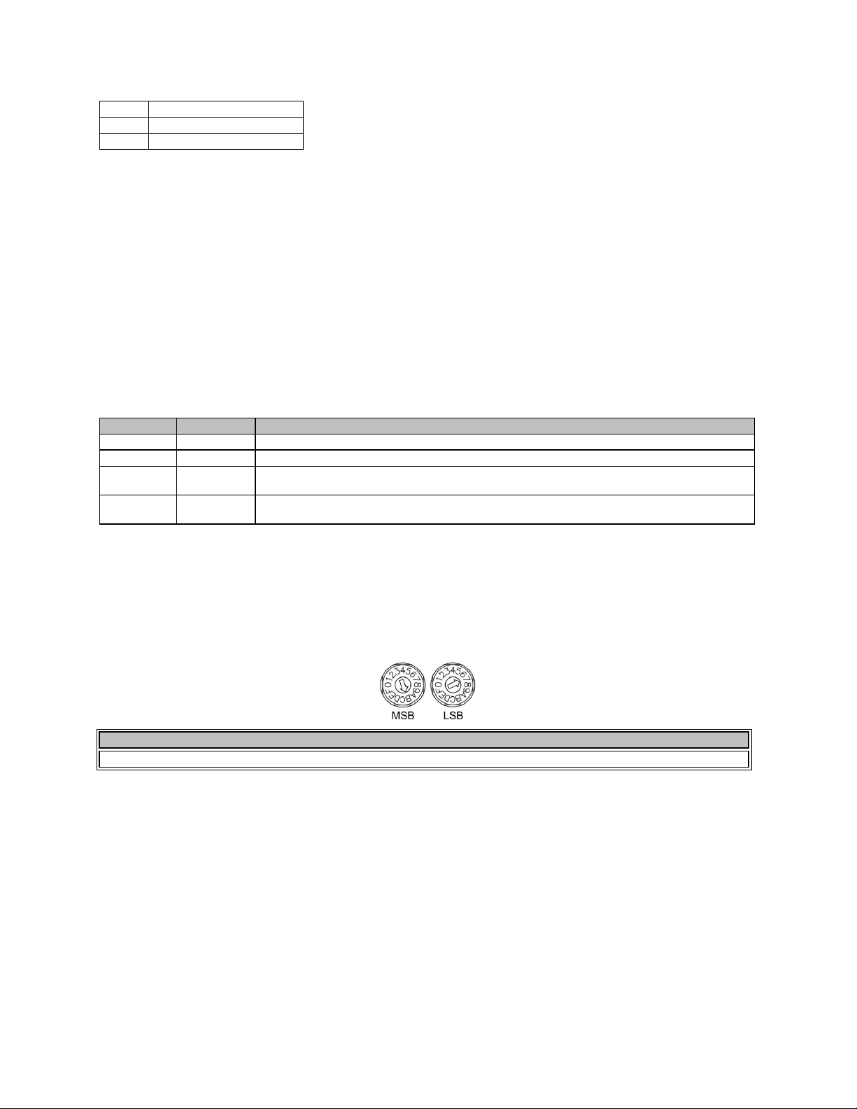
Device ID
The rotary ID switches give the unit a unique Device ID. The switches are in hexadecimal format. All units
of the same device type must have a unique Device ID to function properly within a Vocia Paging World.
The Factory Default Device ID is 01. A Device ID of 00 is invalid and cannot be used.
To assign a Device ID of hex 07, leave the MSB switch on 0 and turn the LSB switch to 7. Device ID
switches should be set using a 0.1 inch (2.5mm) to 0.12 inch (3.0mm) flat blade screwdriver.
 Loading...