


LSI-16 / LSI-16e
OPERATION MANUAL
May 2019
585.0245.90C

LSI-16 Product Description
The LSI-16 serves as an emergency interface between a Vocia system and emergency/fire alarm
systems. While typically powered from a certified 24V DC source, it can also utilize Power over Ethernet
(PoE).
The LSI-16e is an enhancement to the LSI-16 adding 16 additional control inputs. The LSI-16e serves as
an enhanced emergency interface between a Vocia system and emergency/fire alarm systems. While
typically powered from a certified 24V DC source, it can also utilize Power over Ethernet (PoE).

LSI-16 Setup and Installation
Setup and Use
The LSI-16 and LSI-16e govern the emergency functions of a Vocia system, monitoring and reporting
faults and alarm conditions through indicators and the system software. Incorrect configuration, removal,
or non-installation of some system elements may result in the LSI-16(e) reporting a fault or alarm
condition. This is normal operation. For correct, fault-free operation, inputs and outputs must be
connected to the LSI-16(e) as detailed in this manual. The Vocia software provides the intuitive interface
for configuration, DSP equalization, and programming of the LSI-16 and LSI-16e. For details on software
setup, please consult the Vocia Help File.
Installation
Install the unit away from heat sources, such as vents and radiators, and in rooms with adequate
ventilation. Ensure that air can circulate freely behind, beside, and above the unit. Do not exceed the
maximum ambient operating temperature of 18°-108° F (-8° - 42°C). Be aware of conditions in an
enclosed rack that may cause the temperature to exceed ambient room conditions.
The unit requires one 1.75 inch (44.45 mm) high and 19 inch wide rack space with 10 inch (254 mm)
depth. Mounting the unit using four screws with washers will prevent marring of the front panel. PVC or
nylon washers are appropriate.

LSI-16 Front
Front Panel
The LSI-16/LSI-16e features twenty-three LEDs on the front plate (from left to right).
Power
The first LED on the left will illuminate green if the unit is powered by main or PoE supplies.
General Alarm
This LED will illuminate red if the LSI-16/LSI-16e receives an alarm signal from an external emergency
detection system (e.g. a fire alarm system) via the Alarm inputs to the LSI-16/LSI-16e. This LED indicates
the general alarm state:
• Solid red - The LSI-16/LSI-16e has received an alarm signal from an external emergency detection
system (e.g. fire alarm system).
• Flashing red - The LSI-16/LSI-16e has received a general alarm silence from an external emergency
detection system (e.g. fire alarm system).
General Fault
This LED will illuminate yellow if there is a fault in the system that does not affect the delivery of a warning
message.
Power Supply Fault
This LED will illuminate yellow if LSI-16/LSI-16e is operating on a PoE supply but the main 24V supply
fails or an external power supply fault is signaled to the LSI-16/LSI-16e.
Protection Fault
This LED will illuminate yellow if a system amplifier channel fails and this failure does not prevent an
emergency zone voice announcement. Note: failures that do affect emergency zone voice
announcements will result in a system fault.
Path Fault
This LED will illuminate yellow if a fault in a transmission path is detected. The path integrity is tested from
microphone capsule to end of loudspeaker lines if optional Vocia ELD-1 devices are fitted at the end of
the loudspeaker lines.
System Fault
This LED indicates the integrity of the system:
• Flashing yellow - The unit has a fault that may prevent the reliable operation of life safety
announcement functions.
• Not illuminated - The unit is operational without any faults that may prevent reliable operation of life
safety announcement functions.
Because it indicates a potentially serious condition, the presence of a System Fault extinguishes
indicators for PSU, Path and Protection faults so as to focus attention on the primary fault. However,
individual PSU, Path and Protection faults are still shown in the system software and signaled to
individual fault outputs as described below. The LSI-16/LSI-16e will always power up in the system fault

condition. Manual intervention is required to take the LSI-16/LSI-16e out of this condition. Note: this
power up condition does not prevent emergency zone voice announcements provided that the system is
operating reliably.
General Purpose LEDs (LEDs 8 - 23)
These LEDs indicate functionality of the general purpose inputs on the LSI-16e or of the LSI-16 that has
been updated with an Interface Module 16 (IM-16). On an LSI-16 without an option board, these LEDs
remain inactive.
• Solid Red: An Alarm is active on the associated input.
• Flashing Red: An Alarm in the system has been silenced.
• Solid Amber: A Fault is active on the associated input.
• Flashing Amber: An input configured as “high range - monitored” exhibits a monitoring fault.

NOTE
Changes made to th
e Device ID while connected to the network require a power cycle of the device in order to take effect.
Left LED
Right LED
Description
None None No Data Connectivity or CobraNet activity
None Green
Link established
Flashing yellow
Green
Link established and CobraNet activity detected; The unit is acting as a CobraNe
t Performer
Flashing yellow
Flashing green
Link established and CobraNet activity detected; The unit is acting as a CobraNet Conductor
Flashing yellow
None CobraNet fault. Check cabling and configuration for errors
LSI-16 Rear
Power
The LSI-16(e) accepts an external dual 24V DC power source, Power over Ethernet (PoE), or both
methods for redundancy. Both power sources may be connected concurrently, however each must be
capable of supporting the full 15 watt load of the unit. Loss or return of either power source will not result
in an interruption to normal operation as long as one of these power sources remains functional.
Monitoring of power sources is selectable via the Vocia Software.
Device ID
The rotary ID switches give the unit a unique Device ID. The switches are in hexadecimal format. All units
of the same device type must have a unique Device ID to function properly within a Vocia Paging World.
The Factory Default Device ID is 01. A Device ID of 00 is invalid and cannot be used.
To assign a Device ID of hex 07, leave the MSB switch on 0 and turn the LSB switch to 7. Device ID
switches should be set using a 0.1 inch (2.5mm) to 0.12 inch (3.0mm) flat blade screwdriver.
Network Connections
All CobraNet routing and bundle assignments are processed by the Vocia devices locally. Vocia makes
dynamic use of available bundles in CobraNet. A 100Base-T Ethernet switch (not repeater hub) is
required when networking multiple units. CobraNet utilizes standard CAT5, CAT5e, CAT6, or CAT7
cabling, which has a specified maximum length of 328 feet (100 meters). Additional Ethernet switches, or
switches which provide fiber-optic interface, can be used to extend the physical distance between units
within a network. Please note that CobraNet limits network extensions to seven hops (one-way
transmissions) within a network. The CobraNet network connection is configured with the primary
connector on the left and the secondary (redundant) connector on the right. The primary and secondary
CobraNet ports are provided to facilitate connection redundancy. Each connector provides two LEDs that
indicate Ethernet link and network activity.

NOTE
Additional (Auxiliary) power is also provided via a dedicated 24V connection
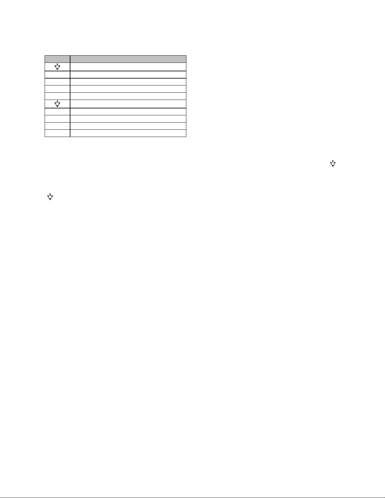
Marking
Function
Ground
1 Sounder Output / Silence
Input
2 System Fault Reset Input
3 Voice Alarm active
4 General Fault
5 PSU Fault
6 Protection Fault
7 Path Fault
8 External Supply Over
-
voltage Monitor
10V 10V Out
Using PoE Power
The LSI-16 and LSI-16e have dual, monitored PoE capable Ethernet ports enabled by default. For fault tolerant or compliant
systems both interfaces must be used.
LSI-16 Ethernet connection using a PoE switch:
LSI-16e Ethernet connection using a PoE injector:
Monitored I/O
Two black five-position connectors are located next to the rotary switches. These are predominantly used
for monitored inputs and outputs (I/O) to external lamps or sounders. Individual connections are labeled 1
through 8. One connection is configured for use as both an input and an output (1) and one as an input
(2) (see table below for connector assignments).

The inputs/outputs will sink current (pull low) when active (see the Specifications section of this document
for more details). The desired load (lamp, LED, etc.) must be connected between the input/output
terminal and a positive voltage reference.
It should be noted that external switches and a sounder connected to the first two inputs are typically
mandatory for standards compliance. The location and physical attributes of these items may be required
to conform with local norms.
For each of these inputs/outputs, a load must be connected between each output and the positive voltage
source. If any output on terminals 1 through 8 is unused, the output must be connected through an
external resistor to the positive side of the voltage source (either 10V Out or user-supplied external
source). To ensure correct functionality, the value of each resistor should be 22kΩ. An internally derived
10V source is provided at the 10V Out terminal; however, the total current available from this pin is limited
to 100mA. This voltage source may be used for external devices provided the total load is less than
100mA. For higher-current devices, a user-supplied external voltage source of up to 35V may be used,
with the negative side connected to the pin. Due to monitoring constraints, it is impossible to use both the
internal 10V source and an external source. For monitoring purposes, the positive side of the voltage
source (either 10V Out or user-supplied external source) must be connected to the External Supply Overvoltage Monitor (terminal 8), as well as supplying voltage to external devices.
Sounder Output/Silence Input
This connection functions as a dual purpose alarm sounder output and silence input.
Sounder Output
This output connects to a local sounder for fault and alarm warnings. A sounder is typically
required for standards compliance. Note: If an emergency microphone is located near the sounder,
it may be configured in Vocia software to mute the sounder while making live announcements.
Silence Input
This input is used to silence the local sounder. The sounder will restart in response to any new
Fault or Alarm.
System Fault Reset Input
This input is required to take the LSI-16/LSI-16e out of System Fault condition. Note: the LSI-16/LSI-16e
will always power up in a system fault state.
Voice Alarm Active
This output is active when messages are playing in response to an alarm input. This output provides
indication of when a message is playing or when a message has been muted.
Constant active output - indicates a message is playing in response to an alarm input.
Cyclic output (1.25Hz) - indicates the message has been muted.
General Fault, PSU Fault, Protection Fault and Path Fault
These outputs will be activated by the same alarm conditions as identically named LEDs on the front
panel. Note however that these outputs will be activated by the faults listed above irrespective of whether
a System Fault has been activated.
The Voice Alarm Active, General Fault, PSU Fault, Protection Fault and Path Fault outputs are monitored
for open-circuit or short-circuit to ground or power supply and for over-voltage on the output pin (>35V
DC). If incorrect conditions are detected a Fault is signaled. Output monitoring facilitates compliance with
voice evacuation standards.
Control Inputs
Two five-position plug-in barrier strip connectors provide control input connections. Eight separate
channels plus two ground pins are provided. Control Inputs are fully isolated from all connections in the
LSI-16/LSI-16e.
Marking
Function
1 PSU Fault
2 Ethernet Fault
3 Voice Alarm Silence from CIE/Fire panel)
4 Voice Alarm Reset (from CIE/Fire panel)
5 Emergency Input 1
6 Emergency Input 2
7 Emergency Input 3
8 Emergency Input 4
Ground
Ground
Input Activation Conditions
Control Inputs 1 & 2
To activate an input it must be connected to an external circuit that returns to either of the two ground ( )
pins. The resistance of this circuit must be less than 4kΩ.
Control Inputs 3 to 8
These inputs must be permanently connected to an external circuit that returns to either of the two ground
( ) pins. The resistance of this circuit must be between 1kΩ and 4kΩ. To activate an input, pull the input
to a voltage between 12 and 24V.
PSU Fault
This input may be derived from the primary 24V power supply to indicate to the LSI-16/LSI-16e if there is
a fault in the power supply. This may be required for standards compliance.
Ethernet Fault
This input can be derived from an Ethernet switch to monitor the Ethernet network connection between
the LSI-16/LSI-16e and amplifier. This may be required for standards compliance.
Voice Alarm Silence from CIE (fire alarm system)
This input is a signal from the CIE (fire alarm system) that will mute emergency messages in all
emergency zones.
Voice Alarm Reset from CIE (fire alarm system)
This input is a signal from the CIE (fire alarm system) that will reset emergency messages in all
emergency zones.
Emergency Inputs
These four inputs are used to connect to the fire alarm control and indicating equipment (CIE) and notify
the LSI-16/LSI-16e that an alarm has occurred on a particular zone. Four such zone inputs may be
connected; one emergency message or mute can be assigned per zone. Additional zone inputs are
available with the IM-16. When an alarm is detected, the Vocia system will enter Emergency Mode as
configured for that input. During Emergency Mode, some or all of the Vocia system will cease normal
operation and operate as programmed for the emergency.
General Purpose Inputs
These connections provide functionality of the option inputs on the LSI-16e or of the LSI-16 that has been
upgraded with an Interface Module (IM-16). On an LSI-16 without an option board, these connections will
remain inactive.
Two connectors, labeled Option A and Option B, are located on the back of the LSI-16e. Each slot
consists of 14 pins which are labeled 1 to 14. Each connector bank allows for the following connection:
• Chassis Ground: One connection per connector bank.
• Isolated Ground: Four connections per connector bank.
• Control Inputs: Eight connections per connector bank.
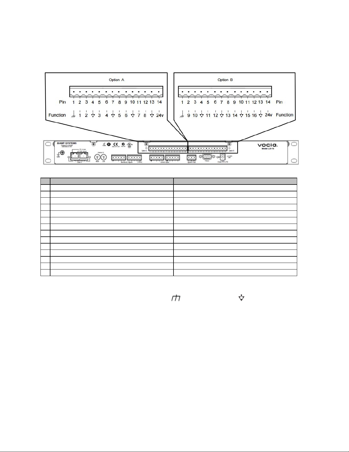
PIN Option A Function
Option B Function
1 Chassis Ground
Chassis Ground
2 General Purpose Input 1
General Purpose Input 9
3 General Purpose Input
2 General Purpose Input 10
4 Isolated Ground
Isolated Ground
5 General Purpose Input 3
General Purpose Input 11
6 General Purpose Input 4
General Purpose Input 12
7 Isolated Ground
Isolated Ground
8 General Purpose Input 5
General Purpose Input 13
9 General Purpose Input 6
General Purpose Input 14
10 Isolated Ground
Isolated Ground
11 General Purpose Input 7
General Purpose Input 15
12 General Purpose Input 8
General Purpose Input 16
13 Isolated Ground
Isolated Ground
14 24V DC (60mA total across
both Option A and B pins)
24V DC (60mA total across both Option A and B pins)
• 24 Volts DC - One output per connector. Internally sourced, this will allow up to 60mA to be shared
over all general purpose inputs.
Connections and Input
Types External Connections Both Chassis Ground ( ) and Isolated Ground ( ) are available on the IM16 connectors.
By default, all input circuits are isolated with respect to the LSI-16 ground. Any external input connections
must be logic referenced to the Isolated Ground. This configuration allows external equipment to be
interconnected to the LSI-16 without ground current interaction between devices.
The IM-16 ground appears on a single terminal (Pin 1) on each of the two connector banks (‘Option A’
and ‘Option B’). This should only be used if circuit isolation is not required and should only be connected
to the cable screen.
The two isolated grounds of the IM-16 board are connected internally. For ease of wiring each connector,
every Control Input pair has an Isolated Ground connection adjacent to it.
Types of Input Circuit
The logic level of each input on the IM-16 may be independently determined in the Vocia software to
operate one of four ways. These are;

• TTL: 2V to 5V logic sense. To enable a TTL input, apply a TTL logic high with respect to Isolated
Ground. This can be configured in software to detect a low to high or high to low transition.
• High Range: To enable a High Range input, use a dry contact to switch the input to a voltage of
24V DC with respect to Isolated Ground. This can be configured in software to detect a low to high
or high to low transition.
• High Range – Monitored: This circuit is implemented in the same way as the ‘High Range’ input.
This option allows monitoring of each input for short to ground and open circuit. In order to sense
open circuit, a terminating resistor must be fitted between each Control Input and Isolated Ground
at the far end of the input circuit being sensed. The IM-16 will sense open circuits on the line
between its input and the terminating resistor. Shorts to Isolated Ground are sensed across the
entire line being monitored. A 6k8Ω resistor should be used for each input. If a monitoring fault is
detected on any input the logic state or transitions on that input will be ignored until the fault is
cleared. High Range – Monitored inputs require a low to high transition to enable the input
(transition direction not configurable).
• Contact Closure: Uses a dry contact without the requirement to use the 24V DC with respect to
Isolated Ground.
System Fault Relay Connection
This relay is activated when the LSI-16/LSI-16e is fully operational. It may be used for informing external
devices about the LSI-16/LSI-16e’s operating conditions or sounding an alarm that indicates the LSI16/LSI-16e is not functioning reliably.
RS232
The RS232 port can be used to send VTP commands to the LSI-16/LSI-16e and monitor Vocia system
health. Please see the software Help File for details.
24V DC Connector and LED
This is the primary (main) power supply input for the LSI-16 and as such must be fed from a suitable
source of 24V DC capable of 15 watts (625mA). The 24V DC supply has to be sourced separately. In
typical installations, this supply will be provided from a power supply compliant with local norms and
required standards (typically battery-backed). The adjacent LED indicates the presence of power.
Sourcing 24V DC for High Range Inputs
The High Range logic inputs should be driven from a contact closure (relay or switch) in connected
equipment. The High Range inputs expect to sense a transition from low-state voltage (0-11V) to highstate voltage (12-30V). A 24V Logic High Reference output voltage is provided by the IM-16 for this
purpose. Alternatively an external 24V reference may be used. If an external supply is used, the ground
connection of the external supply must be wired to the IM-16 Isolated Ground.
IP30 Compliance
The LSI-16 is designed for ingress protection to the IP30 standard. In order to maintain this compliance,
any unused terminal connectors on the back of the unit must be fitted with the supplied terminal blocks.
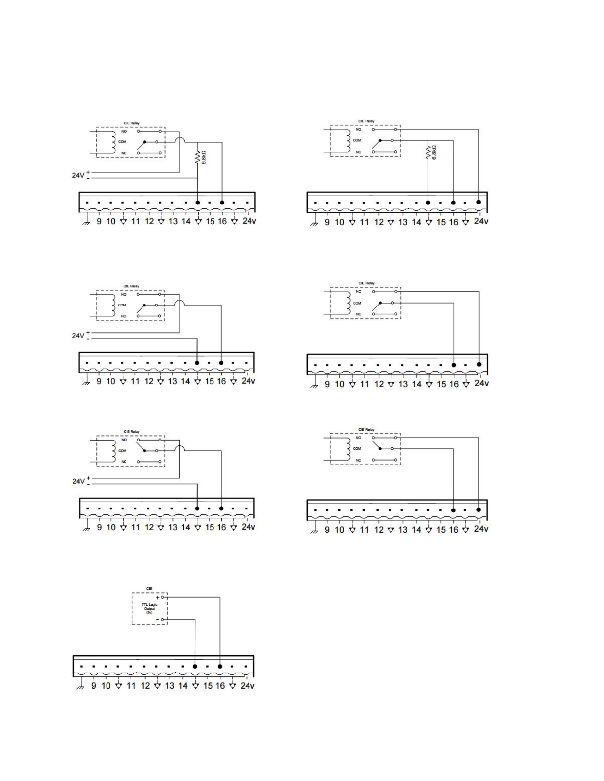
High Range Monitored
24V provided externally) Active State High
(24V provided by IM-16) Active State High
High Range Unmonitored
(24V provided externally) Active State: High
24V (External/CIE Provided) Active State: Low
(24V provided by IM-16) Active State: High
24V (IM-16 Provided) Active State: Low
5V TTL Logic
Active State: Voltage Dependant
 Loading...