

Page 1

GPIO-1
OPERATION MANUAL
0D\
585.0318.90B
Page 2

GPIO-1 Product Description
The GPIO-1 provides 16 general purpose inputs and outputs to control various aspects of a Vocia
system. The GPIO-1 is a monitored device and can be used with an LSI-16e in life safety applications
where more logic inputs or outputs are required. The GPIO-1 has dual powering from PoE Ethernet ports
and alternate powering from dual 24V DC inputs. In the event of power loss, changeover between power
sources will provide uninterrupted operation.
Page 3

GPIO-1 Setup and Installation
Setup and Use
The Vocia software provides an intuitive interface for configuration and programming of the ANC-1. The
information supplied by this manual relates to physical connections and assignment. For more details on
software setup, please consult the Vocia Help File.
Installation
Install the unit away from heat sources, such as vents and radiators, and in rooms with adequate
ventilation. Ensure that air can circulate freely behind, beside, and above the unit. Do not exceed the
maximum ambient operating temperature of 18°-108° F (-8° - 42°C). Be aware of conditions in an
enclosed rack that may cause the temperature to exceed ambient room conditions.
Page 4
GPIO-1 Front
Left LED
Right LED
Description
None None No Data Connectivity or C
obraNet activity
Yellow
Flashing green
Link established and CobraNet activity detected; The unit is acting as a CobraNet Conductor
None Flashing green
Link established. Typically seen on the Secondary port when acting as a failover to the Primary connect
ion
NOTE
Changes made to the Device ID while connected to the network require a power cycle of the device in order to take effect.
Network Connections
The GPIO-1 is designed to be used in a single Vocia World and utilizes the Vocia CobraNet LAN to
communicate.
The unit has two monitored RJ45 Ethernet Network connectors to facilitate redundant connections. The
Primary connection will always have priority over the Secondary connection. Monitoring of the secondary
connection can be disabled in the software.
A 100Base-T Ethernet switch (not repeater hub) is required when networking multiple units. CobraNet
utilizes standard CAT5, CAT5e, CAT6, or CAT7 cabling, which has a specified maximum length of 328
feet (100 meters. Additional Ethernet switches, or switches which provide fiber-optic interface, can be
used to extend the physical distance between units within a network. Please note that CobraNet limits
network extensions to seven hops (one-way transmissions) within a network. The CobraNet network
connection is configured with the primary connector on the left and the secondary (redundant) connector
on the right. The primary and secondary CobraNet ports are provided to facilitate connection redundancy.
Each connector provides two LEDs that indicate Ethernet link and network activity.
Each RJ45 connector uses two LEDs to indicate Ethernet link and network activity (see table below).
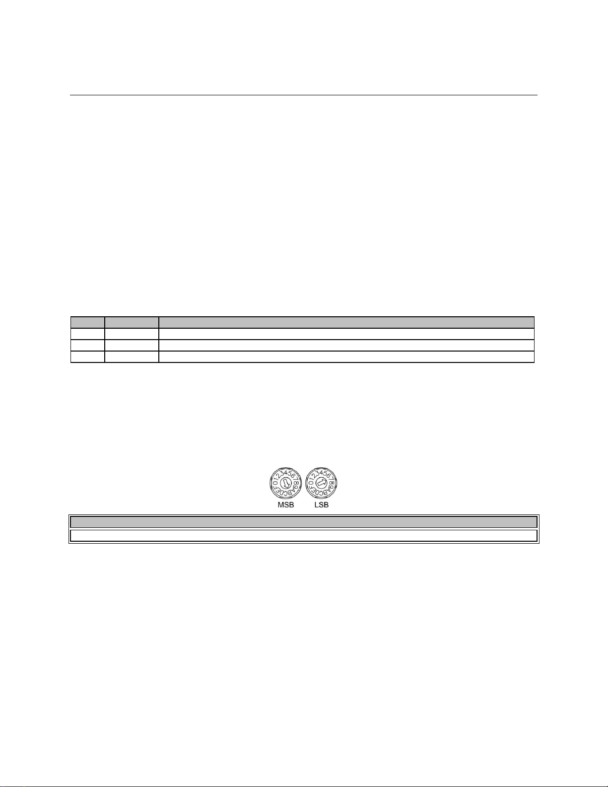
Device ID switches
The rotary ID switches give the unit a unique Device ID. The switches are in hexadecimal format. All units
of the same device type must have a unique Device ID to function properly within a Vocia Paging World.
The Factory Default Device ID is 01. A Device ID of 00 is invalid and cannot be used.
To assign a Device ID of hex 07, leave the MSB switch on 0 and turn the LSB switch to 7. Device ID
switches should be set using a 0.1 inch (2.5mm) to 0.12 inch (3.0mm) flat blade screwdriver.
Input Connectors
Sixteen parallel input connections are provided on the GPIO-1 as well as Isolated Ground and Ground
connections. Under software control the logic level of each input can be set independently to operate one
of three ways.
• TTL: 2V to 5V logic sense. To enable a TTL input, apply a TTL logic high or low with respect to Isolated
Ground. This can be configured in software to detect a low to high or high to low transition.
• High Range: To enable a High Range input, use a dry contact to switch the input to a voltage of 24V
DC with respect to Isolated Ground. This can be configured in software to detect a low to high or high
to low transition.
• High Range – Monitored: This circuit is implemented in the same way as the High Range input. This
option allows monitoring of eachinput for short to ground and open circuit. In order to sense open
Page 5

circuit, a terminating resistor must be fitted between each Input and Isolated Ground at the far end of
NOTE
connected to the VM input.
CAUTION
qualified person as required to conform with all local codes.
the circuit being sensed. The Inputs will sense open circuits on the line between its input and the
terminating resistor. Shorts to Isolated Ground are sensed across the entire line being monitored. A
6k8Ω resistor should be used for each input. If a monitoring fault is detected on any input the logic state
or transitions on that input will be ignored until the fault is cleared. High Range – Monitored inputs
require a low to high transition to enable the input (transition direction not configurable).
Output Connectors
Sixteen parallel outputs are provided on the GPIO-1 as well as Isolated and Chassis Ground connections.
Each output is able to accept either an external positive voltage between 4 and 30V or use the 24V DC
100mA reference voltage provided on the unit. The 24V DC supply for use with the Aux Power port is not
provided with the unit and will need to be sourced locally. Outputs will be monitored for short to ground,
short to supply and if High Range - Monitored is being used, open circuit conditions will be monitored as
well. Consideration should be given to the state of the output when network connectivity is lost. A Voltage
Monitor (VM) input is provided in order that a short to supply reference voltage is incorporated in output
Fault monitoring. A voltage of between 4 - 30V is required by the VM input in order for the outputs to
operate.
If the GPIO-1 Outputs are using a High Range Monitored type of circuit the VM input must match or be
greater than the highest Output Voltage being used. If a higher Voltage is seen on the Outputs compared
to the VM Input a Short to Supply fault will be indicated.
The VM Input must always be connected to the 24V supply on Pin 23 or if an external supply is used the supply voltage should be
Auxiliary Power
The GPIO-1 will be capable of operation from two power supply types - PoE and 24V DC. Any or all
power sources may be connected concurrently. Loss or return of any power source will not result in
interruption to operation. PoE power has priority over 24V DC when both sources are connected. Fault
monitoring of each Power Supply input is enabled by default. The Vocia software allows monitoring to be
enabled or disabled on each power supply.
If PoE Power is to be used an 802.3af Class 3 or 802.3at Type 1, Class 3, compliant PoE switch or midspan adapter is required to either or both Ethernet ports.
When power is present at either or both of the 24V Aux power inputs the adjacent green power LED
indicator will illuminate. When PoE power is present at either or both of the Ethernet ports the adjacent
green power LED indicator will illuminate.
Due to potential energy hazard, connections to the Auxiliary Power DC inputs must be made by a qualified electrician or other
 Loading...