

Vocera Linea Plus AG Installation & Servicing Instructions Manual
Supplied By www.heating spares.co Tel. 0161 620 6677
Plus AG
Installation
& Servicing
Instructions
British Gas Service Listed
G.C. No. 47 094 27 (Linea 24)
G.C. No. 47 094 28 (Linea 28)
G.C. No. 47 094 29 (Linea Plus)
THESE INSTRUCTIONS
TO BE RETAINED
BY USER
Supplied By www.heating spares.co Tel. 0161 620 6677
CONTENTS
Section Subject Page no
Section 1 Introduction 1
General Layout 1
Section Subject Page no
Concluding Operations 20
Section 7 Instructing The User 20
Section 2 Design Principles & Operating
Sequence 2
Schematic Diagram 2
Central Heating Mode 2
Domestic Hot Water Mode 2
Safety Devices 2
Frost Thermosat 2
Section 3 Technical Data 3
Dimensions & Contents 3
Connection Sizes 3
Installation Requirements 3
Electrical Details 3
Performance & Limitations 3
Working Pressure (H/W & C/H) 3
Flow Rates 3
Central Heating Pump Duty 4
Section 4 General Requirements 5
Related Documents 5
Location of Appliance 5
Gas Supply 5
Flue System 5
Air Supply 6
Water Circulation (C/H) 6
Pipework 6
By-Pass 6
System Design 6
Filling Point 8
Electrical Supply 8
Showers 8
Section 5 Installation 9
Delivery 9
Unpacking 9
Preparing For Mounting 9
Mounting The Appliance 10
Fitting The Flue Horizontal - Vertical
Twin 10-11
Connecting Gas & Water Supplies 15
Electrical connections 15
Section 6 Commissioning 17
Gas Installation 17
Initial Flushing of Pipework 17
Initial Filling of System 17
System Design Pressure 17
Checking Electrical supply 17
Lighting The Boiler 17
Checking Burner Pressures 18
Range Rating C/H 19
Checking The Flue System 19
Checking The Heating Thermistor 19
Regulating The C/H System 19
Final Flushing The C/H System 19
Filling & Testing H/W System 19
Final Checks For Operation 20
Section 8 Servicing Instructions 21
General 21
Recommended Routine Servicing 21
Replacement Of Parts 21
To Gain General Access 22
To Remove:
Room Sealed Chamber Front Cover22
Main Burner & Electrode 23
Main Burner Injectors 23
Main Heat Exchanger 23
Fan 24
DAPS
Combustion Chamber Insulation Panel
Ignition PCB 25
Gas Control Valve 25
Pump 26
Domestic Flow Switch 26
Diverter
Domestic Heat Exchanger 27
Diverter Valve 27
Main Expansion Vessel 27
Safety Valve 28
Pressure Switch 28
Motorised Valve 29
Printed Circuit Board 29
Display Printed Circuit Board 29
Safety Thermostat 29
Thermistor Sensors 29
Pressure Gauge 30
Setting Gas Pressures 31
Section 9 Operational Checks & Wiring 32
Sequence of Functions 32
Diagnostic Error Codes 33
Fault Finding Guides 34-43
Section 10Appendix 44
Internal Time Clock Installation 44
External Time Clock Installation 46
S & Y Plan Installations 47
Exploded Diagrams 48-52
Abling & Disabling Controls 53
Functional Flow Diagram 54
Illustrated Wiring Diagram 55
Preliminary Electrical System Checks56
LPG Instructions 57-58
Valve 26
24
24
Supplied By www.heating spares.co Tel. 0161 620 6677
SECTION 1 INTRODUCTION
The Vokèra Linea Plus is a combined central
heating and domestic hot water appliance. By
design it incorporates full sequence electronic
ignition, circulating pump, expansion vessel,
safety valve, temperature gauge, pressure
gauge and 3 port diverter valve. The Plus also
benefits from an air/gas modulation system
and has low NOx emissions.
The boiler is produced as a room sealed
appliance suitable for wall mounting applications only. It is provided with a fan powered
flue outlet with an annular co-axial combustion
air intake which can be rotated through 360
degrees. A vertical & twin flue option is available.
The appliance is designed for use with a sealed
heating system only and is not intended for use
on an open vented system.
The provision of stored domestic hot water is
possible by the addition of an indirect cylinder
with 'S' or 'Y' plan controls.
An automatic range-rating facility is incorporated in the boiler for the central heating system in conjunction with the electronic burner
modulation. The domestic hot water (dhw)
service utilises a motorised control combined
with a 3 port diverter valve to give hot water
priority which also benefits from a preheat
function.
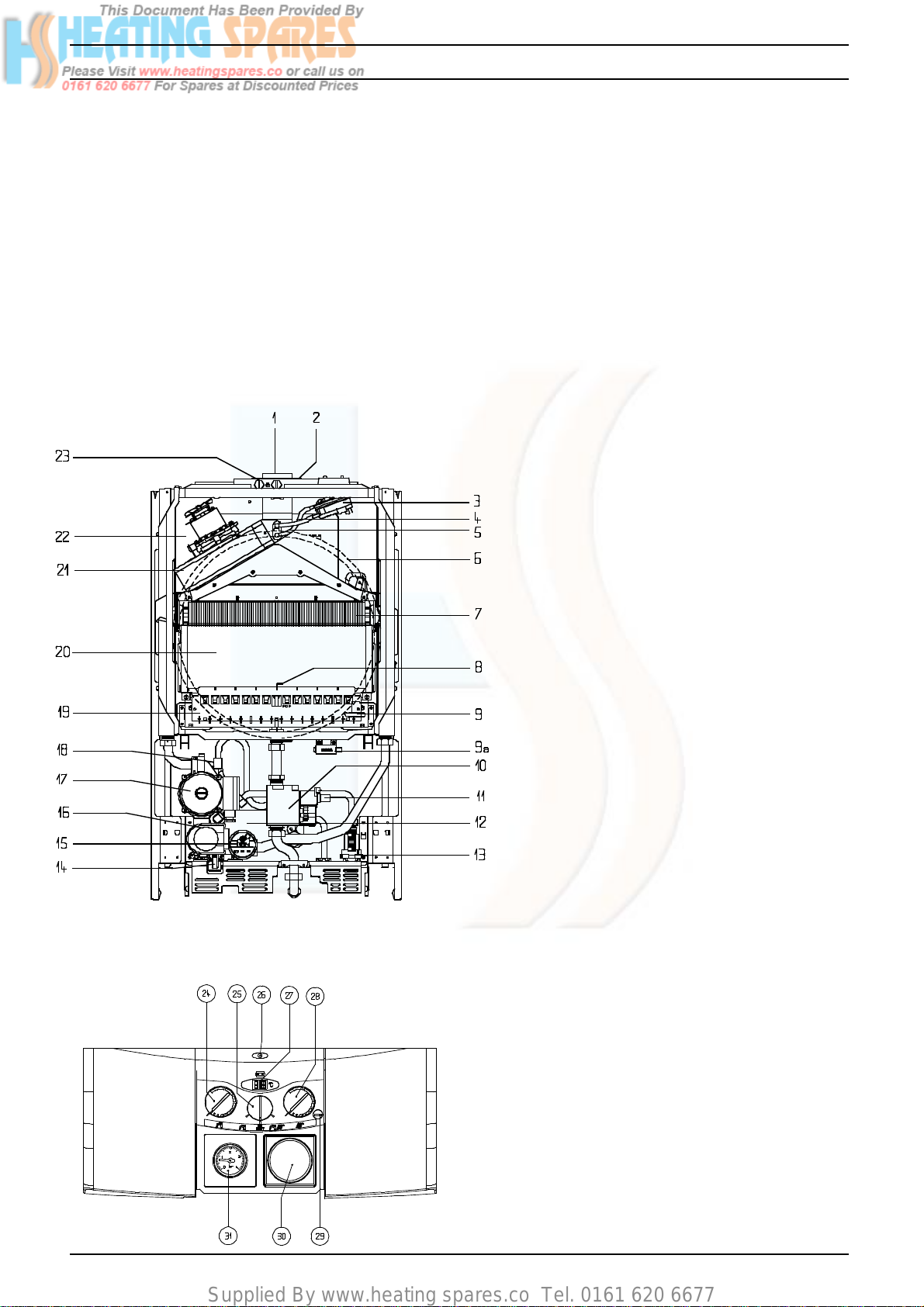
Fig.1 General Layout
1 Flue Outlet
2 Air Intake
3 Differential analog Pressure Switch (DAPS)
4 Silicone Pressure Tube
5 Silicone Negative Pressure Tube
6 Expansion Vessel
7 Main Heat Exchanger
8 Electrode
9 Burner Temperature control
9a Transformer
10 Gas Valve
11 Modulator Coil
12 Domestic Heat Exchanger
13 Domestic Hot Water Flow Switch
14 Safety Valve
15 Pressure Switch
16 Diverter Valve Motor
17 Pump
18 Automatic Air Release Valve
19 Main Burner
20 Combustion Chamber
21 Fan Assembly
22 Air Chamber (with front removed)
23 Flue Gas Analysis Test Point
24 Hot Water Temperature Control
25 Mode Selector Switch
26 Status LED
27 Temperature Indicator
28 Central Heating Temperature Control
29 Combustion Switch
30 Timeclock Aperture (optional)
31 Pressure Gauge
Linea Plus AG
1
Supplied By www.heating spares.co Tel. 0161 620 6677
SECTION 2 DESIGN PRINCIPLES AND OPERATING SEQUENCE
2.1 Fig.1 illustrates the general layout of compo-
nents. Fig.2 illustrates the operating principles
described below.
2.2 Central Heating Mode
2.2.1 When the various switches and controls im-
pose a demand for heat, the pump is started.
If the primary pressure is sufficient, the
electronic circuitry is energised. The fan is
started, the gas valve is energised at an intermediate rate and the electronic ignition goes
through an ignition attempt.
2.2.2 The burner ignition is checked by the electronic
circuitry to ensure correct ignition of the burner;
once successful the gas will flow at 75% of
maximum heat input for a period of
approximately 15 minutes and then go to maximum heat input to maximise heating performance, unless the boiler nears optimum
temperature where it will modulate down to suit
system load.
2.2.3 As water temperature increases this is sensed
by the temperature sensor on the flow pipe
which modulates the fan and burner to match
the heat output to the heat requirement of the
system.
2.2.4 Depending on the load, either a) The water
temperature will continue to rise and the fan
and burner will continue to modulate down;
The burner will switch off at maximum temperature, or b) the water temperature will fall;
the fan and burner
Air Intake
Flue Outlet
3
6
NOTE
Fig. 2
18
17
16
15
A
BCD
7
19
10
12
13
will return to a higher output to match demand.
2.3 Domestic Hot Water Mode
2.3.1 The appliance incorporates a hot water
preheat facility. The appliance will therefore
ignite periodically to maintain heat within the
appliance.
2.3.2 The appliance will operate in domestic hot
water mode whenever the mode selector
switch is on regardless of mode selector
switch position and any demand for central
heating.
2.3.3 The diverter valve will automatically energise
into the hot water position after central heating demand, or will stay in the hot water
position after hot water demand. Opening a
draw off tap will energise the pump and fan
sending primary water to the domestic hot
water heat exchanger.
2.3.4 Temperature control is transferred to the domestic hot water thermostat (potentiometer)
which modulates the fan and burner output
between high and low flame to maintain an
average heat input to suit the dhw output
required.
2.3.5 An overrun is incorporated in the boiler in both
c/h & dhw modes. The fan overruns until the
boiler water cools to approximately 80°C
(176°F).
2.4 Safety Devices
2.4.1 In both central heating and hot water modes
safe operating is ensured by:
A. Differential pressure unit in the primary
circuit which prevents burner operation if water
pressure is too low.
B. An electronic device that checks the primary pressure unit for activation. Failure results in deactivation of the pump, after approximately 10 minutes of operation.
C. A safety thermostat, which interrupts the
control circuit shutting off the gas valve. At the
same time the fan will still operate.
D. A DAPS in the flue system to check the
fan's operation before allowing ignition.
2.4.2 A safety valve is provided to relieve excess
pressure from the primary circuit.
2.4.3 Frost Thermostat
The appliance has a built in frost protection
circuit. Should the boiler temperature sensed
at the primary thermistor fall below 5°C, the
boiler will operate in central heating mode and
continue to operate until the primary thermistor
reaches approximately 40°C.
KEY:
A Central Heating Return.
B Central Heating Flow.
C Hot Water Outlet.
D Cold Water Inlet.
2
NOTE: Pressure switch.
Senses water pressure in the primary circuit
and operates the pressure switch (15)
Linea Plus AG
Supplied By www.heating spares.co Tel. 0161 620 6677
SECTION 3 TECHNICAL DATA
3.1 Units Dimensions and values are given in the
preferred Sl Units with Imperial units in brackets where applicable.
3.2 Dimensions and Contents
Plus AG
Height
Width
Depth
Weight dry
Weight full
820mm (32.3)
500mm (19.7)
355mm (14.0)
48kg (105.6lb)
51kg (112.2lb)
Water content: 3 litres (.66 gals)
for further dimensions see figs 12 - 16
3.3 Connection sizes
Heating flow and return: Nut and olive for
22mm o.d. Cold water inlet: Nut and olive for
15mm o.d. Hot water outlet: Nut and tail for
15mm o.d. Gas Service: Nut and tail for 15mm
o.d. Safety valve outlet: 15mm comp.or capillary
Flue outlet/Air inlet: nom dia 60/100mm specially supplied with boiler (concentric).
Flue outlet/Air inlet: nom dia 80/80mm specially supplied with boiler (twin).
3.4 Installation Requirements
3.4.1 Clearances (Horizontal or Vertical Flue)
Minimum - above casing 225mm (9in) Minimum - below casing 200mm (8in) Minimum In front 600mm (24in) Minimum - At sides
12mm (1/2in) from casing
3.4.2 Maximum heating system contents approx.
76.4 litres (16.8 gals). Acceptance capacity of
expansion vessel 10 litres (2.2 gals).
3.4.3 Means of filling sealed system: to accord with
BS and/or local Water Authority requirements.
3.4.4 The standard concentric horizontal flue allows
a maximum length of duct as follows:
Rear flue: 700mm (wall thickness)
Side flue: 890mm (to centre line of boiler).
Using extension tubes the flue may be extended to the following lengths.
Concentric
Plus AG
Horizontal
Vertical
3.0m
3.0m
Concentric Flue
Reduction in flue
Bend
45°
90°
length for each bend
0.5 m
1.0 m
Twin Flue
Reduction in flue
Bend
45°
90°
length for each bend
1.0 m
1.0 m
3.5 Electrical Details
Mains supply 230v ~ 50Hz Fused 3A
Internal fuse rating F2A and T100mA
Power consumption:160W
3.6 Performance and Limitations Plus AG
Max. input 34.9 kW (119,080 Btu/h)(net h/w)
Max. inpu 38.7 kW (132.050Btu/h)(grossh/w)
Max. input 34.9 kW (119.080 Btu/h)(net c/h)
Max. input 38.7 kW (132.050Btu/h)(gross c/h)
Min. input 9.95 kW (34.052 Btu/h)(net)(c/h)
Min. input 9.95 kW (34.052 Btu/h)(net)(h/w)
Min. input 11.07 kW (37.770 Btu/h)(gross)(c/h)
Min. input 11.07 kW (37.770 Btu/h)(gross)(h/w)
Max. output 32.00 kW (109,200 Btu/h)(h/w)
Max. output 32.00 kW (109,200 Btu/h)(c/h)
Min. output 9.0 kW (30,700 Btu/h)(h/w)
Min. output 9.0 kW (30,700 Btu/h)(c/h)
Central heating output range
Max. 32.0 kW (109,200 Btu/h)
Min. 9.0 kW (30,700 Btu/h)
Nominal hot water production
Temp. rise of 30°C 15.3l/min.
Temp. rise of 35°C 13.1l/min.
Gas Pressures
Max. gas pressure 10.1 mbar h/w
Min. gas pressure 1.1 mbar h/w
Gas Rate
Max. 3.69m3/h 138.8 ft3/h (h/w)
Min. 1.05 m3/h 35.6 ft3/h (h/w)
Note: Use gross input values when gas
rating the appliance
Twin (+ concentric terminal)
Horizontal
Vertical
Plus AG
14/14m
14/14m
3.7 Working Pressure Heating System
3.8 Flow Rates Min. waterflow (dhw) 2.0l/min.
The reduction in flue length for each bend
used is listed opposite.
Linea Plus AG
Burner Details Main burner:
Polidoro type Main burner injectors 16 x 1.35
Maximum 1.5bar/15m w.g./50ft w.g.
Minimum 0.15bar/1.5m w.g./5ft w.g.
Safety valve setting 3bar/30m/102ft w.g.
(0.45 gal/min) Min central heating flow rate
through appliance 350litres/hr (1.28 gal/min)
3
Supplied By www.heating spares.co Tel. 0161 620 6677
3.9 Working Pressure Hot Water System
Maximum 6.0 bar/90psig Minimum 0.6 bar/
7psig
For LPG instructions see page 62.
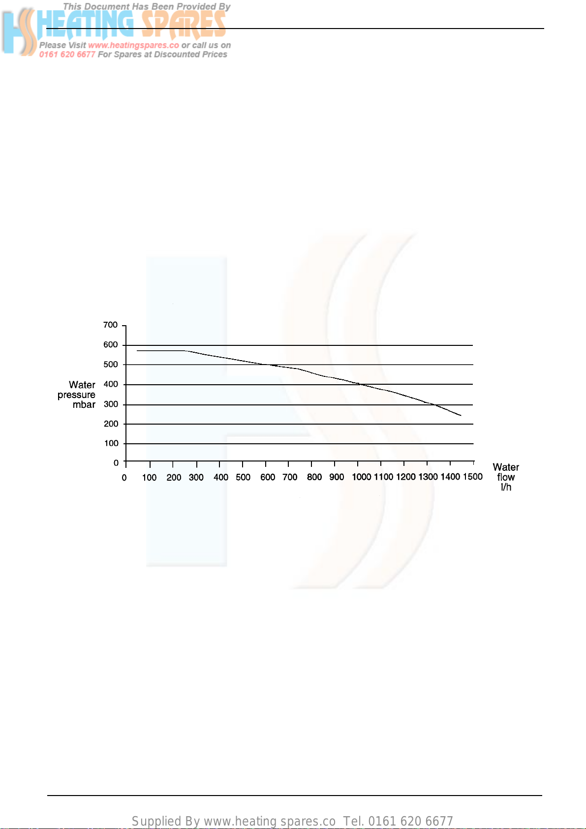
3.10 Central Heating Pump Duty
Fig.3 indicates the flow rate available plotted
against system pressure drop.
N.B. When using this graph apply only the
pressure drop of the system. The curve has
been modified to allow for the pressure drop
through the appliance.
Fig. 3
4
Linea Plus AG
Supplied By www.heating spares.co Tel. 0161 620 6677
SECTION 4 GENERAL REQUIREMENTS
4.0 General Requirements
This appliance must be installed by a competent person in accordance with the Gas Safety
(Installation & Use) Regulations 1998.
4.1 Related Documents
The installation of this boiler must be in accordance with the relevant requirements of
the Gas Safety (Installation & Use) Regulations 1998 the Local Building Regulations, the
current l.E.E. Wiring Regulations, the by-laws
of the local water undertaking, and in Scotland, in accordance with the Building Standards (Scotland) Regulation. In Ireland the local building regulations (IE).
It should be in accordance also with any relevant requirements of the local authority and
the relevant recommendations of the following British Standard Codes of Practice:
BS 6891 1988 Low pressure installation pipes.
BS 6798 1987 Boilers of rated input not exceeding 60kW.
BS 5449 Part 1 1990 Forced circulation hot water systems
BS 5546 1990 Installation of gas hot water supplies for domestic
BS 5440 Part 1 1990 Flues.
BS 5440 Part 2 1989 Flues & Ventilation.
BS 7074 Part 1 1989 Application, selection & installation of expansion
A compartment used to enclose the boiler
must be designed and constructed specifically for this purpose. An existing cupboard or
compartment may be used provided that it is
modified for this purpose.
Details of essential features of cupboard/ compartment design including airing cupboard installations are given in BS 6798:1987. This
appliance is not suitable for external installation.
4.3 Gas Supply
A gas meter is connected to the service pipe
by the gas supplier.
An existing meter should be checked, preferably by the gas supplier, to ensure that the
meter is adequate to deal with the rate of gas
supply required for all appliances it serves.
purposes (2nd family gases).
vessels & ancillary equipment for sealed water
systems.
4.2 Location of Appliance
The combination boiler may be installed in any
room or internal space, although particular
attention is drawn to the requirements of the
current l.E.E. Wiring Regulations, and in Scotland, the electrical provisions of the Building
Regulations applicable in Scotland, with respect to the installation of the combination
boiler in a room or internal space containing a
bath or shower.
Where a room-sealed appliance is installed in
a room containing a bath or shower, any
electrical switch or appliance control, utilising
mains electricity, should be located in such a
position that it cannot be touched by a person
using the bath or shower.
The location chosen for the boiler must permit
the provision of a satisfactory flue and termination. The location must also permit an adequate air supply for combustion purposes
and an adequate space for servicing and air
circulation around the boiler.
Where the installation of the boiler will be in an
unusual location special procedures may be
necessary and BS 6798:1987 gives detailed
guidance on this aspect.
Installation pipes should be fitted in accordance with BS 6891:1988.
Pipework from the meter to the boiler must be
of adequate size. Pipes of a smaller size than
the boiler inlet connection should not be used.
The complete installation must be tested for
soundness as described in the above code.
N.B. If the gas supply for the boiler serves
other appliances ensure that an adequate
supply is available both to the boiler and the
other appliance when they are in use at the
same time.
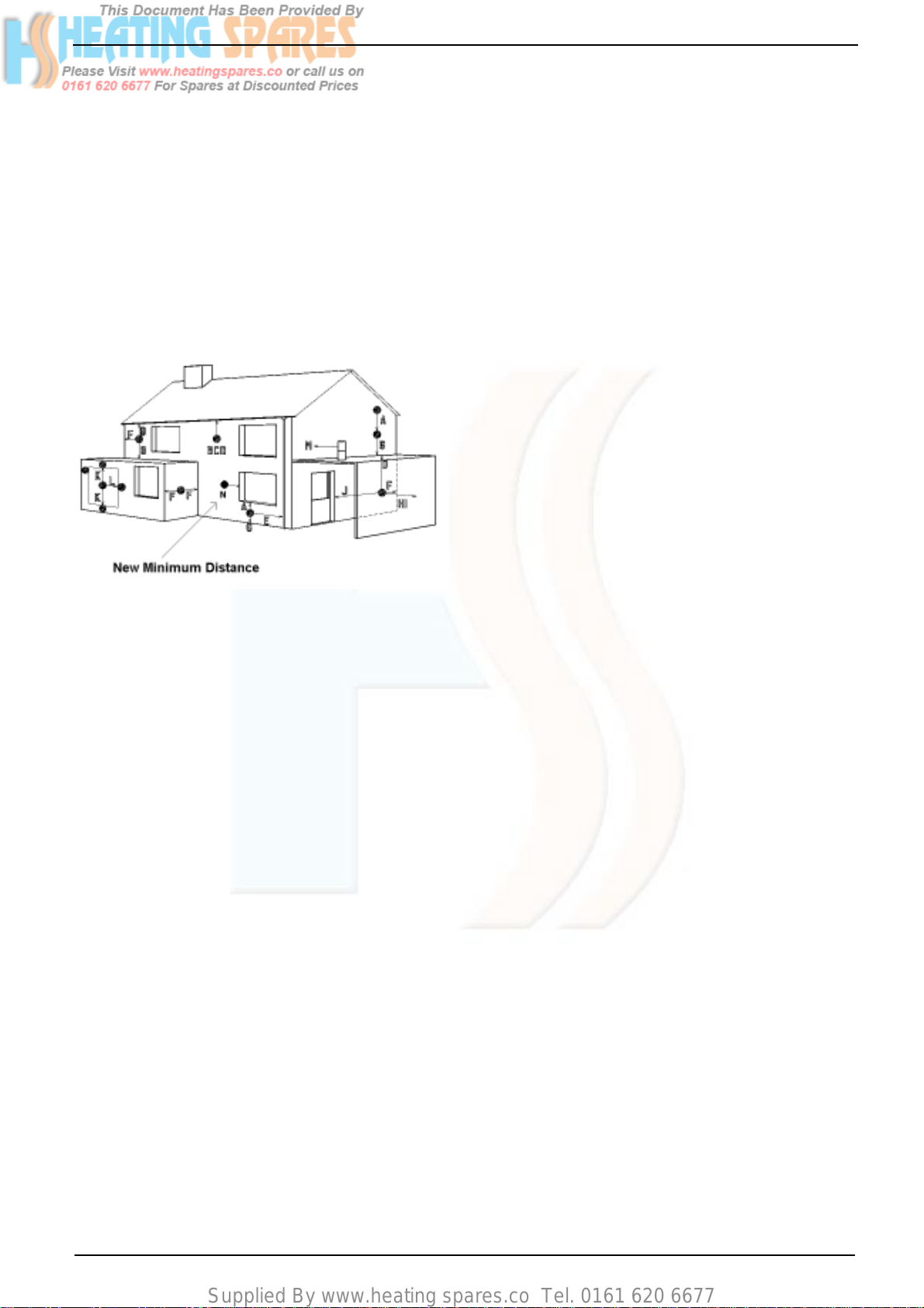
4.4 Flue System
The terminal should be located where dispersal of combustion products is not impeded and
with due regard for the damage or discoloration that might occur to building products in the
vicinity (see fig 4).
The terminal must not be located in a place
where it is likely to cause a nuisance.
In cold and/or humid weather water vapour
may condense on leaving the flue terminal.
The effect of such ‘steaming’ must be considered.
Linea Plus AG
5
Supplied By www.heating spares.co Tel. 0161 620 6677
For protection of combustibles, refer to BS
5440:1 where the terminal is less than 2m
(6.6ft) above a pavement or platform to which
people have access (including any balcony or
flat roof the terminal must be protected by a
guard of durable material).
A suitable guard is available from Vokera Ltd.
Part No 018, G.C. No. 301 106
This guard must be fitted centrally over the
terminal. Mark the positions of the fixings, drill
the wall and secure using wall plugs and 3 of
1˚" No.8 plated screws.
Fig. 4
Terminal position for fan assisted boiler
(minimum distance) mm
A - Directly below an open window or other 300
opening (e.g. air brick)
B - Below gutters, soil pipes or drain pipes 25
C - Below eaves 25
D - Below balconies or car port roof 25
E - From vertical drain pipes and soil pipes 75
F - From internal or external corners 25
G - Above ground or below balcony level 300
H - From a surface facing a terminal 600
I - From a terminal facing a terminal 1200
J - From an opening in the car port (e.g. door
window) into dwelling. 1200
K - Vertically from a terminal on the same wall 1500
L - Horizontally from a terminal on the same wall 300
M - Horizontally from a vertical terminal to a wall 300
N - Horizontally from an opening, airbrick, openable
window, etc. 300
4.6 Water Circulation (Central Heating)
Detailed recommendations are given in S6798:
1987 and BS 5449: 1: 1990 (for smallbore and
microbore central heating systems).
4.6.1 The following notes are given for general
guidance.
4.6.2 Pipework
Copper tubing to BS 2871:1:1971 is recommended for water pipe. Jointing should be
either by capillary soldered or with compression fittings.
Where possible, pipes should have a gradient
to ensure air is carried naturally to air release
points and water flows naturally to drain taps.
It should be ensured as far as possible that the
appliance heat exchanger is not a natural
collecting point for air.
Except where providing useful heat, pipes
should be insulated to prevent heat loss and to
avoid freezing. Particular attention should be
paid to pipes passing through ventilated spaces
in roofs and under floors.
4.6.3 By-Pass
An automatic by-pass is incorporated in the
boiler, but systems should be designed to
ensure that with all radiators turned off a flow
rate of at least 350 litres/hour (1.28 gals/min)
is achieved through the system. See 6.9.4.
4.6.4 System Design
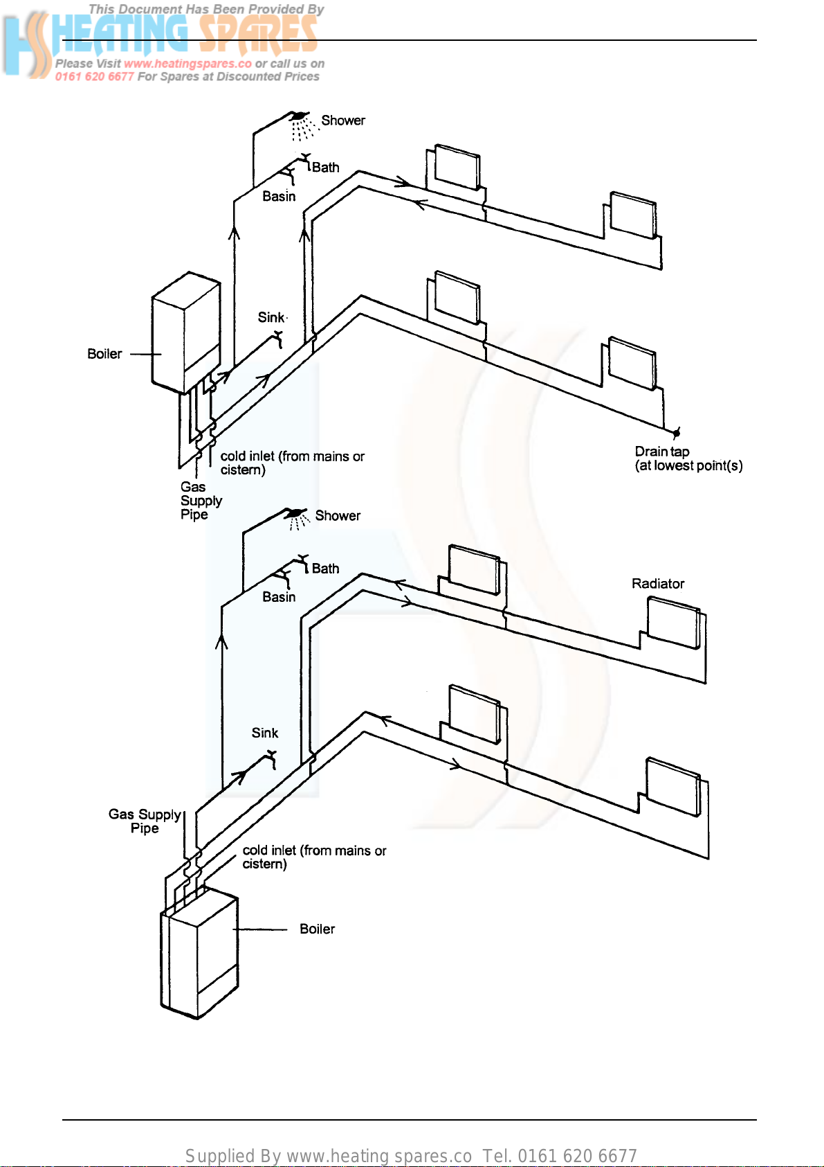
Figs 5 & 5a illustrates typical system layouts
showing options of either, pipe connection
from below as fig. 5, or pipe connection from
above utilising the purpose made duct in the
rear frame of the appliance.
4.6.5 Draining Taps
These must be located in accessible positions
to permit the draining of the whole system. The
taps must be at least 15mm nominal size and
manufactured in accordance with BS 2879:
1980.
NOTE: The flue must be terminated in a place not likely
to cause a nuisance.
4.5 Air Supply
The following notes are intended for general
guidance.
The room sealed fan flued boiler does not
require a permanent air vent for combustion
air supply.
Where installed in a cupboard or compartment
ventilation is not required.
6
Linea Plus AG
Supplied By www.heating spares.co Tel. 0161 620 6677
Fig. 5
Fig. 5a
N.B. Vokèra Ltd recommend a 2-pipe system. Single pipe systems are more liable to be troublesome unless
carefullly designed and installed.
Linea Plus AG
7
Supplied By www.heating spares.co Tel. 0161 620 6677
4.6.6 Air Release Points
These must be fitted at all high points where
air will naturally collect, and must be sited to
facilitate complete filling of the system.
4.6.7 The appliance has an integral sealed expansion vessel to accommodate the increase of
water volume when the system is heated. It
can accept up to 10 litres of expansion water.
If the appliance is connected to a system with
an unusually high water content. Calculate the
total expansion and add additional sealed
expansion capacity as appropriate.
In general, modern systems will present no
problem.
4.6.8 Filling Point
A method for filling the system and replacing
water lost during servicing is provided on the
appliance.
This method complies with the Water Supply
(Water Fittings) Regulations 1999.
4.7 Electrical Supply
The appliance is supplied for operation on
230V ~ 50Hz electricity supply. It should be
protected with a 3-amp fuse.
THIS APPLIANCE MUST BE EARTHED.
The method of connection to the mains elec-
tricity must allow complete isolation from the
supply.
The preferred method is by using a fused
double pole switch with a contact separation
of at least 3mm.
The switch must supply ONLY the appliance
and immediate electrical control circuits (e.g.
programmer / room thermostat)
Alternatively, use an unswitched shuttered
socket outlet with a fused 3-pin plug both
complying with BS 1363.
4.8 Showers
If a shower control is to be supplied from the
combination unit it should be of the type which
incorporates a thermostatic control and by
design is suitable for use with a combination
boiler. Check application with shower manufacturer.
C/H Flow
Valve
C/H Return
Valve
Safety valve
outlet
Filling Loop
Cold water
Inlet Stopcock/
filling valve
Gas
Cock
Hot water
Outlet
Fig.6
Fig. 7
8
Linea Plus AG
Supplied By www.heating spares.co Tel. 0161 620 6677
SECTION 5 INSTALLATION
Fig. 8
Fig. 9
5.1 Delivery (fig. 8)
The appliance is delivered in a heavy duty
cardboard carton.
Lay the carton on the floor with the writing the
correct way up.
5.2 Unpacking (fig. 9)
Pull both sides of the top of the carton open.
Do not use a knife. Remove the hanging
bracket, literature pack and fittings pack, from
the packaging. Remove the package supports.
Lift the appliance from the carton and lay the
appliance down with the white frame on the
floor.
Remove the protective bag, and the
polystyrene support from the back of the
appliance.
Do not remove the insulation jacket on the
domestic heat exchanger.
The fittings pack contains
Wiring harness for optional built in timer
15mm nut & olive
Adjustable stopcock
Safety valve outlet pipe (1)
Filling loop hose (1)
Various washers
Flue kit supplied in separate carton.
5.3 Preparing for Mounting
5.3.1 Push to release front door panel and lower to
reveal controls. Loosen the 2 captive screws
securing the front control panel to the lower
part of the casing and lower to reveal inside of
boiler (fig. 10).
5.3.2 Remove two screws at base of casing, slightly
lift the casing and slide it gently towards the
top of the appliance to disengage the case
from the top suspension hooks (fig. 11).
5.3.3 Ensure the casing and screws are put to one
side in a safe place.
Fig. 10
Fig. 11
Case Screws
Linea Plus AG
Case screws
(one either side)
9
Supplied By www.heating spares.co Tel. 0161 620 6677
5.4 Mounting the appliance
The appliance should be mounted on a smooth,
vertical surface, which must be capable of
supporting the full weight of the appliance. Care
should be exercised when determining the
position of the appliance with respect to hidden
obstructions such as pipes, cables, etc.
When the position of the appliance has been
decided – using the template supplied – carefully
mark the position of the fixing jig/mounting
bracket assembly (see fig. 7) and flue-hole (if
applicable).
5.4.1 Important
There are two holes on the template. The
lower hole should be used with the telescopic
flue kit (part no. 0225705 & 0225710). The
upper hole is for use with all other horizontal
flue kits.
5.4.2 Maximum flue lengths
Flue system Linea Plus AG
Concentric Horizontal 3.0m
Concentric Vertical 3.0 m
Twin flue 14m/14m + terminal
5.5 Fitting the flue
The top flue outlet permits both horizontal and
vertical flue applications to be considered,
alternatively, the Vokera twin flue system can
be utilised if longer flue runs are required.
5.5.1 Concentric horizontal flue
(For concentric vertical flue, see 5.5.2)
(For twin flue applications, see 5.5.3)
The appliance flue outlet elbow can be rotated
through 360º on its vertical axis. In addition the
flue may be extended from the outlet elbow in
the horizontal plane (see 5.4.2), however if the
flue is to be extended or additional bends are to
be fitted, the standard horizontal flue kit (part no.
2359029) must be used. A reduction must also
be made to the maximum length (see table)
when additional bends are used.
Horizontal flue terminals and accessories
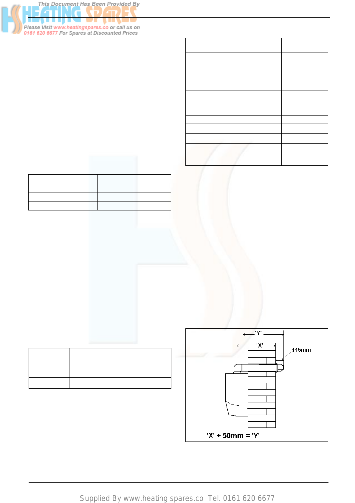
Part No. Description Min-Max Length
0225705 Standard telescopic flue 380mm – 600mm
(Dimension ‘X’)
0225710 Extended telescopic flue 600mm – 920mm
(Dimension ‘X’)
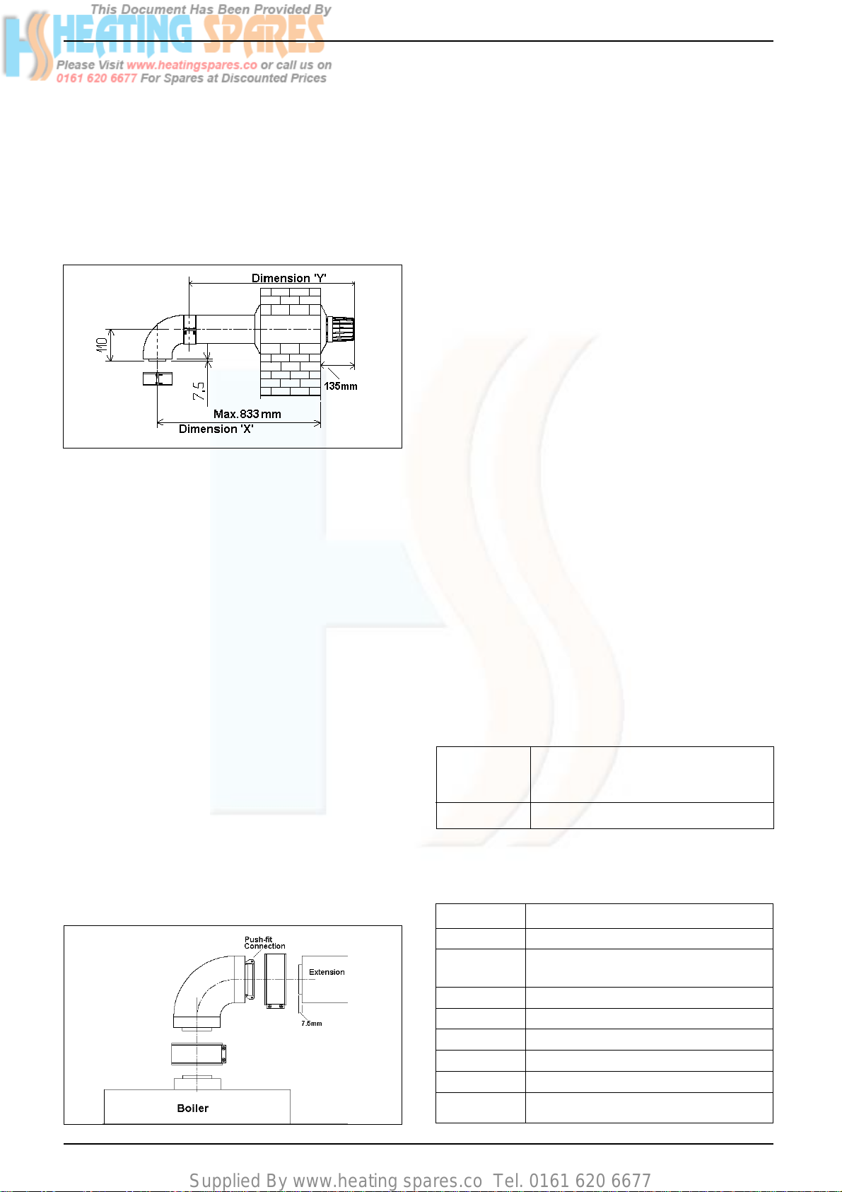
2359029 Horizontal flue kit 833mm
For use with add. (Dimension ‘X’)
Bends & extensions
2359069 750mm extension 750mm
2359079 1500mm extension 1500mm
2359049 45º bend (pair) N/A
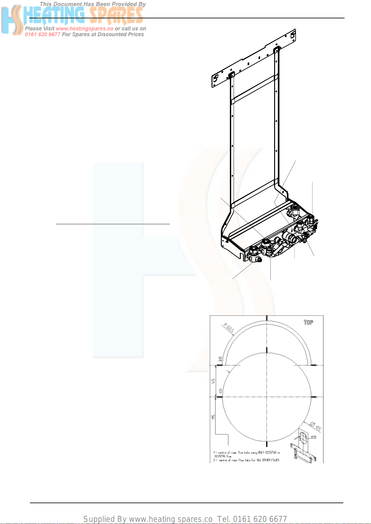
2359059 90º bend N/A
0225760 Wall bracket (5) N/A
FITTING THE TELESCOPIC FLUE KIT (0225705 &
0225710)
Carefully measure the distance from the centre of the
appliance flue outlet to the face of the outside wall
(dimension ‘X’ see fig. 12). Add 50mm to dimension ‘X’
to give the overall flue length (dimension ‘Y’). Using the
complete telescopic flue assembly adjust the length to
suit dimension ‘Y’. Once the telescopic flue terminal has
been adjusted to the correct length, secure the flue
assembly with the screw supplied.
Insert the flue assembly into the previously drilled flue
hole and locate the flue bend over the appliance flue
outlet. Push the flue bend down over the appliance flue
outlet and ensure the correct seal is made. Pull the flue
assembly towards and over the flue bend – using a
twisting action – ensuring the correct seal is made.
Check that the terminal protrudes past the finished
outside wall by the correct length (115mm).
NOTE
You must ensure that the entire flue system is properly
supported and conncented.
Reduction for bends
Bend Reduction in maximum flue length
for each bend
45º bend 0.5 metre
90º bend 1.0 metre
Using the template provided (see 5.4.1), mark
and drill a 125mm hole for the passage of the
flue pipe. The hole should have a 1º drop from
the boiler to outside, to eliminate the possibility
of rainwater entering the appliance via the flue.
The fixing holes for the wall-mounting bracket &
jig should now be drilled and plugged, an
appropriate type and quantity of fixing should
be used to ensure that the bracket is mounted
securely. Once the bracket & jig has been
secured to the wall, mount the appliance onto
Seal the flue assembly to the wall using cement or a
suitable alternative that will provide satisfactory
weatherproofing. The interior and exterior trim can now
be fitted.
the bracket.
10
Fig. 12
Linea Plus AG
Supplied By www.heating spares.co Tel. 0161 620 6677
FITTING THE STANDARD (2359029)
HORIZONTAL FLUE KIT (see 5.4.1)
Carefully measure the distance from the centre
of the appliance flue outlet to the face of the
outside wall (dimension ‘X’ see fig. 13). Ensure
the inner (60mm) pipe is fully inserted into the
outer (100mm) pipe (when the inner pipe is
fully inserted, it stands proud of the outer pipe
by 7.5mm). Add 32mm to dimension ‘X’ to give
the overall flue lenghth (dimension 'Y')standard
horizontal flue kit (part no. 2359029) is suitable
for a distance (dimension ‘Y’) of up to 865mm.
Fig. 13
NOTE
Dimension ‘Y’ is measured from the end of the
terminal to the end of the outer (100mm) pipe.
The internal trim should be fitted to the flue
pipe before connection of the 90º bend.
If the horizontal flue kit (2359029) requires to
be cut to the correct size (dimension ‘Y’), you
must ensure that the inner (60mm) pipe stands
proud of the outer (100mm) pipe by 7.5mm
(see fig. 13A). Ensure any burrs are filed or
removed and that any seals are located
properly before assembly.
Connect the inner (60mm) pipe of the terminal
assembly to the push-fit end of the 90º bend
(supplied) using a twisting action. Insert the
assembled flue into the previously drilled hole.
Using the clips & screws supplied, connect the
flue assembly to the boiler, ensuring that the
terminal protrudes past the finished outside
wall by the correct length (135mm).
You must ensure that the entire flue system is
properly supported and connected.
EXTENDING THE HORIZONTAL FLUE
If the horizontal flue requires extension/s or
additional bend/s, the horizontal flue terminal
kit (2359029) must be used. Connect the bend
– supplied with the terminal kit – to the top of the
boiler using the clips, screws, & gaskets
supplied. The additional bends & extensions
have an internal push-fit connection, care should
be taken to ensure that the correct seal is made
when assembling the flue system. Connect the
required number of flue extensions or bends
(up to the maximum equivalent flue length) to
the flue terminal using the clips, screws, &
gaskets supplied (see fig. 13 & 13A).
NOTE
When cutting the horizontal flue terminal or an
extension to the required length, you must
ensure that the excess is cut from the plain end
of the terminal or extension, and that the inner
(60mm) pipe is 7.5mm longer than outer
(100mm) pipe (see fig. 13 & 13A). Remove any
burrs, and check that any seals are located
properly.
You must ensure that the entire flue system is
properly supported and connected.
Seal the flue assembly to the wall using cement
or a suitable alternative that will provide
satisfactory weatherproofing. The interior and
exterior trim can now be fitted.
5.5.2 CONCENTRIC VERTICAL FLUE
The vertical flue terminal can be connected
directly to the appliance flue outlet. Alternatively,
an extension or bend can be connected to the
appliance flue outlet if desired (see 5.4.2),
however if additional bends are fitted, a reduction
must be made to the maximum flue length (see
table below).
Reduction for bends
Bend Reduction in maximum flue length for
each bend
45º bend 0.5 metre
90º bend 1.0 metre
Seal the flue assembly to the wall using cement
or a suitable alternative that will provide
satisfactory weatherproofing. The exterior trim
Vertical flue terminal and accessories
can now be fitted.
Fig. 13A
Linea Plus AG
Part No. Description Length
2359039 Vertical flue terminal 1.0 metre
0225770 Pitched roof flashing N/A
plate
0225765 Flat roof flashing plate N/A
2359069 750mm extension 750mm
2359079 1500mm extension 1500mm
2359049 45º bend (pair) N/A
2359059 90º bend N/A
0225760 Wall bracket (5) N/A
11
Supplied By www.heating spares.co Tel. 0161 620 6677
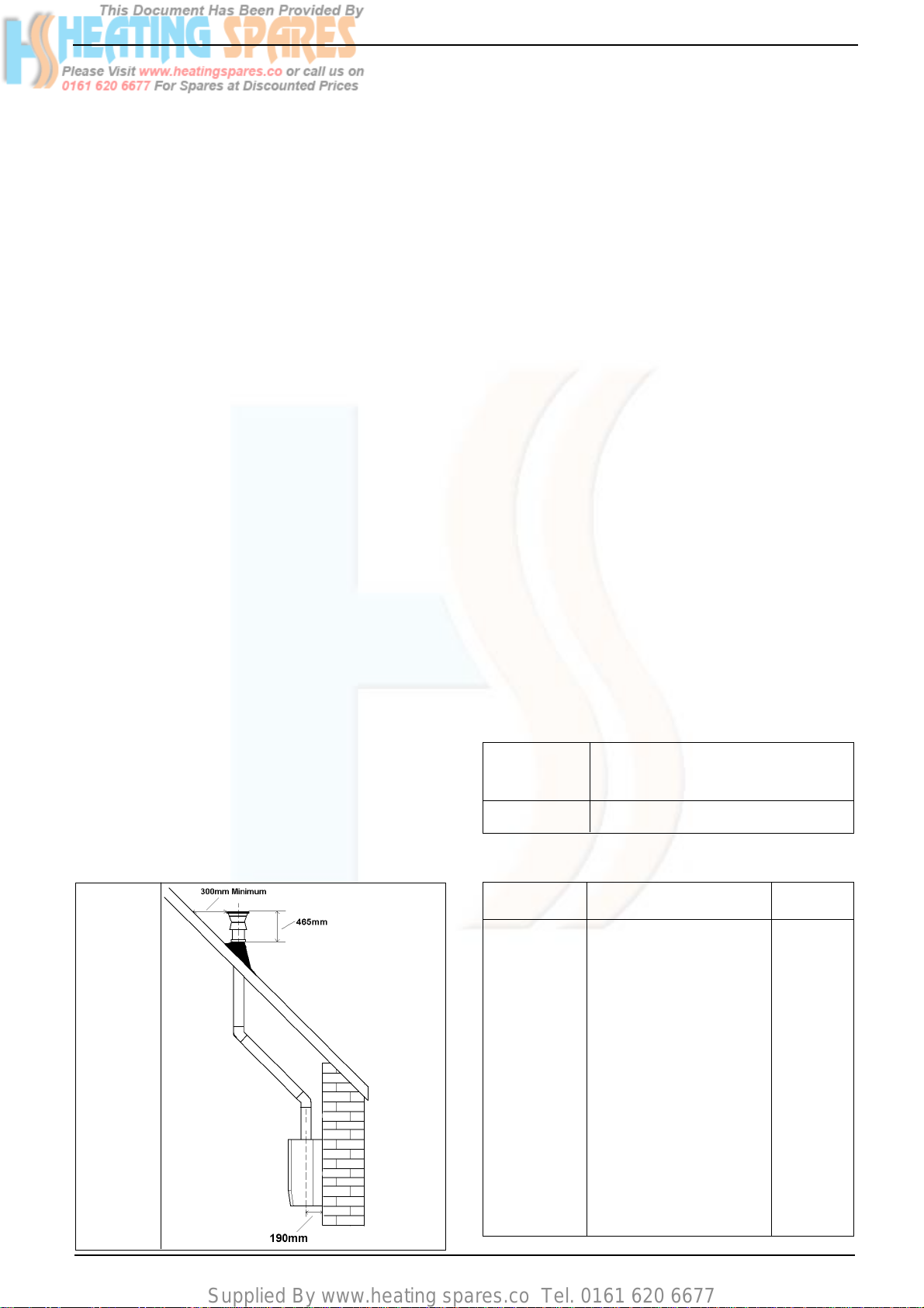
Using the dimensions given in fig. 14 as a reference,
mark and cut a 105mm hole in the ceiling and/or
roof.
Fit the appropriate flashing plate to the roof and
insert the vertical flue terminal through the flashing
plate from the outside, ensuring that the collar on
the flue terminal fits over the flashing.
The fixing holes for the wall-mounting bracket & jig
should now be drilled and plugged, an appropriate
type and quantity of fixing should be used to ensure
that the bracket is mounted securely. Once the
bracket has been secured to the wall, mount the
appliance onto the bracket & jig.
IMPORTANT
The vertical flue terminal is 1.0 metre in length and
cannot be cut; therefore it may be necessary to
adjust the height of the appliance to suit or use a
suitable extension.
Remove or discard the flue restrictor ring from the
appliance flue outlet (see fig. 1), if the total flue
length – including the allowance for any additional
bends – exceeds 1.0 metre.
Connect the vertical flue assembly to the boiler flue
spigot using the 60mm & 100mm clips, gaskets, &
screws (supplied), ensuring the correct seal is
made. The flue support bracket (supplied with the
vertical flue kit) can now be fitted.
If the vertical flue requires extension/s or additional
bend/s, connect the required number of flue
extensions or bends (up to the maximum equivalent
flue length) between the boiler and vertical flue
assembly (see fig. 13A).
5.5.3 TWIN FLUE SYSTEM
The Vokera twin flue system enables greater
flue distances to be achieved (see 5.4.2) than
that of the standard concentric flue system. It
can be used for horizontal or vertical
applications, however the twin flue system
must be converted to the dedicated concentric
flue kit for termination. It is essential that the
installation of the twin flue system be carried
out in strict accordance with these instructions.
GUIDANCE NOTES ON TWIN FLUE
INSTALLATION
• The flue must have a fall back of 1º back to
the appliance to allow any condensate that
may form in the flue system to drain via the
condensate drain. Consideration must also
be given to the fact that there is the possibility
of a small amount of condensate dripping
from the terminal.
• Ensure that the entire flue system is
adequately supported, use at least one
bracket for each extension.
• The entire flue system must be adequately
insulated to maintain heat within the flue
system thereby reducing the possibility of
condensate production.
As the exhaust outlet pipe can reach very high
temperatures it must be protected to prevent
persons touching the hot surface.
NOTE
When cutting an extension to the required length,
you must ensure that the excess is cut from the
plain end of the extension and that the inner (60mm)
pipe is 7.5mm longer than outer (100mm) pipe (see
fig. 13A). Remove any burrs, and check that any
seals are located properly.
You must ensure that the entire flue system is
properly supported and connected.
Fig. 14
Reduction for bend
Bend Reduction in maximum flue length for
each bend
45º bend 1.0 metre
90º bend 1.0 metre
Twin flue accessories
Part No. Description Length
0225805 Horizontal flue terminal 1.0 metre
0225810 Vertical flue terminal 1.0 metre
300 Twin adapter kit N/A
0225770 Pitched roof flashing plate N/A
0225765 Flat roof flashing plate N/A
0225815 Condensate drain kit N/A
0225820 0.25m extension (pair) 250mm
0225825 0.5m extension (pair) 500mm
0225830 1.0m extension (pair) 1000mm
0225835 2.0m extension (pair) 2000mm
0225840 45º bend (pair) N/A
0225845 90º bend (pair) N/A
0225850 Twin bracket (5) N/A
0225855 Single bracket (5) N/A
12
Linea Plus AG
Supplied By www.heating spares.co Tel. 0161 620 6677
Mounting the boiler
The fixing holes for the wall-mounting bracket
& jig should now be drilled and plugged, an
appropriate type and quantity of fixing should
be used to ensure that the bracket is mounted
securely. Once the bracket has been secured
to the wall, mount the appliance onto the
bracket & jig.
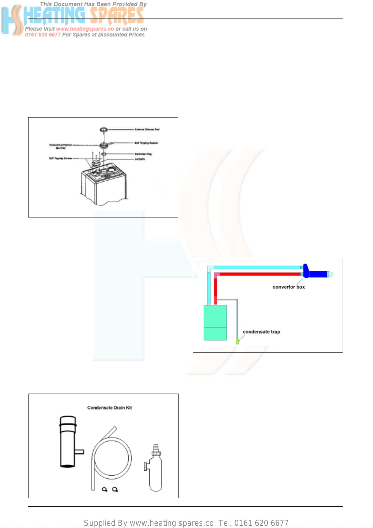
5.5.3.1 Installation of twin adaptor kit (fig. 15)
The condensate drain kit must be fitted within
1 metre of the appliance flue outlet. It is
recommended that the condensate drain kit
should be fitted in the vertical plane, however
it can be fitted horizontally with care.
• Fit the first bend to the condensate drain kit
or exhaust connection manifold by firmly
pushing in to position.
• Using the two holes in the exhaust connection
manifold as a guide, drill a 3mm hole in each
and secure using the screws provided.
• Connect the air inlet pipe to the air baffle as
above.
• The twin flue pipes extensions and
accessories can now be installed by pushing
together (the plain end of each extension or
bend should be pushed approximately 50mm
into the female socket of the previous piece).
The condensate drain trap must be connected
to the drain in accordance with Building
Regulations or other rules in force
Fig. 15
5.5.3.2
• Remove or discard the flue restrictor ring
from the appliance flue outlet (see fig. 1).
• Insert the small restrictor ring (supplied with
the twin adapter kit) if the total flue length –
including the allowance for any bends – is
less than 8 metres.
• Insert the exhaust connection manifold onto
the appliance flue outlet.
• Place the silicone seal (supplied with twin
adapter kit) over the rim of the exhaust
connection manifold.
• Remove one of the blanking plates (located
to the left & right of the appliance flu
• Remove one of the blanking plates (located
to the left & right of the appliance flue outlet)
and – using the same screws – install the air
baffle.
Installation of condensate drain kit
(fig. 16)
5.5.3.3 Horizontal termination ( fig. 17)
The twin flue system must be converted to the
dedicated concentric flue kit for termination.
• The horizontal terminal is supplied with a
built-in converter box and cannot be
shortened.
Fig. 17
• A 130mm hole is required for the passage of
the concentric terminal through the wall.
Depending on site conditions it may be
preferable to install the terminal assembly
prior to fitting the twin flue pipes.
Fig. 16
Linea Plus AG
Mark and drill a 130mm hole for the passage
of the horizontal flue terminal, ensuring that
there is a 1º fall back to the boiler (17mm per
1000mm). Insert the terminal assembly into
the flue hole.
Push-fit the twin flue pipes onto the concentric
to twin converter ensuring that the exhaust
pipe connects to the exhaust connection on
the concentric to twin converter.
If necessary cut the plain ends (male) of the
twin flue pipes to allow connection to the
concentric to twin converter.
13

Supplied By www.heating spares.co Tel. 0161 620 6677
NOTE
• Before cutting twin flue pipes ensure
allowances have been made for connection
onto the previous piece and onto the
concentric to twin converter. The last twin
flue pipes must be pushed 50mm onto the
male spigots of the concentric to twin
converter.
NOTE
You must ensure that the entire flue system is
properly supported and connected.
When cutting an extension to the required
length, you should ensure that the excess is
cut from the plain end of the extension. Remove
any burrs, and check that both seals are
located properly.
Seal the flue terminal assembly to the wall
using cement or a suitable alternative that will
provide satisfactory weatherproofing. The
interior and exterior trim can now be fitted.
5.5.3.4 Vertical termination (See fig. 18)
The twin flue system must be converted to the
dedicated concentric flue kit for termination.
• The vertical terminal is supplied with a builtin converter box and cannot be shortened.
• A 130mm hole is required for the passage of
the concentric terminal through the ceiling
and/or roof.
Depending on site conditions it may be
preferable to install the terminal assembly
prior to fitting the twin flue pipes.
Fit the appropriate flashing plate to the roof
and insert the vertical flue terminal through the
flashing plate from the outside, ensuring that
the collar on the flue terminal fits over the
flashing.
Push-fit the twin flue pipes onto the concentric
to twin converter ensuring that the exhaust
pipe connects to the exhaust connection on
the concentric to twin converter.
If necessary cut the plain ends (male) of the
twin flue pipes to allow connection to the
concentric to twin converter.
Fig. 18
• You must ensure that the entire flue system
is properly supported and connected.
• Ensure that any horizontal sections of pipe
have a 1º fall towards the appliance (17mm
per 1000mm).
• The convertor box on the vertical terminal
will have to be temporarily removed when
inserting the terminal through the flashing.
• The condensate trap must be primed with
water prior to commissioning the boiler.
• The condensate drain trap must be
connected to the drain in accordance with
building regulations or other rules in force.
NOTE
• Before cutting twin flue pipes ensure
allowances have been made for connection
onto the previous piece and onto the concentric
to twin converter. The last twin flue pipes must
be pushed 50mm onto the male spigots of the
concentric to twin converter.
14
Linea Plus AG
Supplied By www.heating spares.co Tel. 0161 620 6677
5.6 Connecting the Gas and Water
5.6.1 Figs. 6 and 15 show the locations of the
fittings.
5.6.2 Do not over tighten nuts, use another spanner
to apply counter force to avoid damaging the
appliance
5.6.3 Gas Supply
Connecting the gas supply.
Connect a 15mm gas pipe to the gas service
tap and tighten the union nut securing the tap
to the appliance.
Pipework from the meter to the appliance
must be of adequate size.
A minimum gas pressure of 20mb (8 in. w.g.)
must be available at the appliance inlet at full
flow rate. See section 3.
DO NOT use pipes of a smaller size than the
appliance inlet connection.
5.6.4 Central Heating
Connect the central heating pipework (22mm
o.d) to the respective valves, right hand: flow,
left hand: return, and tighten the nuts.
5.6.5 Hot Water
Connect a 15mm pipe to the hot water outlet
connection of the appliance. Tighten the nut.
If the hot water system does not include a tap
below the hot water outlet connection, provide
a suitable drain tap to permit draining of the
appliance hot water side during servicing.
5.6.6 Cold Water
Connect a 15mm cold water service pipe to
the inlet stopcock of the appliance. Tighten the
nut.
If the cold water supply is liable to high pressure or large pressure fluctuations, a flow/
pressure regulator should be fitted in the supply pipe.
Should the appliance be subject to 'mains
knock' it would be advisable to install an non
return valve in the hot water outlet pipe to
prevent unnecessary activation of the domestic flow switch.
5.6.7 Safety Valve Discharge
Connect a 15mm pipe to the discharge outlet
of the appliance.
The discharge should terminate facing downwards outside the building in a position where
discharging (possibly boiling) water will not
create danger or nuisance; but in an easily
visible position.
5.7 Electrical Connections
5.7.1 The electricity supply must be as specified in
4.7. If controls external to the appliance are
required, design of the external electrical circuits should be undertaken by a competent
person.
See Section 10 for further advice.
N.B. IT IS ESSENTIAL THAT ALL EXTERNAL CONTROL CIRCUITS AND WIRING IS
WIRED FROM THE SAME ELECTRICAL ISOLATOR AS SERVES THE APPLIANCE.
Factory fitted internal wiring must not be disturbed when wiring external controls.
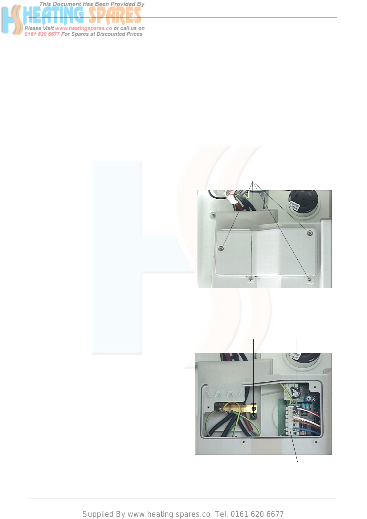
5.7.2 To gain access to the electrical terminals
Remove electrical cover by releasing four
securing screws. Fig.18.
The mains input terminal block is now easily
visible (see fig. 18a).
5.7.3 The electricity supply cable from the isolator
and the appliance terminal block must be 3
core flexible sized 0.75mm˝ (24 x 0.2mm) to
BS6500.
Wiring to the appliance should be rated for
operation in contact with surfaces up to 90°C.
Electrical Cover
Screws
Fig. 18
Factory Fitted
Earth
Screw
Fig. 18a
Link Between
= & TA
Mains Input and
External Controls Terminal
Block
Linea Plus AG
15
Supplied By www.heating spares.co Tel. 0161 620 6677
5.7.4 Pass the cable through one of the cord anchorage points and connect the wires Brown
to L, Blue to N, and Green/Yellow to .
Arrange the cable so that should the cable slip
the anchorage the current carrying conductors become taut before the earthing conductor.
5.7.5 Securely tighten all terminal screws and arrange the cable with slack between the cable
anchor and the terminal block. Tighten the
cord anchorage screw until the cable is secure.
5.7.6 Neatly arrange the external cable in such a
way that unrestricted opening of the controls
fascia is possible without strain on the cable.
5.7.7 External controls may be wired from terminals
TA to TA after removing the factory fitted link
(see fig. 18 & pages 49 - 52 for further details).
If a neutral is needed use the terminal marked
N on the terminal strip.
DO NOT CONNECT ANY WIRES TO THE
TERMINAL STRIP MARKED 'S' '-' 'POS' 'POS'
When connecting wires to the terminal strip it
is possible to remove the terminal strip from
the circuit board: Grasp the terminal strip
firmly and slide up to clear pcb. See fig.21.
When refitting the terminal strip it is important
that it is replaced correctly (with the screws
facing left).
Section 10 gives details of fitment for external
and internal controls (ie Vokera time clock).
If required pass the external controls cable
through the spare cord anchorage and arrange the cable so that should the cable slip
the anchorage the current carrying conductors become taut before the earthing conductor.
Main Burner
Test Point
Incoming Gas
Pressure Test
Point
Closed
Position
Fig. 19
Normal
Operating
Position
Filling
Position
Do not connect wires
to this terminal strip
Fig. 21
Controls terminal
strip
16
Fig. 20
Linea Plus AG
Supplied By www.heating spares.co Tel. 0161 620 6677
SECTION 6 COMMISSIONING
6.1 Where the text bears identifying numbers in
brackets, refer to figs. 1 and 2 unless otherwise instructed.
6.2 Gas Supply Installation
Inspect the entire installation including the
meter. Test for soundness and purge, all as
described in BS6891:1988.
6.3 Central Heating Systems
6.3.1 IMPORTANT DO NOT RELEASE AIR FROM
THE RED SEALED EXPANSION TANK. It is
charged with air at the factory from .75 - .80 bar
(11 - 12psig)
6.3.2 Initial filling of the System
6.3.2.1 See 3.4.3.
6.3.2.2 Open central heating flow and return valves.
Unscrew black cap on automatic air release
valve (18) one full turn. (Leave open permanently).
6.3.2.3 Close all air release taps on the central heating system.
6.3.2.4 Identify the filling/inlet valve found at the base
of the appliance. See fig.6.
The filling loop may have been disconnected
from the filling/inlet valve and heating flow
valve. If so reconnect unscrewing the caps as
necessary.
The filling/inlet valve has 3 positions. (Fig. 20)
i) Vertically up - normal operating position.
ii) Turn to the left to horizontal - closed posi-
tion.
iii) Vertically down - Filling position. To fill,
slowly turn the handle of the filling/inlet
valve from the closed position towards the
filling position. Mains water will be heard to
enter the system/boiler. As the water enters the system/boiler the pressure gauge
will be seen to rise. Pressurise to between
1bar & 1.5bar when the system is cold. DO
NOT OVERPRESSURISE.
Once the desired pressure is achieved
turn the filling/inlet valve back to the closed
position.
6.3.2.5 Starting with the lowest radiator open each air
release tap in turn closing it only when clear
water, free of bubbles, flows out. In the same
way release air from any high points in the
pipework.
6.3.2.6 Continue filling the system until at least 1.0 bar
registers on the gauge then turn the handle of
the filling/inlet valve back to the closed position.
6.3.2.7 Inspect the system for water soundness and
remedy any leaks discovered.
6.3.3 Initial flushing of Pipework
The whole of the heating system must be
flushed both cold and later hot as detailed in
6.10. Open all radiator or heating valves and
the appliance central heating valves. Drain
the boiler and system from the lowest points.
Open the drain valve full bore to remove any
installation debris from the boiler prior to lighting. Refill the boiler and heating system as
described in 6.3.2
6.3.4 Setting the System Design Pressure
6.3.4.1 The design pressure should be a minimum of
1 bar and maximum 1.5 bar.
6.3.4.2 The actual reading should ideally be 1 bar plus
the equivalent height in metres to the highest
point of the system above the base of the
appliance. (Up to the maximum of 1.5 bar
total).
N.B. The safety valve is set to lift at 3bar/ 30m/
45psig.
6.3.4.3 To lower the system pressure to the required
value, pull lever on head of safety valve (14) a
quarter turn to release water until the required
figure registers on the gauge (31).
6.3.5 Filling the Hot Water System
6.3.5.1 Close all hot water draw-off taps.
6.3.5.2 Turn filling/inlet valve to the normal operating
position (vertically up). See fig. 20
6.3.5.3 Slowly open each draw-off until clear water is
discharged.
6.4 Checking Electricity Supply
6.4.1 Carry out preliminary checks for continuity,
polarity, and resistance to earth (see page
61), gaining access as required according to
5.7.2 in this manual.
6.4.2 Leave the appliance with the control fascia
closed and with the mains electricity switched
OFF
6.5 Lighting the Boiler
6.5.1 Ensure flow and return valves are open.
(6.3.2.1)
If external and/or internal controls are fitted
(e.g Timeclock and/or Room thermostat) ensure they ‘call for heat’. The commissioning of
the appliance may be easier if the external/
internal controls are disconnected and terminals TA & TA are linked. (For access procedure turn off electricity and refer to 5.7.2 for
instructions).
6.5.2 Switch on the mains electricity and turn the on
/ off / mode switch (25) to
6.5.3 Set the c/h control knob (28) to the highest
setting.
6.5.4 The appliance will go through an ignition sequence and the burner will light.
Linea Plus AG
17
Supplied By www.heating spares.co Tel. 0161 620 6677
6.5.5 If during the ignition attempt period (10 secs
approx.) the boiler fails to light, the ignition
control circuit will go to lockout. This is indicated by the status LED (26) flashing red
accompanied by a flashing error code 01
shown in the temperature indicator (27). The
gas valve is de-energised, but leaves the fan
and pump running for approximately 2 minutes after lockout.
6.5.5 In the event of the boiler going to lockout turn
the mode selector switch to the reset position
for approximately 10 seconds, then back to
the original position. The two main causes of
the boiler going to lockout during commissioning
are electrical supply polarity reversed, or air in
the gas supply. Check polarity and that the gas
supply is completely purged of air, and that
gas is reaching the boiler, then repeat from
6.5.2.
6.6 Checking Burner Pressures
6.6.1 The heat inputs for high and low gas rates are
factory set to the maximum values given in
section 3.6 for domestic hot water and central
heating but it is necessary to check them when
commissioning.
6.6.4 Turn off the main electricity supply. Gain access to the interior as instructed in 5.7.2.
6.6.5 Locate the main burner pressure test point
(fig. 19) and slacken the screw half a turn in an
anti clockwise direction. Attach a suitable U
gauge tube between the test nipple and manometer (see fig. 22).
IMPORTANT: Before measuring gas pressures it is imperitive that the protective cover
over the gas valve adjustment screw is
removed (fig. 31).
Turn on electricity supply and fully open a
domestic hot water tap to operate boiler in dhw
mode. Adjust hot water control knob to it's
maximum setting.
be:
Plus AG (N/G)
10.1 mbar
(plus or minus 1mbar)
If the pressure is wrong it should be adjusted
as instructed in 8.23 (N.B. Whenever the maximum rate is adjusted, check and adjust the
minimum rate too).
6.6.7 Turn off the electricity supply and remove one
of the grey wires connecting to the modulator
coil on the front of the gas valve. Switch on the
electricity supply. The boiler will now light at
the minimum setting.
6.6.8 When low flame is established, the pressure
reading should be:
Plus AG (N/G)
1.1 mbar
(plus or minus 0.11 mbar)
If it is different adjustment should be made in
accordance with the instructions in 8.23.
6.6.9 Turn off the electricity supply and replace the
wire onto the modulator coil.
6.6.6 The pressure reading for maximum rate should
Gas Valve
Manometer
18
U Gauge Tube
Fig. 22
Linea Plus AG
 Loading...