


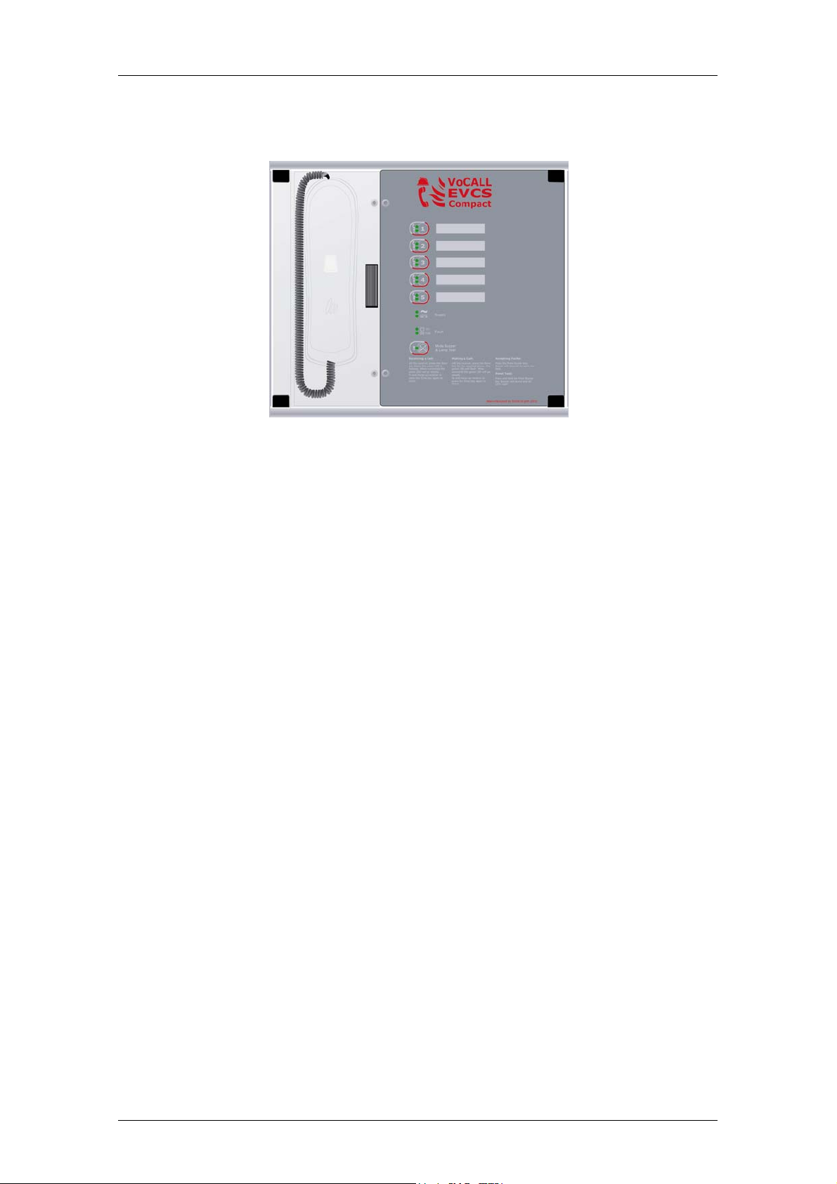
VoCALL Compact
5 Line Fire Telephone &
Disabled Refuge System
Site Name
Address
Contractor
Commissioned
User Manual & Log Book

VoCALL Compact User Guide & Log Book
Introduction
An EVCS is a fixed, secure, bi-directional, full duplex voice communication system to assist fire fighters
in an emergency in high rise buildings or large sites where Radio communication may not work, and
covers the operation of both fire telephones and disabled refuge systems.
The VoCALL Compact Emergency Voice Communications System (EVCS) is designed to fully comply
with BS5839-Part 9:2003 (abb. Pt9) for use as a Fire Telephone system, Disabled Refuge Call system
or as a combined system when both Fire Telephones and Disabled Refuge Points are required.
Suitability
Fire telephone systems are recommended for all public buildings and multi story buildings over four
floors by BS5588.
Disabled Refuge systems are required in buildings where the public or disabled staff gain access to any
floor other than the ground floor using lifts.
Product Overview
A VoCALL EVCS comprises of two functional blocks, the master handset and outstations, (type A, type
B or Jack points), with the quantities of these basic units being adjusted to suit the application.
The VoCALL Compact EVCS has been designed on a star topology; in the most cases this will reduce
the cable requirements from all ring-based systems. The topology consists of a spur formed from either
1 off two core core 1mm CSA cables (soft skin enhanced up to 500m per leg, MICC 200m per leg) to
each outstation.
Document DCC VCC7002-01 Rev 0 September 2008 Page 2 of 12

VoCALL Compact User Guide & Log Book
Operation
All conversations on the VoCALL Compact system are under the command of the control handset,
Pt9 envisages the majority of calls to be made by lifting the handset of an outstation (type A) or pressing
the call button (type B).
Receiving a Call:
Lift the receiver; press the Zone key where the green LED is flashing. When connected the green LED
will go steady and the outstation will be connected to the handset.
To end Hang-up receiver or press the Zone key again to place the outstation on HOLD (the zone led will
flash slowly when held).
Making a Call:
Lift the receiver; press the Zone key for the required outstation, the green LED on the zone key will
flash. When the outstation answers the call the green zone LED will go steady and the handset will
connect to the called outstation.
To end the call, Hang-up receiver or press the Zone key again to place the outstation on HOLD (the
zone led will flash slowly when held).
Conference Call:
Up-to five calls can be conference called, by answering the calls or dialling the calls as described above
the master handset must be involved in the call and only one conference group is allowed.
Accepting Faults:
Note the fault in the log book, then Press the Mute Buzzer key this will silence the “waterfall” tone, while
the fault exists the fault buzzer will “beep” once every 15 seconds until the fault is rectified. The buzzer
will resound on each new fault.
Panel Test:
Press and hold the Mute Buzzer key for 5 seconds, the fault Buzzer will sound and all status LEDs will
Light.
Document DCC VCC7002-01 Rev 0 September 2008 Page 3 of 12
Indications and Controls
Health Indicators (Green)
Healthy The system is ready for use and fault free.
AC Indicates healthy AC mains available.
DC Indicates the battery supply is available.
Fault Indicators (Yellow)
Zone Fault (! Led on each zone Key) steady indicated short circuit, flashing indicated
open circuit.
General Fault ( on the mute buzzer Key) A fault exists on the system.
CPU Fault The processor, main phone or watchdog timer have tripped, engineer
assistance is required.
Supply Fault Either the AC supply or DC supply is unavailable, or a fuse has ruptured.
VoCALL Compact User Guide & Log Book
Maintenance.
It is a requirement of BS5839pt9 that a maintenance agreement be in place for the EVCS, the
maintenance schedule should be as follows.
Weekly: Lift a different handset on the system each week and make a call to the control,
repeat each week until all points are tested, record results in the site log.
Monthly: Test one handset on each exchange by lifting the handset, followed by the master
calling the line, record results in the site log.
Quarterly: Engineer Call to check system operation.
Yearly: Engineer Call to check system operation and check Battery Health.
5 Yearly: Engineer Call to check system operation and replace the batteries.
Document DCC VCC7002-01 Rev 0 September 2008 Page 4 of 12

VoCALL Compact User Guide & Log Book
Important Safety Information
This Equipment must only be installed and maintained by suitably skilled and competent
person.
This Equipment is defined as Class 1 in EN60950 (Low Voltage Directive) and must be
EARTHED.
AUTION
C
ARNING
W
ARNING
W
ARNING
W
ARNING
W
Each exchange unit requires a 3A spur, returning to a breaker clearly marked Fire Telephone
DO NOT TURN OFF. If the units are distributed around a site it is essential all units are on the
same mains phase, as they are classified TEN 230V, powering from different phases can
mean a 440V potential can be present in a unit during a major fault incident.
Anti-static handling guidelines
INDOOR USE ONLY
SHOCK HAZARD-
ISOLATE BEFORE OPENING
TO REDUCE THE RISK OF FIRE OR
ELECTRIC SHOCK, DO NOT EXPOSE THIS
UNIT TO RAIN OR MOISTURE
THIS UNIT MUST BE EARTHED
NO USER SERVICABLE PARTS
Make sure that electro-static handling precautions are taken immediately before handling
PCBs and other static sensitive components
Before handling any static-sensitive items, operators should get rid of any electrostatic charge
by touching a sound safety earth, such as a radiator. Always handle PCBs by their sides and
avoid touching any components. PCBs should be stored in a clean, dry place that is free from
vibration, dust and excessive heat.
Storing the PCBs in a suitable cardboard box will also guard them against mechanical
damage.
Document DCC VCC7002-01 Rev 0 September 2008 Page 5 of 12

VoCALL Compact User Guide & Log Book
Batteries
The VoCALL Compact requires a single 12V 3.2AH sealed lead acid battery to provide backup power in
the event of mains failure as defined in BS5839pt9 for 24 hours standby and 30 minutes operation.
For 72hour standby and 1 hour operation a single 12V 7AH battery is required, the monitored charger in
the VoCALL Compact is capable of charging and monitoring these batteries.
Safety Information:
Sealed Lead acid batteries contain sulphuric acid which can cause burns if
exposed to the skin, the low internal resistance of these batteries means large
currents will flow if they are accidentally short circuited, causing burns and a risk
of fire- exercise caution when handling batteries.
Power Up Procedure:
Always apply mains power before connecting batteries, do not commission
VoCALL Compact on batteries, as the high inrush current required by the power
supply may rupture the battery fuse.
Always connect the Positive (Red +) terminal first.
Power Down Procedure
Disconnect the batteries before removing the mains power; always remove the
negative (Black – terminal) first
The VoCALL Compact EVCS is designed and manufactured in the UK by
Current Thinking Ltd,
Unit 91 Silver Briar
Enterprise Park East,
www.current-thinking.com
info@current-thinking.com
.
Sunderland,
SR5 2TQ.
Document DCC VCC7002-01 Rev 0 September 2008 Page 6 of 12

VoCALL Compact User Guide & Log Book
Certificate of Commissioning for an Emergency Voice
Communication System (EVCS) to BS5839 pt 9 (2002)
Site Name
Address
Customer
Address
Areas
Covered
System Design:
In accordance with section 1 of BS 5839 : Part 9 : 2002 sub clause 6 the system design is has in
accordance with the recommendations of this code except for the following:
Installation:
In accordance with section 3 of BS 5839 : Part 9 : 2002, the wiring has been inspected and tested
and been found to be in accordance with the recommendations of this code except for the
following:
Commissioning:
In accordance with Section 4 of BS 5839 : Part 9 : 2002: sub clause 21.2C
1. Intelligible conversation is heard at all locations.
2. All controls and indicators operate correctly
The system is accepted in good working order and, in accordance with BS5839: Part 9, 2002,
record drawings, operating instructions and a system log book have been supplied and received.
Attention has been drawn to the recommendations concerning user's responsibilities, particularly
those concerned with routine attention and test procedures in section 5, and an appointed
responsible person should be nominated by the customer in accordance with the recommendations
of Section 6 of BS5839 : Part 9 : 2002.
Engineer
Date
Position
Signature:
Document DCC VCC7002-01 Rev 0 September 2008 Page 7 of 12

Site Specific Information:
Equipment Locations
VoCALL Compact User Guide & Log Book
Master Handset
Phone Locations
Cable ID Line Area Served
1
2
3
4
5
Document DCC VCC7002-01 Rev 0 September 2008 Page 8 of 12

VoCALL Compact User Guide & Log Book
Log Book Page 1
Date Event or Work Done Engineer Company Signature
VoCALL System commissioned
Document DCC VCC7002-01 Rev 0 September 2008 Page 9 of 12

VoCALL Compact User Guide & Log Book
Log Book Page __
Date Event or Work Done Engineer Company Signature
Copy this page as many times as required
Document DCC VCC7002-01 Rev 0 September 2008 Page 10 of 12

VoCALL Compact User Guide & Log Book
Log Book Page __
Date Event or Work Done Engineer Company Signature
Copy this page as many times as required
Document DCC VCC7002-01 Rev 0 September 2008 Page 11 of 12

Notes:
VoCALL Compact User Guide & Log Book
The VoCALL Compact EVCS is designed and manufactured in the UK by
Current Thinking Ltd, Unit 91 Silver Briar, Enterprise Park East,
Sunderland, SR5 2TQ, United Kingdom.
Tel: +44 (0) 191 516 6533; Fax +44 (0) 191 516 6588; Email info@current-thinking.com
www.current-thinking.com
Document DCC VCC7002-01 Rev 0 September 2008 Page 12 of 12
 Loading...