

VNS Therapy SENTIVA M3000 Programmer, SENTIVA M2000 Wand, SENTIVA VNS Therapy System Technical Manual
Technical Guide
1

Table of Contents
PRODUCT OVERVIEW
VNS Therapy System Components and Support Materials
4
SENTIVA SYSTEM MANAGEMENT
Getting Started
In Oce Programming
Manual Programming
Tachycardia Detection/ Prone Position/Low Heart Rate Detection
Guided Programming
Scheduled Programming
Day/Night Programming
Therapy Protocols
Viewing Device Data
Session Reports
Export Full Programmer Copy
Trend Data
Timestamp Data
Functions of the Magnet
End of Service
Device Diagnostics
In the Operating Room
Preoperative System Checks
Programming & Diagnostics
GENERAL DOSING GUIDELINES
SenTiva Dosing Guidelines
MRI
SenTiva MRI Guidelines
9
22
23
24
30
33
35
37
39
39
40
41
42
45
45
46
50
50
51
57
60
TROUBLESHOOTING
Screen Freeze
Wand Connection or Communication Issues
Patient Cannot Feel Stimulation
Patient Cannot Feel Magnet Stimulation
Patient Does Not Perceive AutoStim Activation
High/Low Lead Impedance and Low Output Current Issues
Generator Battery Issues
Heartbeat Detection Issues
Tachycardia Detection Issues
66
67
71
72
73
74
77
79
80
2

INDICATIONS FOR USE
The VNS Therapy Programming System supports the delivery of personalized
Vagus Nerve Stimulation (VNS) Therapy for drug-resistant epilepsy (DRE).
This guide contains information on the use of the VNS Therapy® Programming
System with the Model 3000 Programmer and Model 2000 Programming
Wand. Please refer to the VNS Therapy® Programming System Physician’s
Manual for additional important prescribing and safety information.
Indication for Use
The VNS Therapy System is indicated for use as an adjunctive therapy in
reducing the frequency of seizures in patients 4 years of age and older with
partial onset seizures that are refractory to antiepileptic medications.
This overview is not intended to be a substitute for the VNS Therapy
Physician’s Manual.
Please note that not all products shown in this Technical Guide are cleared for
sale in all markets. Please check with your local representative to see what is
available in your area.
CONTACT INFORMATION
Contact Us
General inqiuries (for questions about LivaNova, LivaNova products, warranties,
etc. or to request a call from company representative) http://www.livanova.
com/contact-us/
24-hour Technical Support (for technical questions with programmer,
generator, or wand)
• 1 (866) 882-8804 (US and Canada)
• 1 (281) 228-7330 (Worldwide)
• 32 2 790 27 73 (Europe/EMMEA)
Mailing Address
LivaNova USA, Inc (formerly Cyberonics, Inc.)
100 Cyberonics Boulevard
Houston, TX 77058 USA
LivaNova Belgium NV
Ikaroslaan 83 B-1931
Zavantem, BELGIUM
©2019 LivaNova USA, Inc, a wholly-owned subsidiary of LivaNova PLC.
All rights reserved. LivaNova®, SenTiva®, AspireSR®, and VNS Therapy®
are registered trademarks of LivaNova USA, Inc.
3
Product Overview
INTRODUCTION TO VNS THERAPY
The VNS Therapy® System supports the delivery of personalized Vagus Nerve
Stimulation (VNS) Therapy for drug-resistant epilepsy (DRE).
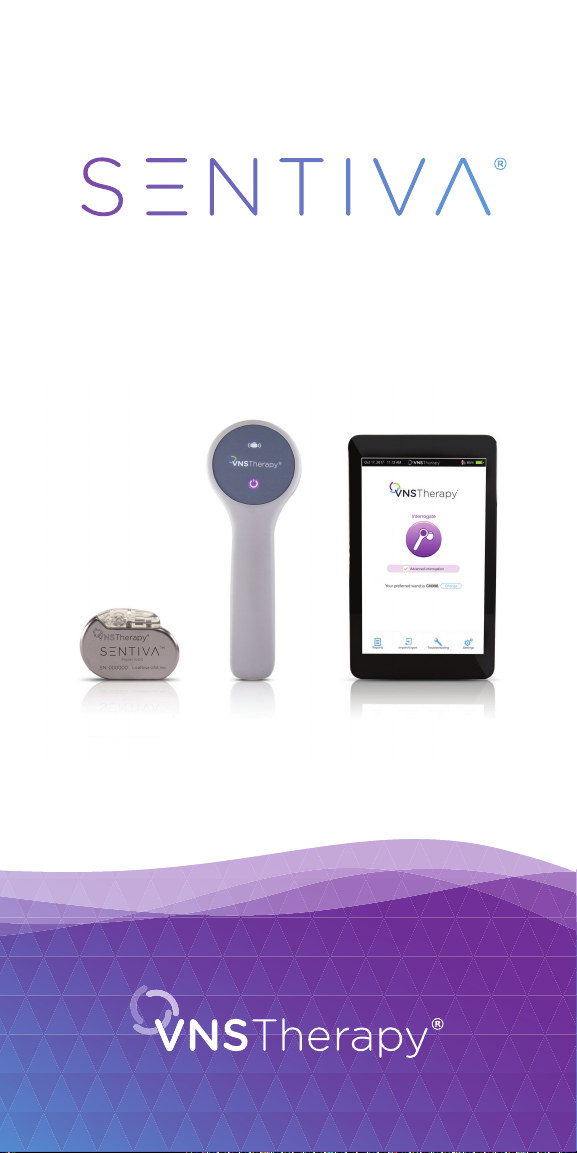
The VNS Therapy® System includes four parts:
• Generator and lead
• Programmer (tablet and software)
• Wand
• Magnet
Vagus Nerve
VNS Therapy
Generator
VNS Therapy
Lead
Pager Style
Magnet
Watch Style
Magnet
Programmer
Programming
Wand
4
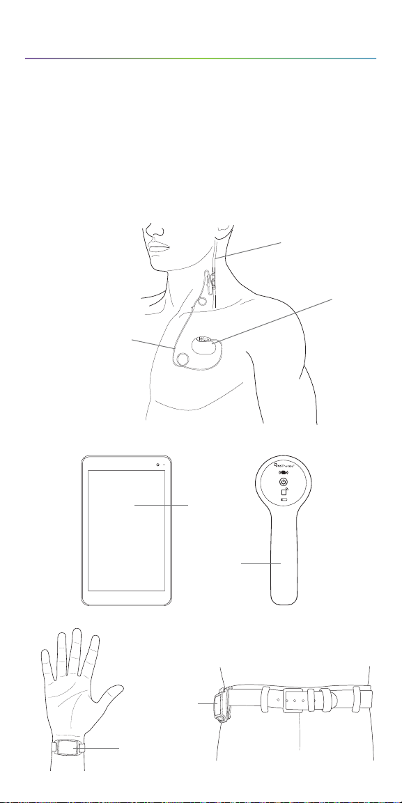
Generator and Lead
The implanted portion of
the VNS Therapy® System
consists of the generator and
a lead. The generator delivers
electrical signals, or pulses, to
the vagus nerve via the lead.
VNS Therapy
Lead
Vagus Nerve
VNS Therapy
Generator
Programmer (M3000)
The external portion of the VNS Therapy® System consists of a programmer
(a computer tablet with VNS Therapy® programmer software pre-installed)
and a wand (M2000). The programmer and the wand connect wirelessly.
This training module is developed for the M3000 programmer and M2000
wand. The programmer and wand are required for use.
The programmer and wand work together to:
• Interrogate (communicate with the generator) in order to adjust therapy
parameters for the generator
• Assess whether the generator and lead are functioning as expected
• View device histories
• Export session reports
Programmer
Programming
Wand
5
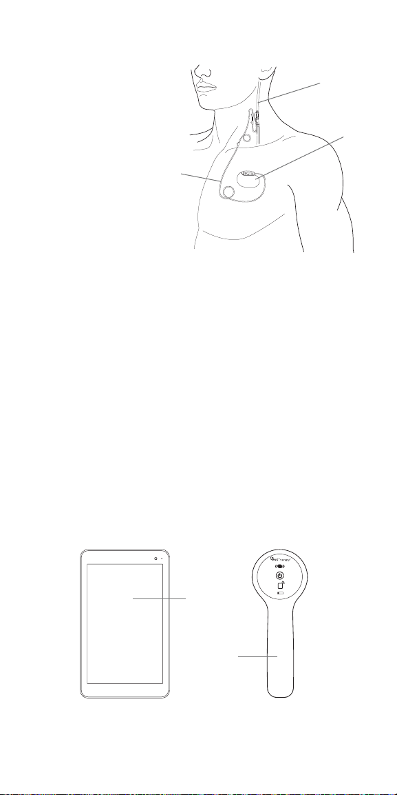
Wand (M2000)
The wand is designed to communicate wirelessly with the programmer
(M3000) at distances up to 3 meters (10 feet) under most conditions.
If communication is unstable, use the supplied USB cable to connect the
wand and the programmer instead.
Hold the wand no more than 1 inch away from the generator in order to
maintain good communication.
The wand operates on two AA lithium or alkaline batteries.
Programmer
Programming
Wand
Programmer
Charger
Wand
USB Cable
Magnet
The VNS Therapy® System has a patient controlled feature that can be activated
with a specially designed magnet.
The magnet can be used to:
• Attempt to reduce the intensity of or abort an oncoming seizure or
seizure in progress
• Temporarily inhibit stimulation
• Verify the generator is providing stimulation
• Reset the generator (in combination with the programmer and wand)
The magnet is available in two styles.
Pager Style
Magnet
Watch Style
Magnet
6

Product Compatibility
There are di erent VNS Therapy® generator models, including the new
SenTiva® generator.
The VNS Therapy® Programmer, Model 3000, and Wand, Model 2000, allow
you to interrogate and program the following VNS Therapy® generators:
• Model 102 Pulse™
• Model 102R Pulse Duo™
• Model 103 Demipulse®
• Model 104 Demipulse Duo®
• Model 105 ApsireHC®
• Model 106 AspireSR®
• Model 1000 SenTiva®
Please see the following chart to determine the generator’s compatibility
with other VNS Therapy® components.
The table below details the compatibility for all components
of the VNS Therapy®system
Programming
Lead
Tunneler
Wand
(Programmer)
Accessory
Pack
Patient
Essentials Kit
300* 302† 303† 304† 402 502 220201
TM
102† Pulse
102R† Pulse
Duo
103† Demipulse
104† Demipulse
Duo
105† AspireHC
106† AspireSR
1000† SenTiva
* No longer distributed
† Not for sale in all markets
TM
®
®
®
®
®
2000
(M250)
(M3000)
7

VNS Therapy® Modes
The VNS Therapy® System can function in three dierent modes:
NORMAL MODE
In Normal Mode, the generator initiates intervals of stimulation at preset ON
and OFF times throughout the day. Specific stimulation parameters are set by
the healthcare provider.
MAGNET MODE
Magnet Mode is an on-demand stimulation that attempts to abort or
de-intensify an oncoming seizure or a seizure in progress. The patient or
caregiver initiates Magnet Mode by passing a VNS magnet over the
implanted generator.
AUTOSTIM MODE
Automatic stimulation, or AutoStim, is an optional feature in some generator
models. AutoStim delivers stimulation when the generator detects a rapid
relative heart rate increase (≥20%) that may be associated with a seizure.
This feature works in conjunction with Normal Mode and can be inhibited
using the VNS magnet.
8
SenTiva System Management
GETTING STARTED
To get started, collect all the components of the VNS Therapy® System:
a) Touch-screen programmer preloaded with VNS Therapy®
programmer software
b) Wireless wand (Model 2000) with two AA lithium or alkaline batteries
c) Programmer charger
d) Type A-C USB cable (used to connect to charger to charge the programmer)
e) Type C USB cable (option to connect programmer to wand)
f) Type A-C USB drive (used to import/export protocols and export
session reports)
Before Using the Programming System
in a Patient Session
1. Charge the programmer
2. Turn the programmer ON
3. Check the programmer battery: Check the battery status on the
BATTERY INDICATOR at the top right corner of the programmer screen
4. Check the wand batteries: Confirm that the wand batteries are not low
5. Change the date and time if necessary. Accurate patient and device history
stored in the programmer depend on correct date and time settings
6. Connect the wand to the programmer
7. Interrogate the generator (check communication between the programmer
and the generator)
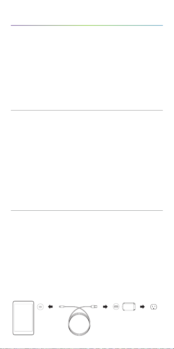
Charge the Programmer
Charge the programmer before use so that there is adequate battery power
during a patient session.
To charge the programmer:
1. Connect the adapter cord to the programmer and to the AC adapter
2. Plug the AC adapter into an outlet
A fully discharged battery may take four to five hours to charge.
Programmer Adapter Cord AC Adapter Outlet
9
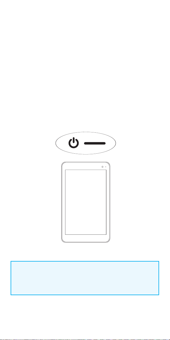
Turn the Programmer ON/OFF
Charge the programmer before use so that there is adequate battery power
during a patient session.
To turn programmer ON:
Press and hold the POWER button for 3 seconds and then release. You will then
see an on-screen logo, and the VNS software will start.
To turn programmer OFF:
Press and hold the POWER button for 3 seconds and then release. Follow the
on-screen instructions to shut down the programmer.
- After 10 minutes of inactivity, the screen will automatically turn o
- To manually turn the screen o: Quickly press and release the
POWER button. Use this method when you want to preserve battery,
but not shut down the Programmer
NOTE:
The POWER button may not respond if the programmer is still shutting
down. Wait for 30 seconds after a shutdown to restart the programmer.
10

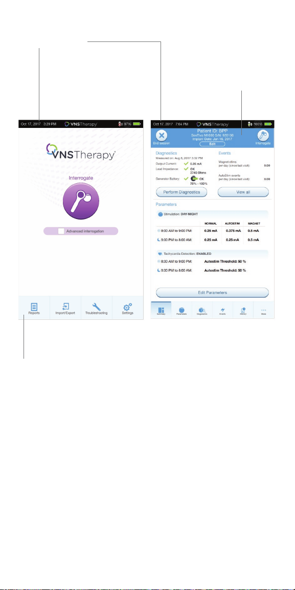
Navigation
There are two main screens on the programmer.
Each of these screens acts as a launching point for other functions.
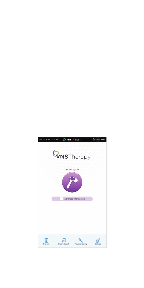
Main Screen – the first screen you see after turning on the programmer,
when the programmer is still OUT OF SESSION (programmer is not yet
communicating with a generator)
Summary Screen – the first screen you see once you are IN SESSION
(programmer is communicating with a generator)
OUT OF SESSION VS. IN SESSION
Available functions change based on whether the programmer is out of
session or in session.
• OUT OF SESSION (programmer is not communicating with a
generator)
• IN SESSION (programmer is communicating with a generator)
Quick Access Bar – From any software screen, tap the VNS Therapy® logo on
the title bar (black bar at the top of the screen) to access programmer settings
and system information.
This drop-down menu shows the following:
• Programmer date and time (OUT OF SESSION only)
• Wand connection status
• Programmer battery level
• Sliders to adjust the system volume and display brightness
• Programmer software version
• Wand software version and generator firmware (IN SESSION only)
Navigation Bar – From any software screen, tap the icons at the bottom of the
screen to access additional features
Patient ID Bar – If the blue patient ID Bar is showing on the screen,
the programmer is IN SESSION. To end the session, tap on the
END SESSION button at the left of the Patient ID Bar
11
Quick Access Bar
Patient ID Bar
Main Screen (Out of Session) Summary Screen (In Session)
Navigation Bar
12
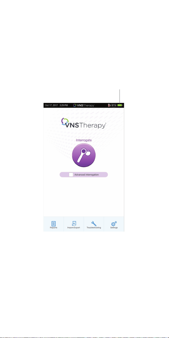
Check the Programmer Battery
Before using the programmer with a patient, confi rm that the battery is
fully charged.
To check the battery:
Look at the BATTERY INDICATOR in the top right corner of every screen
Battery Indicator
13
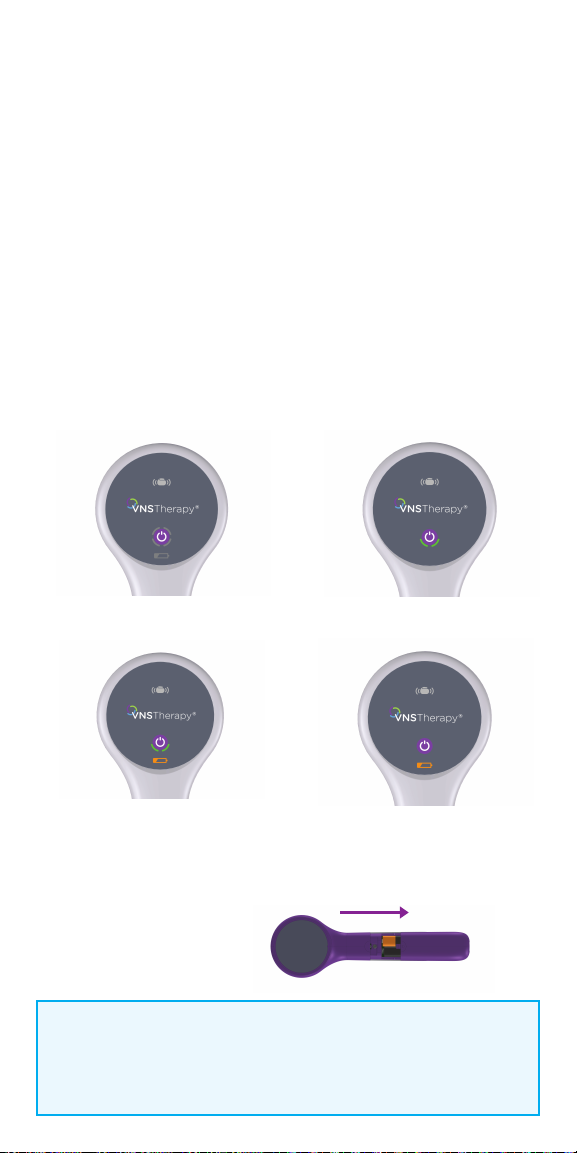
Check the Wand Batteries
1. To turn wand ON: Press and release the POWER button
• If the battery is OK, green arcs around the power button will light up to
indicate that the wand has power
- Two green arcs indicate that the wand is available for connection
with the programmer
- Four green arcs indicate that the wand is connected to the
programmer
• If the battery is low, the Low Battery Indicator will light up.
If this happens, replace the batteries before using the device
• If only the Low Battery Indicator lights up (no green arcs),
no communication will be possible until you replace the batteries
2. To replace batteries: If batteries are low, remove the battery compartment
cover on the back of the wand and replace the batteries with two new AA
lithium ion or alkaline batteries
Turn Wand Power On
Low Battery Indicator
Battery OK Indicator
Low Battery Power/
No Communication
Push and slide to open battery compartment
Wand Battery
Replacement
NOTE:
When illuminated, the flashing white icon at the top of the screen
indicates that there is communication with the generator.
14
Change Date and Time
Accurate patient and device history stored in the programmer depends on
correct date and time settings. Before using the programmer with a patient,
verify that the time and date on the programmer are correct. This will ensure
that the session is properly time-stamped.
1. Navigate to the Date & Time screen:
• OPTION 1: From the Main Screen, tap the VNS Therapy® logo on the title
bar (black bar at the top of the screen)
• OPTION 2: From the Main Screen, select SETTINGS from the bottom
navigation bar
• On the Settings Screen, tap the EDIT button at the top of the page
near the time
2. To change time: Tap the current display time and scroll up or down
3. To change date: Use LEFT or RIGHT ARROW to adjust the calendar,
and then tap the desired date
Title Bar
Navigation Bar
Main Screen
15
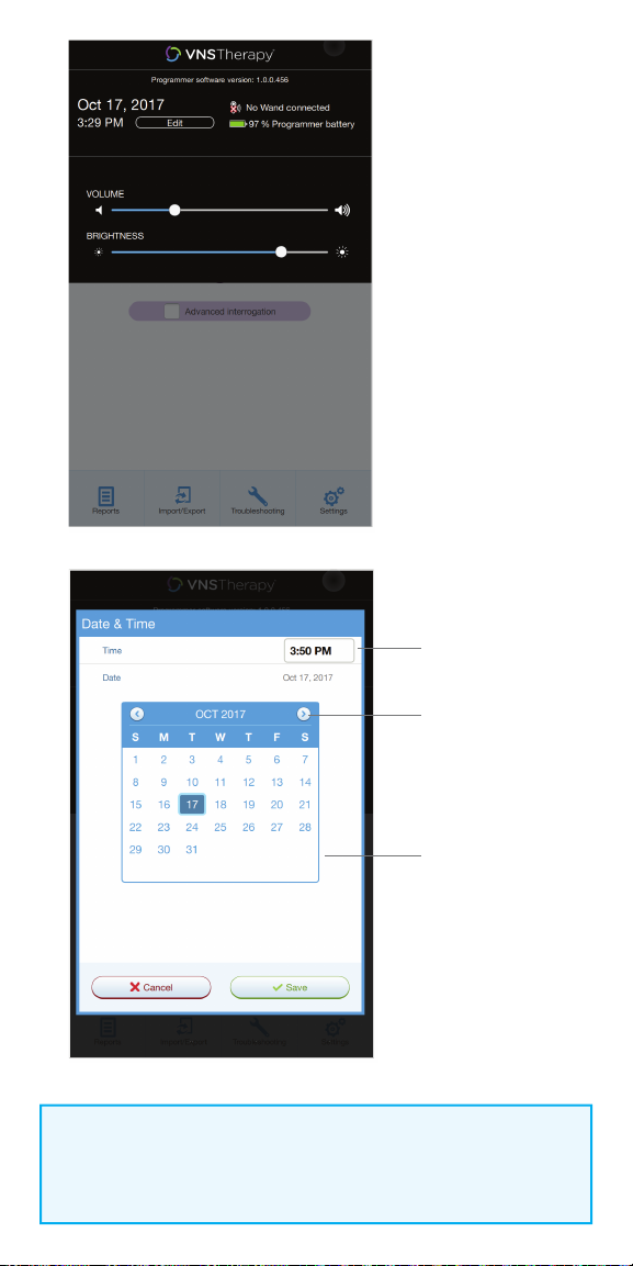
Tap and scroll to
change time
Use left and right
arrows to change
month
Tap the desired
date
NOTE:
You must adjust the programmer manually for time zones or Daylight
Savings Time.
16
Connect the Wand to the Programmer
The programmer and the wand can be connected wirelessly or with a backup
USB cable.
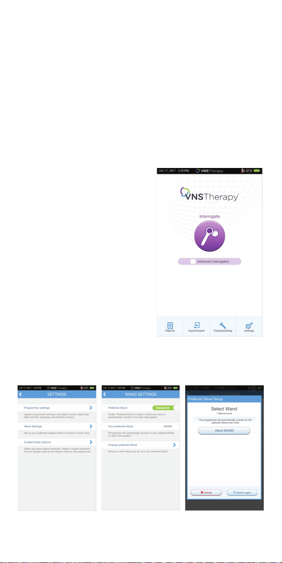
WIRELESS CONNECTION
To set up wireless connection:
1. Turn on the programmer
2. Turn on the wand. Look for two green lights on the wand, indicating that
power is on and the wand is ready to connect
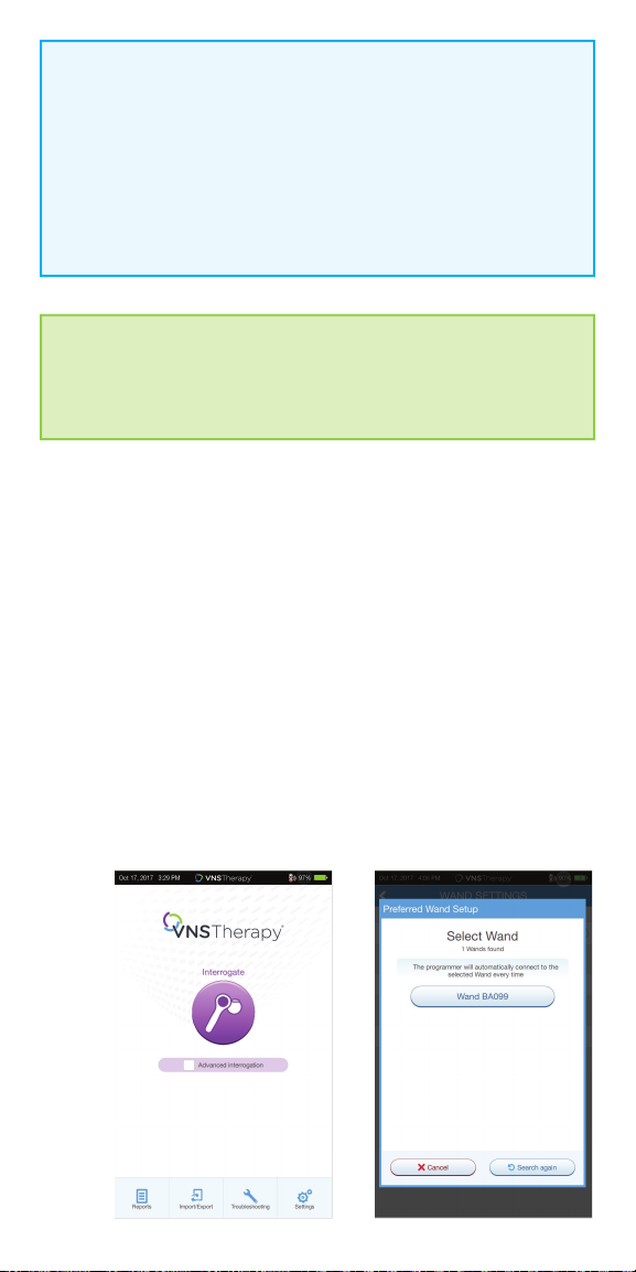
3. From the Main Screen on the programmer, tap on SETTINGS in the
Navigation Bar at the bottom of the screen
4. From the Settings Screen on the programmer, tap on WAND SETTINGS >
PREFERRED WAND
5. Tap on the preferred wand serial
number (found on the back of the
wand) to enable the preferred wand or
to change wands
6. Tap on BACK (upper left) to return to
the Main Screen
7. Look for two green arcs on the wand to
indicate the wand is available for
connection with the programmer. Once
availablity is established, four green arcs
on the wand to indicate that the
programmer and the wand are
connected. The green lights will stay on
for 10 minutes when the programmer
and wand are connected. When they are
not connected, the green lights will go
o after 2 minutes
Main Screen
17
NOTE: Wireless
“Preferred” connection - recommended for wands and programmers
that are always used together. Provides a quicker connection
when interrogating a patient’s generator because the programmer
automatically looks for the preferred wand. “Choose a wand” connection
recommended if there are several interchangeable programming systems
in your area. When interrogating a patient’s generator, the programmer
searches for all available wands in range.
SHORTCUT
You can set up a wireless connection automatically by starting the
interrogation. The programmer will prompt you to save the preferred
wand information as part of the workfl ow.
WIRED CONNECTION
Use the supplied USB cable to connect the wand to the programmer.
To set up wired connection:
1. Connect the programmer to the wand using the USB cable
2. Tap INTERROGATE on the programmer. The programmer will automatically
connect to the preferred wand and display the wand’s information on the
screen, indicating that the programmer and the wand are connected
3. Look for four green lights on the wand to indicate that the programmer and
the wand are connected. The green lights will stay on for 10 minutes when
the programmer and wand are connected. When they are not connected,
the green lights will go o after 2 minutes
18
Interrogate the Generator
You must interrogate the generator before performing other functions,
such as changing parameters or performing diagnostic tests.
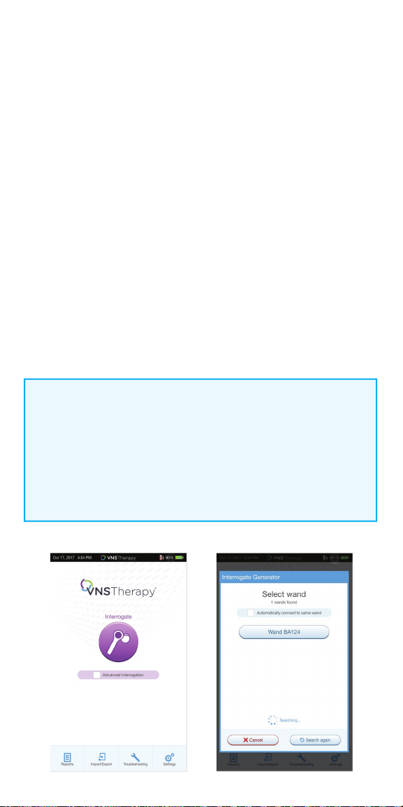
To interrogate the generator:
1. Turn on the programmer
2. Turn on the wand. Look for two green lights on the wand, indicating that
power is on and the wand is ready to connect
3. On the Main Screen, tap INTERROGATE
4. Preferred wand: If you have set up a preferred wand, the programmer
will automatically connect to the preferred wand and display the wand’s
information on the screen, indicating that the programmer and the wand
are connected
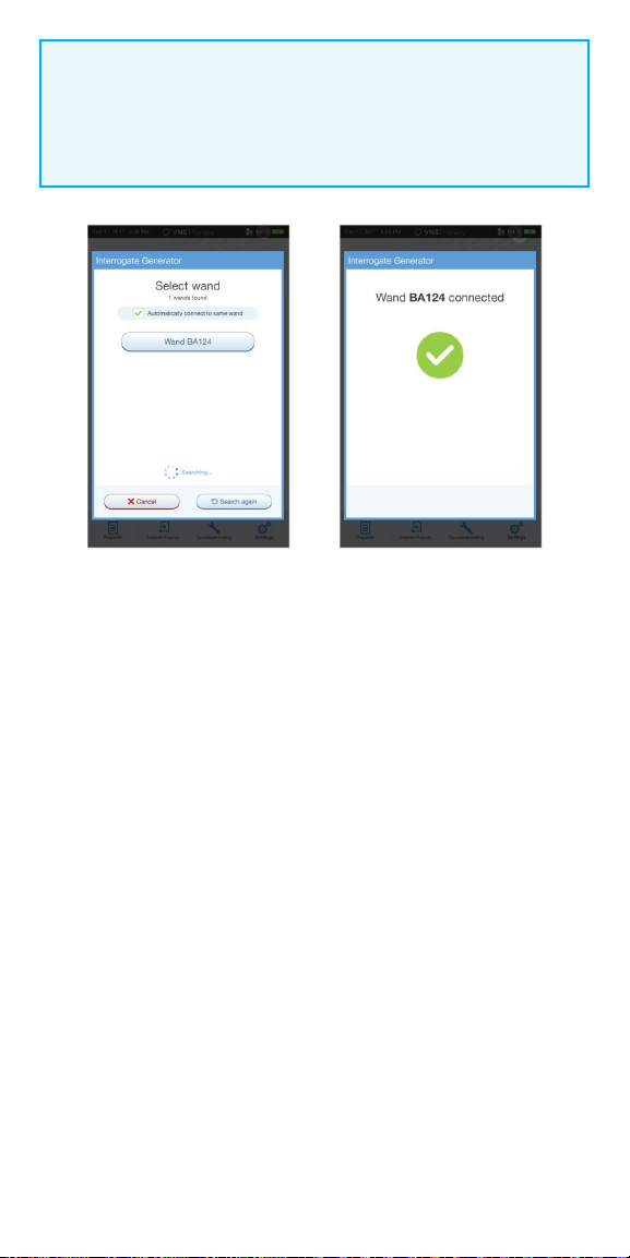
5. No preferred wand: If you have not set up a preferred wand, the
programmer will show all powered-on wands in range. Select the serial
number for the wand you intend to use. The programmer will connect to
that wand and display the wand’s information on the screen, indicating that
the programmer and wand are connected
6. Place the wand over the generator
7. If the interrogation is working, a generator icon will fl ash on the
wand screen
NOTE:
When the ADVANCED INTERROGATION box on the Main Screen is checked,
the programmer will download detailed data from the generator for the
previous 180 days during interrogation. These data will be displayed in the
Events and Trends tab which is accessible from the Navigation Bar.
For rapid interrogation, uncheck the ADVANCED INTERROGATION box.
19
NOTE:
Check box only appears if the programmer does not have a preferred
wand. If a preferred wand is selected, the programmer will search and
automatically connect to the preferred wand.
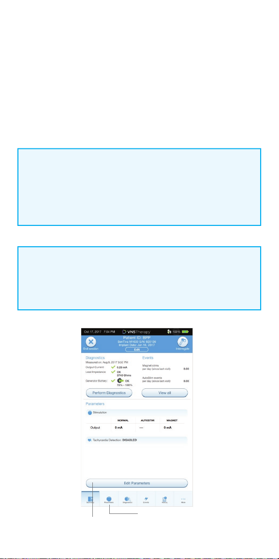
After a successful interrogation, the Summary Screen will display.
From this screen, you can perform the following functions:
•
View generator ID information, including model number and serial number
•
View and edit patient data, such as patient ID and implant date
•
View last known diagnostics data, such as lead impedance and battery status
•
Change settings to generator parameters, such as Normal, Magnet, AutoStim,
or Detection settings
•
Perform Diagnostics
•
View events and trends such as magnet activations and daily average
AutoStims
•
Access device history, including parameter settings associated with prior
o ce visits
•
Interrogate the generator again to verify parameters or refresh data
•
End programming session
•
Access other software options
20
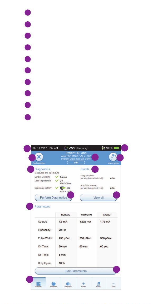
1
Current Programmer date and time
Wand connection and Programmer battery status
2
3
Ends current session
4
Generator and patient information
Interrogate generator
5
6
Last known diagnostics measurements
7
View stimulation events
8
Current parameters
9
Navigation bar to additional software features
Shortcut buttons
10
1
3
6 7
10 10
8
9
2
4
5
10
21

IN OFFICE PROGRAMMING
The SenTiva® (M1000) VNS Therapy System oers a number of new features
that help simplify and customize patient care.
The generator’s output current for the programmed stimulation in all modes
must be 0 mA for the first 14 days after implantation.
Manual Programming
Manually adjust parameters
Prone Position/Low Heart Rate Detection
Monitor the patient for episodes of low heart rate and prone body position
after an AutoStim or magnet activation
Guided Programming
Simplifies programming with option of Standard or Custom
Therapy Protocols
Scheduled Programming
Automatically change parameter steps according to a preset schedule
Day/Night Programming
Delivers two independent sets of therapy parameter schedules at dierent
times during a 24-hour period
NOTE:
The programmer must be IN SESSION to access these features.
NOTE:
At the end of each oce visit, the generator must be interrogated by
tapping the INTERROGATE button followed by tapping the END SESSION
button to ensure creation and accuracy of the session reports.
22
Manual Programming
Use Manual Programming to adjust stimulation and/or detection parameters
individually.
To manually program parameters:
1. From the Summary Screen, tap on the EDIT PARAMETERS button,
or tap on PARAMETERS in the Navigation Bar at the bottom of the screen
2. On the Parameters screen, select the Stimulation or Detection Tab.
Follow the on-screen prompts to make change to parameters
3. Tap APPLY CHANGES to program your changes
NOTE:
• After Implant: Set output current to 0 mA, slowly increase by 0.25 mA
increments until patient feels stimulation at a comfortable level
• Replacement Generators: Set output current at 0 mA, slowly increase
by 0.25 mA to previous therapy level to allow patient time to re-adjust
NOTE:
At the end of each o ce visit, the generator must be interrogated by
tapping the INTERROGATE button followed by tapping the END SESSION
button to ensure creation and accuracy of the session reports.
Edit
Parameters
Parameters
23
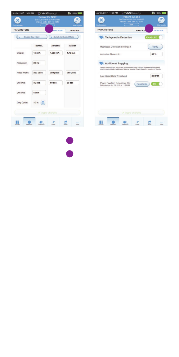
1
1
Stimulation Tab
2
Detection Tab
2
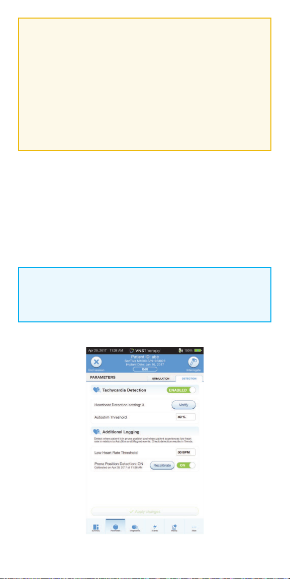
Tachycardia Detection
You may enable or disable Detection. If Detection is Disabled, then the model
1000 generators use only Normal and Magnet stimulation. If Detection is
Enabled, then parameters for AutoStim will become available, in addition to
Normal and Magnet parameters.
When you enable Detection for the first time, the software will prompt you to
set the Heartbeat Detection setting and AutoStim Threshold. These settings
work together to ensure the generator is accurately detecting the patient’s
heartbeats, and set the criterion for AutoStim delivery based on changes in
heart rate, respectively. Once Detection is enabled, you can adjust the settings
from the Detection tab as needed.
24
In order for the generator to accurately detect heartbeats, the heartbeat
detection must be set for the individual patient. Manually select from a range
of heartbeat detection sensitivity values: 1 (least sensitive; for use with largest
amplitude ECG signals) to 5 (most sensitive; for use with smallest amplitude
ECG signals). The setting will not change unless manually programmed to a
dierent value.
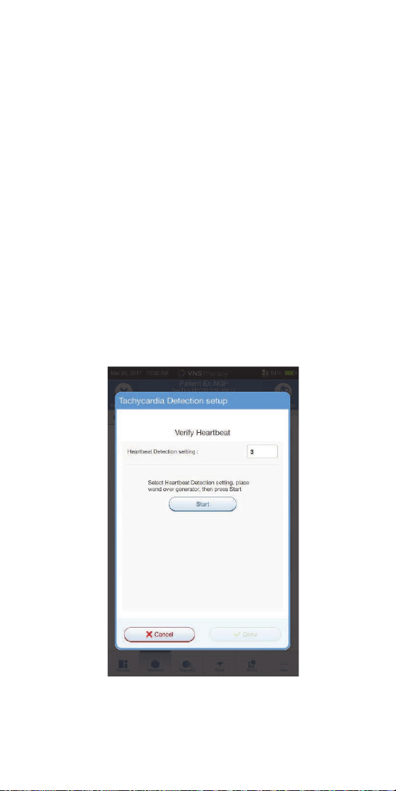
When Detection is enabled, the software will walk you through heartbeat
detection setting verification and AutoStim Threshold selection.
To Verify Heartbeat Detection:
1. Select VERIFY on the Detection Tab to confirm the accuracy of the heart
rate detected by the generator or to change the Heartbeat Detection setting
2. Place the Wand over the generator and press START to begin the test.
Keep the Wand over the generator during the entire Verify Heartbeat
Detection process. The generator will transmit a signal and the Programmer
will display the detected heart rate in beats per minute (BPM) for up to
two minutes
25
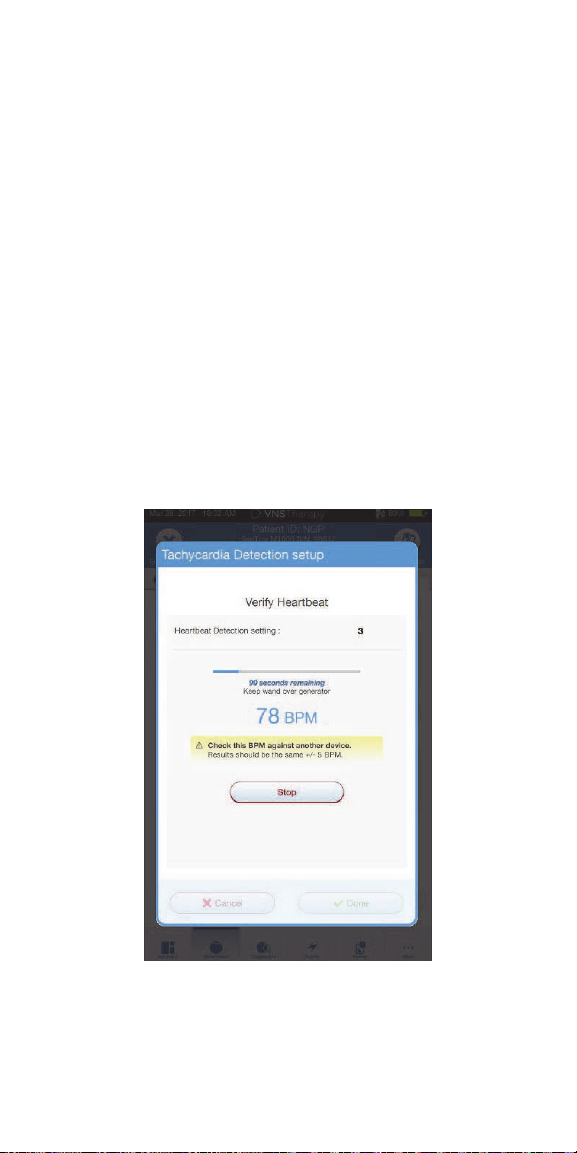
Wait for the heart rate display to stabilize (at least 10 seconds) and compare
3.
the generator-detected heart rate displayed on the Programmer with an
independent source (such as BPM from another ECG monitor or a manual
pulse count). Accurate detection should be within ±5 BPM or 10%. If the
heart rate reported by the Programmer is too high, then the Heartbeat
Detection setting should be adjusted downward (toward setting 1). If the
heart rate reported by the Programmer is too low or displays “?? BPM”,
then the Heartbeat Detection setting should be adjusted upward (toward
setting 5). Refer to “Troubleshooting” in the Physician’s Manual for more
information
If the heartbeat detection is verified before the two minute test completes,
4.
keep the Wand over the generator and select STOP on the screen. Once you
observe accurate heartbeat detection, you have completed the verification
process. If you are enabling Detection, select NEXT to set the AutoStim
Threshold. Otherwise, select DONE to return to the Parameter Screen
26
CAUTION:
For generators capable of heartbeat detection, if AutoStim or Magnet
stimulation is programmed on, the Verify Heartbeat Detection feature
may be interrupted if AutoStim or Magnet stimulation is activated
during the Verify Heartbeat Detection process. In this case, “?? BPM”
will display on the screen. If “?? BPM” displays, LivaNova recommends
you temporarily disable all output currents for generators capable of
heartbeat detection (i.e. program to 0 mA) and retry the heartbeat
verification. After the calibration process is completed, you may
reprogram the output currents as appropriate.
To set the AutoStim Threshold:
The AutoStim Threshold is a setting on the Detection Tab that can be set from
20% to 70% (in 10% increments). This setting allows you to determine the
minimum heart rate change required for AutoStim, and should be tailored to
the individual patient. For the most sensitive detection and the smallest heart
rate change for stimulation, choose 20%. For the least sensitive detection and
thus the largest heart rate change for stimulation, choose 70%.
NOTE:
Additional guidance for how to program this patient-specific setting
can be found in the VNS Therapy System Physician’s Manual.
27

Prone Position/Low Heart Rate Detection
To receive extra patient-specifi c information, you can confi gure the model
1000 generator to log low heart rate episodes and/or the occurrence of prone
position when these events occur within 7.5 minutes of an AutoStim or Magnet
Mode activation.
To enable Prone Position/Low Heart Rate Detection:
1. From the Summary Screen, tap on the EDIT PARAMETERS button, or tap on
PARAMETERS in the Navigation Bar at the bottom of the screen to go to
the Parameters Screen
2. On the Parameters Screen, tap on the DETECTION tab:
• Tap the LOW HEARTRATE THRESHOLD fi eld and select a threshold from
the pop up menu (range 30-60 BPM)
• APPLY CHANGES
• Turn on Prone Position Detection. The programmer will prompt you to
calibrate the generator orientation within the body
NOTE:
Tachyardia Detection must be enabled before this feature can be
enabled/programmed.
NOTE:
At the end of each o ce visit, the generator must be interrogated by
tapping the INTERROGATE button followed by tapping the END SESSION
button to ensure creation and accuracy of the session reports.
Low Heart
Rate
Threshold
Prone
Position
Toggle
28

To complete the Prone Position Detection setup:
1. Instruct the patient to sit or stand upright as straight as possible. Place the
wand over the generator and press NEXT on the programmer screen
2. Instruct the patient to lie down fl at on their back in the supine position.
Place the wand over the generator and press NEXT on the
programmer screen
3. Look for the on-screen confi rmation that Prone Position Detection is
now enabled
CAUTION:
Low heart rate and prone position events are for informational purposes
only. Detected events are not to be used for alarms or medical diagnosis.
29

Guided Programming
Use the Guided Programming feature to
adjust parameters to the next step of a
standard or custom protocol. This feature
simplifi es programming by allowing you
to increase or decrease parameters with
a single button. You can exit Guided
Programming at any time to adjust the
parameters manually.
In Guided Programming mode,
the SenTiva M1000 generator will:
• Keep the current mode,
protocol, and step in memory
• Increase or decrease
parameters to the next protocol
step in response to a single
button
NOTE:
Guided Programming mode is unavailable if Day/Night programming
is enabled.
To enable Guided Programming:
1. From the Summary Screen, tap on the EDIT PARAMETERS button, or tap on
PARAMETERS in the Navigation Bar at the bottom of the screen
2. On the Parameters Screen, tap on SWITCH TO GUIDED MODE button
at top of screen
3. On the Switch to Guided Mode Screen, select STANDARD PROTOCOL.
There is also an option of selecting a custom protocol
4. On the Parameters Screen - Guided Mode View, follow the on-screen
prompts to make selections. Tap APPLY CHANGES before leaving each screen
30

To review current therapy protocol steps:
In Guided Mode view, tap on the OVERVIEW button on the right
side of the screen
Overview
To change parameters in Guided Programming:
1. Select INCREASE STEP to increase parameters to the next protocol step.
Tap APPLY CHANGES to save
2. Select DECREASE STEP to change the parameters to the previous
protocol step. Tap APPLY CHANGES to save
3. To exit Guided Programming, press EXIT GUIDED
Decrease Step Increase Step
31

Standard Protocol Steps
Standard Protocol Persistent Parameter Settings
For information on creating Custom Protocols, see page 37
NOTE:
Guided Programming mode is unavailable if Day/Night programming is
enabled. In the Standard Therapy Protocol, maximum target for output
current for Normal Mode is 1.750mA. Increases above that target must be
done manually.
NOTE:
At the end of each o ce visit, the generator must be interrogated by
tapping the INTERROGATE button followed by tapping the END
SESSION button to ensure creation and accuracy of the session reports.
32

Scheduled Programming
The generator must already be in Guided Mode before Scheduled Programming
can be used. Use Scheduled Programming to automatically change parameter
steps according to a preset schedule. Scheduled programming may be useful to
patients who live far from their healthcare provider.
To enable Guided Programming:
1. From the Summary Screen, tap on the EDIT PARAMETERS button, or tap on
PARAMETERS in the Navigation Bar at the bottom of the screen
2. On the Parameters Screen, tap on SWITCH TO GUIDED MODE button at
top of screen
3. On the Switch to Guided Mode Screen, select either STANDARD or CUSTOM
protocol and tap NEXT
4. Tap APPLY CHANGES to enable Guided Mode
To turn on Scheduled Programming:
1. In Guided Mode View, tap the SCHEDULED-APPLY button
2. On the Scheduled-Apply Screen, tap on ENABLE NOW at the center
of the screen
3. On the next Scheduled-Apply screen, select the time interval between step
increases, then tap GENERATE SCHEDULE at the center of the screen.
Once a schedule has been generated you can follow the on-screen prompts
to make adjustments to the schedule
4. Tap APPLY CHANGES to program your changes
NOTE:
At the end of each o ce visit, the generator must be interrogated by
tapping the INTERROGATE button followed by tapping the END SESSION
button to ensure creation and accuracy of the session reports.
33

Scheduled Apply
NOTE:
If the patient resides in a di erent time zone or plans to travel, program
the schedule based on the patient’s local time zone to ensure therapy
changes occur at the intended times.
NOTE:
Protocols that utilize 0.25mA increases such as the Standard Protocol
require a minimum of 14 days between scheduled automatic titration
steps. Custom protocols that utilize 0.125mA increases require a 7-day
minimum interval between scheduled titration steps.
To exit Scheduled Programming, select EXIT GUIDED.
34

Day/Night Programming
Use Day/Night Programming to deliver two independent therapy parameter
schedules at di erent times during a 24-hour period. In Day/Night
Programming mode, the SenTiva M1000 will:
• Deliver therapy according to two independent sets of parameters
• Deliver each therapy protocol at a specifi ed time during a 24-hour period
To enable Day/Night Programming:
1. Confi rm that the programmer date and time are correct
2. Tap on the EDIT PARAMETERS button, or tap on PARAMETERS in the
Navigation Bar at the bottom of the screen
3. On the Parameters Screen, select ENABLE DAY/NIGHT.
When asked “Do you want to create a Day/Night program,” tap YES
4. On the Nighttime Tab, follow the on-screen prompts to make selections for
active start and end times
5. On the Daytime Tab, the remaining hours from the 24-hour cycle are
automatically shown as the daytime active period. Customize stimulation
parameters as desired
6. On the DETECTION TAB, set AutoStim thresholds for both day and night.
Tap APPLY CHANGES
7. On the Apply Changes Screen, review the changes made and then tap
CONFIRM
NOTE:
Day/Night Programming is only available in Manual mode and is
not available in Guided Programming mode. Guided Programming
mode is unavailable if Day/Night Programming is enabled. Day/Night
Programming can be disabled at any time.
NOTE:
Time zone changes and Daylight Savings time changes must be
programmed manually. The programmer does not automatically adjust
for time changes.
35

Day AutoStim
Threshold
Night AutoStim
Threshold
NOTE:
After programming, the patient will experience 15 minutes of the
alternate parameter set. Assess for tolerability during this time.
NOTE:
At the end of each o ce visit, the generator must be interrogated by
tapping the INTERROGATE button followed by tapping the END SESSION
button to ensure creation and accuracy of the session reports.
36

Therapy Protocols
You can access, create, and manage therapy protocols from the Main Screen
prior to interrogation. This allows you to defi ne the mode, output current,
and parameter settings before you begin working with a patient.
To access therapy protocols:
1. From the Main Screen, tap on the SETTINGS button in the
Navigation Bar at the bottom of the screen
2. Tap on the GUIDED MODE OPTIONS button
3. From the Guided Mode Options screen, tap on
THERAPY PROTOCOLS button
To create a custom protocol:
1. From the Therapy Protocols screen, select CREATE PROTOCOL
2. From the Create Protocol - Select a Starting Point screen, select
START FROM SCRATCH or choose an existing protocol as base
3. Add or delete steps (maximum of 7) and set the output currents for
each therapy mode. When you are fi nished, tap NEXT
4. Choose the custom persistent parameters that will be used in all
protocol steps. When you are fi nished, tap NEXT
5. Follow on-screen prompts to name the custom protocol.
When you are fi nished, tap SAVE
6. From the Therapy Protocols Screen, use the BACK arrow to
return to the Main Screen
37

Tap to delete steps
38

Viewing Device Data
Use the History tab to review historical information about the patient’s
experience with the device. You can:
• View Summary Data
• Review Magnet Activation Counts and Timestamps
• Review Inhibited Stimulation Timestamps
• Run Daily and Hourly Histograms
NOTE:
At the end of each o ce visit, the generator must be interrogated by
tapping the INTERROGATE Button followed by tapping the END SESSION
button to ensure creation and accuracy of the session reports.
View History Data
Summary data are stored in several diff erent locations:
1. To view current parameter settings:
After interrogation, parameter settings can be viewed on the
Summary Screen
Events
Current parameters
Events
History
2. To view a history of parameters that have been used with this
patient over time:
From the Summary Screen, tap on the HISTORY button to access these data
3. To create a session report:
Select VIEW SESSION REPORTS. Select the date and time of desired report
39

View and Export Session Reports
To view all session reports saved on the Programmer, select REPORTS on
the navigation bar from the Main Screen. Use the search fi eld and drop down
menus to fi lter the reports by Date and Time, generator model, or Patient ID.
Tap any session report to view.
This feature also allows you to export individual session reports to a USB drive.
To create an electronic copy (.pdf ):
1. Insert external media into the Programmer USB drive (type C)
2. View the session report of interest
3. Press EXPORT, and follow on-screen instructions
To transfer data between Programmers, select IMPORT/EXPORT on the
Navigation Bar from the Main Screen. This may be used to consolidate patient
data between multiple computers, or to copy a custom therapy protocol from
one Programmer to another.
To export a full Programmer copy do the following:
1. Insert external media into the Programmer USB drive (type C)
2. Select EXPORT DATA, and follow on-screen instructions
To import data to a new Programmer do the following:
1. Insert the external media containing the copied data into the “new”
Programmer USB drive
2. Select IMPORT DATA
3. Choose the database copy that will be merged with the existing
Programmer database
40

View Events & Trends Data
To view a summary of the therapy that
was delivered between o ce visits:
From the Summary Screen, tap on the
EVENTS button at the bottom of the screen
to access these data.
View Last Timestamps
Review Magnet Stimulation Counts
and Timestamps
To view Magnet Stimulation counts and timestamps:
1. From the Summary Screen, tap on the EVENTS button at the bottom
of the screen
2. Tap on the EVENTS tab
3. Tap on VIEW LAST TIMESTAMPS button. The button refl ects the total
number of timestamps recorded. The maximum number of timestamps
shown are the most recent 50 for the M1000 generator
41

Review Inhibited Stimulation Timestamps
From the same screen where you can view the Magnet Stimulation
timestamp information, you can also view the history of Magnet Inhibitions.
At the top are Magnet Stimulation timestamps and below are
Magnet Inhibition timestamps.
In each case, you can select the “date” header to select the time
intervals to view.
Stimulations
Inhibitions
NOTE:
Ensure ADVANCED INTERROGATION is selected on the Main Screen in
order to view Events and Trends after generator interrogation.
42

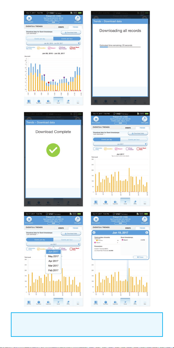
Review Daily or Hourly Histograms of
Trend Data
You can view histograms of trend data that may include:
• Tachycardia detections (without stimulation)
• AutoStim stimulations
• Magnet mode stimulations
• Prone position (model 1000 only)
• Low heart rate (model 1000 only)
NOTE:
The data download is only required for M1000 if the user wants to view
specifi c timestamps.
To view a histogram of trend data:
1. From the Summary Screen, tap on the EVENTS button in the Navigation Bar
at the bottom of the screen, and then select the TRENDS tab
2. To download timestamp information from the generator, place the wand
over the generator and tap the DOWNLOAD DATA button
3. Check the colored boxes to select the event types you want to include in
your histogram
4. Tap on the button displaying the date to adjust the timeframes
5. Tap on EVENTS PER DAY to show one month of detection data in a
day-by-day format
6. Tap on EVENTS PER HOUR to show detection data in an hour-by-hour
format. Choose the timeframe and event types you want to display
Events
43
NOTE:
To view more details, tap on the individual bars in the histogram.
44

FUNCTIONS OF THE MAGNET
On-demand Stimulation
• Programming is typically 0.25 mA more than Normal Mode output current.
• Apply or pass the magnet (with label-side of magnet facing chest) over
device for no more than 2 sec.
Inhibition
• Secure the magnet in place for > 65 secs with label-side of magnet facing
chest. When removed, stimulation will resume after one full o cycle
has elapsed.
Resetting
• The magnet is necessary to perform a reset with a programming wand if
necessary. See the VNS Therapy Physician’s Manual.
• It is recommended, except in cases of a medical emergency, that the
physician consult a LivaNova technical representative before a reset is
performed.
Daily Assessment of Generator Function
• Patients are instructed to swipe the magnet over the generator daily to
ensure that the device is working, particularly if they do not feel it or have no
voice change. The higher output current for the daily test enables the patient
to more readily detect the sensation caused by the stimulation.
Evaluating Magnet Mode Stimulation
• The Magnet Mode Diagnostics can be used to assess deliverability of the
magnet mode output current and the success of the initiation.
• The device retains detailed information on only the 50 most recent
activations but keeps count of all successful activations.
How to Replace the LivaNova Magnets
To order a new magnet, patients should contact their doctor. Doctors can
contact LivaNova at 1.866.332.1375 to order additional magnets for patients.
END OF SERVICE
Device longevity is dependent on stimulation parameters, impedance,
duration of implant, and battery voltage. Higher stimulation parameters as
well as higher duty cycles aect the longevity of the device, making the
projection shorter. Additional information can be found in the VNS Therapy
Physician’s Manual.
45

DEVICE DIAGNOSTICS
Several Diagnostics tests are available in the programming software to assess
functionality of the implanted system. You may access them after a completed
interrogation by selecting DIAGNOSTICS, or PERFORM DIAGNOSTICS on the
Summary Screen.
Depending on the model of generator interrogated, you may have access to
dierent types of tests. Typical tests include System Diagnostics, Normal Mode
Diagnostics, Magnet Diagnostics, and AutoStim Diagnostics. Make sure to
follow all the instructions on the Programmer screen, as they vary for
each selection.
It is important to note that the tests described in this section are designed for
assessing system functionality using the implanted components. Another test,
Generator Diagnostics, is designed specifically for use with a test resistor and
should only be accessed for troubleshooting scenarios during implantation
surgery. Please see “Troubleshooting” for more details on accessing Generator
Diagnostics.
The various test parameters and their values/meanings across the dierent
diagnostics tests are summarized in the following table.
46

Diagnostic/Parameter Result Summary
Lead Impedance
Description: Indicates measured or estimated impedance when delivering the
output current during testing and whether it’s within normal range.
Values/Results: Measured lead impedance value (ohms) and overall status of
OK, LOW, or HIGH
What Does the Value or Result Mean?:
OK: Impedance is within acceptable operating range.
No special attention is required.
LOW: Impedance is lower than expected and it may be indicative of a short
circuit condition or a defective generator.
See “Troubleshooting” for additional instructions.
HIGH: Impedance is higher than expected and the generator may not be able
to deliver the programmed therapy. See “Troubleshooting” for additional
instructions.
Generator Battery
Description: Indicates battery status of the generator using
one of the following:
• OK
• Intensified Follow-up Indicator (IFI)
• Near End of Service (N EOS)
• End of Service (EOS)
Values/Results: OK, IFI, N EOS, EOS
What Does the Value or Result Mean?:
OK: Battery level is within normal operating range and no special attention
is required.
IFI: The battery has depleted to a level where more frequent clinical
monitoring is recommended.
N EOS: The Generator should be replaced as soon as possible.
EOS: The generator is no longer supplying stimulation and immediate
replacement is recommended. If the generator is not replaced, it will
eventually lose the ability to communicate with the software.
Output Current/Current Delivered
Description: Indicates the stimulation output current delivered during the
Diagnostics test, and the test status based on the programmed settings
Values/Results: Output current value (mA) and overall status of OK or LOW
What Does the Value or Result Mean?:
Value indicates the stimulation output delivered during the diagnostic test.
OK: Current is being delivered at the programmed level.
LOW: Programmed current is possibly not being delivered at the specified level.
47

CAUTION:
Battery depletion can occur between oce visits. Therefore, LivaNova
recommends that epilepsy patients with magnet activation enabled
should perform a daily magnet activation to check stimulation.
If stimulation is not felt, instruct the patient to consult with the physician
to perform diagnostics testing.
All previously completed Diagnostics tests are listed in the history table on
the Diagnostics screen. Use the drop down menus to filter the reports by
type and/or date. Select any test to view details.
System Diagnostics
NOTE:
A System Diagnostics is performed for Model 1000 during the initial
interrogation, regardless of the type of interrogation (Advanced or
Rapid). The results are displayed on the Summary Screen and logged
as part of Diagnostics history. To perform a diagnostic test for a Model
1000 after the initial interrogation you can manually perform a System
Diagnostic test while in session.
The System Diagnostics test assesses the electrical continuity between
the generator and the bipolar lead when connected. The test measures
the generator’s ability to deliver programmed output current and the lead
impedance status. You can perform this test on all generators supported by
the Programming System during implantation and patient follow-up visits.
A successful System Diagnostics during surgery or post-implant shows that
both the generator and lead are working properly. LivaNova recommends you
perform a System Diagnostics test before other diagnostic tests.
Magnet Mode Diagnostics
The Magnet Mode Diagnostics test will let you know if the generator is able
to deliver the programmed magnet output current. To perform this test do
the following:
1. Select TEST MAGNET
2. Quickly pass the magnet over the generator (no more than 2 seconds)
3. Place the wand over the generator and use the on-screen button to
start the test.
If you do not successfully activate magnet stimulation, a message will
display on the screen indicating the magnet presence was not detected.
Pass the magnet over the generator again and restart the test.
48

AutoStim Diagnostics
The AutoStim Diagnostics test determines if the generator is able to deliver the
programmed AutoStim output current. The desired AutoStim output current
should be programmed before you perform the diagnostic test.
Generator Diagnostics
The Generator Diagnostics test is designed specifically for use with a test
resistor and should only be accessed for troubleshooting scenarios during
implantation surgery. Go to “Troubleshooting” for more details on using
Generator Diagnostics.
NOTE:
Once programmed ON, lead impedance measurement readings are
automatically performed once every 24 hours for Model 103 and
higher generators. Results from the 24-hour impedance check will be
reported on the Summary Screen upon initial interrogation.
49

IN THE OPERATING ROOM
The programmer and the programming wand can be connected wirelessly or
with a backup USB cable.
NOTE:
At the end of parameter adjustment in the Operating Room, the
generator must be interrogated by tapping the INTERROGATE button
followed by tapping the END SESSION button to ensure creation and
accuracy of the session reports.
Initial Implant Overview
1. Conduct ECG to select implant location
2. Perform preoperative system checks
3. Program Patient ID and implant date
4. Access and expose the vagus nerve
5. Create the generator pocket
6. Tunnel the lead
7. Place the electrodes
8. Add strain relief and tie downs
9. Connect the generator and lead
10. Perform System Diagnostic #1
11. Insert generator into pocket
12. Turn heartbeat detection ON
(for M106 and M1000 only)
13. Verify heartbeat detection
setting
14. Select AutoStim threshold
15. Secure generator to fascia
16. Perform System Diagnostic #2
and final interrogation
17. Close incisions
Perform Preoperative System Checks
BEFORE the surgery, prepare the VNS Therapy® System:
1. Charge the programmer
2. Turn the programmer ON
3. Check the programmer battery: Check the battery status on the
battery indicator at the top right corner of the programmer screen
4. Check the wand batteries: Confirm that the wand batteries are not low
5. Change the date and time if necessary. Accurate patient and device history
stored in the programmer depend on correct date and time settings
6. Connect the wand to the programmer
7. Interrogate the generator (check communication between the
programmer and the generator)
50

Program Patient ID and Implant Date
Enter or edit the patient data in the programmer during the preoperative
preparation, immediately before surgery. In the Operating Room you will be
prompted to enter the ID upon initial interrogation with the generator.
To enter or edit patient data:
1. Connect the wand to the programmer and interrogate the generator
2. On the Summary Screen, review the patient and generator information that
is displayed in the blue Patient ID bar at the top of the screen. Tap the EDIT
button below the patient information
3. On the Edit Patient ID screen, enter or change information as needed
4. Tap APPLY CHANGES and CONFIRM to enter the data
Edit
Button
Patient
ID Bar
51

Perform System Diagnostic #1
System Diagnostic #1 tests the continuity of the lead and confi rms delivery of
the programmed output current to the vagus nerve.
To perform System Diagnostic #1:
1. From the Summary Screen, tap on the PERFORM DIAGNOSTICS button,
OR tap on the DIAGNOSTICS button in the Navigation Bar
2. On the Diagnostics screen, tap TEST SYSTEM to start the test and confi rm
that the system is working correctly
3. Review the Diagnostics Test results and tap DONE
Turn Tachycardia Detection ON
Tachycardia Detection can be turned on from the Edit Parameters screen.
To turn Tachycardia Detection ON:
1. From the Summary Screen, tap on the EDIT PARAMETERS button,
OR tap on the PARAMETERS button in the Navigation Bar at the bottom
of the screen
2. On the Parameters Screen, select the Detection Tab and then tap on
ENABLE NOW to turn on Tachycardia Detection
52

Edit Parameters Detection TabEnable Now
Verify Tachycardia Detection Setting
To verify the Tachycardia Detection setting:
1. From the Summary Screen, tap on the EDIT PARAMETERS button,
OR tap on the PARAMETERS button in the Navigation Bar at the bottom of
the screen
2. On the Edit Parameters screen, select the Detection Tab and confi rm that
Tachycardia Detection is enabled. Verify the Heartbeat Detection Setting by
tapping the VERIFY button. If Detection has not been enabled, click on the
ENABLE NOW button to enable Detection
3. On the Tachycardia Detection Setup screen, select a Heartbeat Detection
Setting between 1 and 5. Small ECG signals need high amplifi cation
(e.g. setting 5), while large ECG signals do not (e.g., setting 1)
4. Keep the wand over the generator and press STAR T on the programmer
screen to begin the test. Wait at least 10 seconds for the reading to stabilize
5. Compare the heart rate measured by the system in beats per minute (BPM)
to the actual heart rate of the patient, and adjust the Heartbeat Detection
Setting until the system displays an accurate heart rate
6. Review changes, and then tap NEXT
NOTE:
Tachycardia Detection Setup (Step#3) is performed in the Operating
Room during initial setup. This will only be required to be performed in
the o ce if this step was not completed in the Operating Room or if an
adjustment is required post implantation.
53

54

Select AutoStim Threshold
The AutoStim Threshold is the percent heart rate increase over baseline that is
required to trigger automatic stimulation (AutoStim). Values range from 20%
(most sensitive) to 70% (least sensitive) and should refl ect the magnitude of
heart rate increase associated with the patient’s seizure.
To select the AutoStim Threshold:
1. From the Summary Screen, tap on the EDIT PARAMETERS button,
OR tap on the PARAMETERS button in the Navigation Bar at the bottom
of the screen
2. On the Parameters Screen, tap on the Detection Tab and confi rm that
Tachycardia Detection is enabled
3. Select an AutoStim Threshold. The threshold is the amount of heart rate
increase needed to trigger an AutoStim (in the range of 20% to
70% increase from baseline)
4. Tap APPLY CHANGES
55

Perform System Diagnostic #2 and
Final Interrogation
Before closing, perform Diagnostic Test #2 to confi rm that the system is
working properly and delivering the programmed output current.
To perform System Diagnostic #2 and Final Interrogation:
1. From the Summary Screen, tap on the PERFORM DIAGNOSTICS button,
OR tap on the DIAGNOSTICS button in the Navigation Bar at the bottom
of the page
2. On the Diagnostics screen, tap TEST SYSTEM to start the test
3. Review the results, tap DONE
4. Tap INTERROGATE button on the top right corner of the screen and then
tap the END SESSION button at the top left of the screen
Perform Diagnostics Button
Test System
Diagnostics Button
NOTE:
At the end of parameter adjustment in the
operating room, the generator must be
interrogated by tapping INTERROGATE
followed by tapping END SESSION to ensure
creation and accuracy of session reports.
56

General Dosing Guidelines
SENTIVA DOSING GUIDELINES
Phase 1: Output Current
Increase Output Current to therapeutic effect as tolerated by the patient
NORMAL MODE: 0.25 mA steps to therapeutic eect
1,2
AUTOSTIM MODE
AutoStim should be comfortable for patients
MAGNET MODE: Normal Mode + 0.25 mA
Magnet Mode should be > than AutoStim Mode
*
: Normal Mode + 0.125 mA
STANDARD PROTOCOL
1Visit 2 3 4 5 6 7
Output Current
Signal Frequency
Pulse Width
NORMALAUTOSTIMMAGNET
Signal ON Time
Signal OFF Time
Output Current
Pulse Width
ON Time
Output Current
Pulse Width
ON Time
mA
Hz
μsec
seconds
minutes
mA
μsec
seconds
mA
μsec
seconds
0.25
20
250
30
5
0.375
250
60
0.5
500
60
0.5
20
250
30
5
0.625
250
60
0.75
500
60
0.875
0.75
20
250
30
250
60
1.0
500
60
1.0
1.25
1.5
1.75
20
20
20
20
250
250
250
250
30
30
30
30
5
5
5
5
5
1.125
1.375
1.625
1.875
250
250
250
250
60
60
60
60
1.25
1.5
1.75
2.0
500
500
500
500
60
60
60
60
Suggested programming settings ≥ 2 weeks post-op
More frequent visits (1 - 2 weeks) are suggested in Phase 1
Multiple 0.25 mA increases may be made in a single visit to reach
therapeutic range sooner; ensure patient tolerability before making
additional adjustments
Dosing Notes
Continue to optimize dose to therapeutic effect or tolerability
Give patient time to adapt to parameter changes before making
additional adjustments
57
Phase 2: Duty Cycle
OFF TIME (minutes)
Not available with AutoStim Enabled
Increase duty cycle over time and assess clinical outcome
Adjustments to duty cycle should be less frequent (3 - 6 months)
0.2 0.3 0.5 0.8 1.1
7
58 44 30 20 15 10 6 4 2
14
69 56 41 29 23 15 9 6 3
21
76 64 49 36 29 19 12 8 4
81 71 57 44 35 25 16 10
30
ON TIME (seconds)
60
89 82 71 59 51 38 27 18 10
Recommended
Recommended progression for duty cycle
LivaNova recommends that stimulation with N ormal Mode ON time > OFF tim e be avoided.
Duty Cycle = (ON Ti me + 4 seconds) / (ON time + OFF Time), for which ON and O FF Time are
measured in seco nds.
Not recommended
1.8 3 5 10
5
Additional Settings for SenTiva
Tachycardia Detection
Heartbeat Detection*
Range (1 - 5)
ON/OFF
Start with Sensitivity 1 and verify heartbeat detection
update. Adjust setting if necessary until accurate
detection is reached.
Threshold for AutoStim*
(% heart rate increase)
Range (20 - 70%)
Prone Position*
Low Heart Rate*
Range (30-60 BPM)
*Tachycardia detecti on must be enabled
Set at or below the patient’s typical heart rate increase
during a seizure
If not available, start with 20% and adjust based on
clinical benefit or tolerability
Configure generator to log the occurrence of prone
position when they occur within 7.5 minutes of an
AutoStim or Magnet Mode activation
Configure generator to log low heart rate episodes
when they occur within 7.5 minutes of an AutoStim or
Magnet Mode activation
58

Strategies to Manage Side Eects
Evaluate tolerability after each adjustment
Side effects typically decrease over time
RECOMMENDED ORDER
1. Pulse Width If 500 250 µsec
2. Signal Frequency If 30 25 or 20 Hz
3. Output Current
FOR AUTOSTIM-RELATED SIDE EFFECTS*
1. Verify Heartbeat Detection
3,4
‡
§
0.125 mA
0.25 mA
Adjust Heartbeat Detection
sensitivity, if necessary
Pulse Width
2. AutoStim Parameters
Output Current (0.125 mA)
ON Time
3. Threshold for AutoStim 10%
Additional Information
Please see important safety information or visit www.VNSTherapy.com.
The VNS Therapy System is indicated for use as an adjunctive therapy in
reducing the frequency of seizures in patients 4 years of age and older with
partial onset seizures that are refractory to antiepileptic medications.
Incidence of adverse events following stimulation (>5%) were voice alteration,
increased coughing, pharyngitis, paresthesia, dyspnea, dyspepsia, and nausea.
This information is not intended to serve as a substitute for a complete and
thorough understanding of the material presented in the Physician’s Manuals
for the VNS Therapy system and its component parts and does not represent
full disclosure of all pertinent information concerning the use of this product,
potential safety complications, or ecacy outcomes.
REFERENCES: 1. Helmers SL, et al. Application of a computational model of vagus nerve stimulation. Acta Neurol Scand. 2012 Nov;126(5):336-43. 2. Heck C, Helmers SL, DeGiorgio CM. Vagus nerve
stimulation therapy, epilepsy, and device parameters: scientific basis and recommendations for use.
Neurology. 2002 Sep 24;59(6 Suppl 4):S31-7. 3. Morris GL Ill, Mueller WM. The Vagus Nerve Stimulation
Study Group E01-E05. Long-term treatment with vagus nerve stimulation in patients with refractory
epilepsy. Neurology. 1999;53(7):1731-1735. 4. Ben-Menachem E. Vagus nerve stimulation, side eects,
and long-term safety. J Clin Neurophysiol. 2001;18(5):415-418.
59

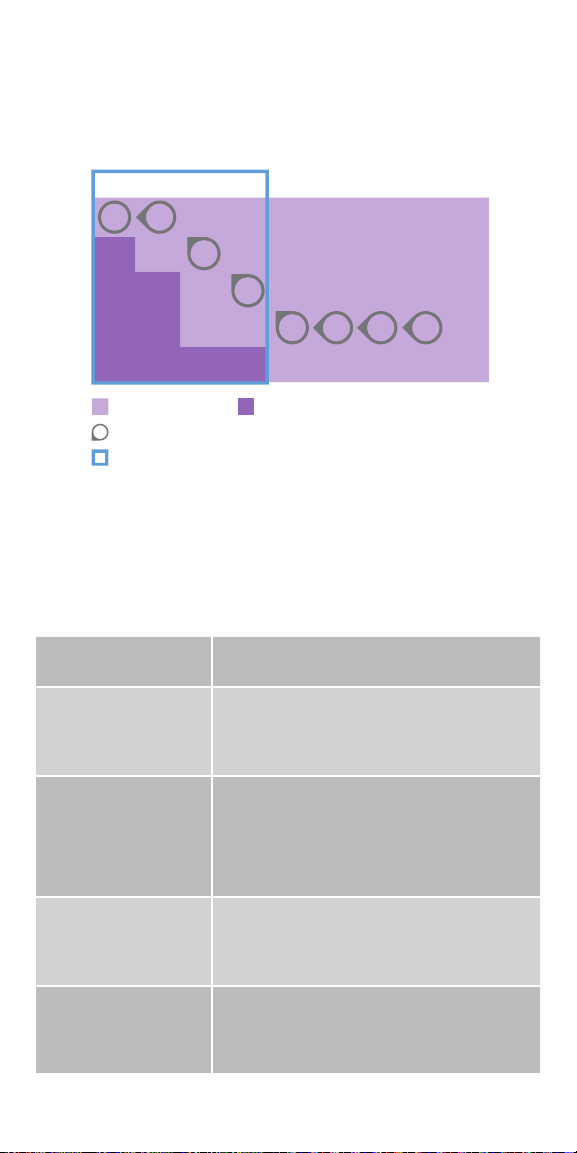
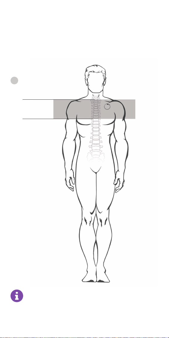
SenTiva MRI Guidelines
Scan Conditions - SenTiva® Model 1000
No special MRI equipment/coils required
GROUP A
Permissable Scan Area
MRI Exclusion Zone
C7
L3
Note: The scan iso-center must be
outside the exclusion zone
Generator in upper
left chest, at or above
armpit (above rib 4)†
† Patients with implants in other locations
must follow Group B scan conditions
Imaging techniques such as computed tomography, x-ray, and
ultrasound are safe to perform in the MRI exclusion zone.
Review the most current labeling prior to performing an MRI scan.
For full MRI safety information, refer to MRI Instructions for Use at
www.easy-mri.com
60

GROUP A
MR Conditional Yes
Static Magnet Strength 1.5T or 3T
Scanner Type Horizontal field, cylindrical closed-bore 1.5T or
3T scanner
Operating Mode Normal Operating Mode
Exclusion Zone Body coil: C7-L3
Transmit-receive head or extremity coil: C7-T8
Max Spatial Gradient ≤3000 Gauss/cm
Max Slew Rate 200 T/m/s
RF Coil Transmit: Body coil or Transmit-receive head or
extremity coils
Receive: No Restrictions
Max SAR Transmit head coil: 3.2 W/kg
Transmit body coil: 2.0 W/kg
System Programming Stimulation OFF Sensing OFF*
*for select models with AutoStim mode
Optional device features OFF (Model 1000 only)
Exposure Time Transmit head or extremity coil: No restrictions
Transmit body coil: ≤ 15 minutes of active scan
time within a 30 minute window
Additional Restrictions Transmit head or extremity coil: none
Transmit body coil: Circularized Polarized mode
only
For full MRI safety information, the VNS Therapy System Physician’s
Manual can be found at www.easy-mri.com
For technical product questions, contact LivaNova Technical Services
at 1-866-882-8804
61
Scan Conditions - SenTiva® Model 1000
implanted lower than rib 4
(below armpit level)
Requires local transmit-receive coil
Availability may vary
GROUP B
MRI Exclusion Zone
C7
T8
Permissable scans include
head, knee, ankle, and wrist
Imaging techniques such as computed tomography, x-ray,
and ultrasound are safe to perform in the MRI exclusion zone.
Review the most current labeling prior to performing an MRI scan.
For full MRI safety information, refer to MRI Instructions for Use at
www.easy-mri.com
62

GROUP B
MR Conditional Yes
Static Magnet Strength 1.5T or 3T
Scanner Type Horizontal field, cylindrical closed-bore 1.5T or 3T scanner
Operating Mode Normal Operating Mode
Exclusion Zone C7-T8
Max Spatial Gradient ≤3000 Gauss/cm
Max Slew Rate 200 T/m /s
RF Coil Transmit-receive head or extremity coils
Max SAR Transmit-receive head coil: 3.2 W/kg
System Programming Stimulation OFF Sensing OFF *
*for select models with AutoStim mode
Optional device features OFF (Model 1000 only)
Exposure Time Transmit head or ex tremity coil: No restrictions
Additional Restrictions None
For full MRI safety information, the VNS Therapy System Physician’s
Manual can be found at www.easy-mri.com
For technical product questions, contact LivaNova Technical Services
at 1-866-882-8804
63

Special Cases
Lead only
≤ 2 cm remaining*
Suspected Lead Break
OR
Lead only
>2 cm remaining
Lead only
≤ 2 cm remaining*
Exclusion Zone C7-T8 None
MR Conditional Yes Yes
Static Magnet
1.5T or 3T 1.5T or 3T
Strength
Operating Mode Normal Operating
Normal Operating Mode
Mode
Max Spatial Gradient ≤3000 Gauss/cm ≤3000 Gauss/cm
Max Slew Rate 200 T/m/s 200 T/m/s
RF Coil Transmit-Receive head
or extremity coil only
Transmit: Body or
transmit-receive head or
extremity coils
Receive: No Restrictions
Max SAR Transmit/receive head
coil: 3.2 W/kg
Transmit head coil:
3. 2 W/kg
Transmit body coil:
2.0 W/kg
64

To ensure eective communication with the MRI center, complete the
Patient MRI Form. Send with the patient to their MRI appointment.
Download from easy-mri.com
Pre-MRI Instructions
An appropriate healthcare professional with access to a VNS Therapy
programming system must prepare the VNS Therapy generator before the
patient enters an MR system room.
1. Interrogate the VNS Therapy generator* and record the generator settings
2. Perform System Diagnostics to ensure proper operation of the generator
3. Reprogram the Output Current parameter settings for Normal Mode,
Magnet Mode, and AutoStim Mode† as follows:
• Output Current (mA): 0.0
• Magnet Current (mA): 0.0
• AutoStim Current (mA): 0.0 and Tachycardia Detection “OFF”
4. Turn o any other optional device features (Model 1000 only)
5. Interrogate the generator* to verify that programming was successful
6. Verify that placement of the VNS Therapy system is located between the
C7 and T8 vertebrae
7. Instruct the patient to notify the MR system operator of pain, discomfort,
heating, or other unusual sensations so the operator can terminate the
procedure, if needed
Post-MRI Instructions
After the MRI procedure, an appropriate healthcare professional with access to
a VNS Therapy programming system should assess the condition of the VNS
Therapy system.
To assess the VNS Therapy system:
• Interrogate the VNS Therapy generator
• If the generator was reset during the scan, reprogram the serial
number, patient ID, and implant date, as needed
• Program the patient’s therapeutic parameters as they were before the MRI
procedure
• Perform System Diagnostics. Results should indicate Impedance=OK
• Interrogate the generator again to confirm that reprogramming was
successful
* When an interrogation is performed by the programming software, the generator serial number,
implant date, stimulation parameters, and generator operating time are automatically logged in
the programmer database. This information may be retrieved from the database at any time after
interrogation.
† for select models with AutoStim mode
For full MRI safety information, the VNS Therapy System Physician’s Manual
can be found at www.easy-mri.com. For technical product questions, contact
LivaNova Technical Services at 1-866-882-8804
65

Troubleshooting
This section provides steps to resolve error conditions with the
programming system components or with the implanted generator and
lead. For other programming system issues not addressed in this section,
please contact LivaNova.
Contact Us
General Inqiuries (for questions about LivaNova, LivaNova products,
warranties, etc. or to request a call from a company representative)
http://www.livanova.com/contact-us/
24-hour Technical Support (for technical questions with programmer,
generator, or wand)
• 1 (866) 882-8804 (US and Canada)
• 1 (281) 228-7330 (Worldwide)
• 32 2 790 27 73 (Europe/EMMEA)
Mailing Address
LivaNova USA, Inc (formerly Cyberonics, Inc.)
100 Cyberonics Boulevard
Houston, TX 77058 USA
LivaNova Belgium NV
Ikaroslaan 83 B-1931
Zavantem, BELGIUM
Screen Freeze
1. Press and hold POWER button on the
programmer for at least three seconds;
release and follow onscreen instructions
to shut down the tablet
2. If the computer does not shut down,
press and hold POWER button to force
a shutdown (may take 10+ seconds)
3. Restart the programmer
66

Wand Connection or Communication Issues
WAND NOT CONNECTING TO PROGRAMMER (WIRELESS)
Potential reasons for no wireless connection between the Wand and the
Programmer include the following:
• Wand not powered on
• Depleted Wand batteries
• Electromagnetic interference (EMI), such as OR lights
• Defective Wand or Programmer
Error Messages
“Wand (serial number of connected wand) not found”
Check Wand Power - Press and release power button
“No wands found…”
Yes
Replace batteries
No
Verify Wand Selection
• Confirm wand ID matches wand
selected on programmer
Check for Interference
• Confirm wand is 3-4 feet away
from all electronic equipment
Reconnect to Wand
Connect with backup cable
No
Successful
Connection?
Yes
No
Is the low battery
icon illuminated?
Retry connecting to wand
Successful
Connection?
Proceed with intended use
Connection?
No
Contact LivaNova Technical Support
No
Successful
Are the green
power indicator
Yes
Yes
Yes
lights on?
No
67

ANOMALOUS BEHAVIOR OR NON-RESPONSIVE SYSTEM
Non-responsive Programmer or Wand
Issue:
Solution Steps for Programmer:
Charge programmer – Plug programmer into A/C outlet
Shut down – Press and hold the power button for 5 seconds,
and then release. Follow on-screen instructions to shut down
If programmer is still non-responsive, press and hold power button to
force a shut down (approximately 10 seconds)
Reboot – Power on the programmer
Solution Steps for Wand:
Verify wand battery power - If the orange low battery light is on,
replace the wand batteries
Perform soft reset - Press and hold wand power button for 5
seconds and release
Device
Responsive?
Yes
Verify:
• Programmer has adequate charge
• Programmer has correct date/time
No
Contact LivaNova Technical Support
Yes
Proceed with intended use
68

WAND NOT CONNECTING TO PROGRAMMER (BACKUP CABLE)
Potential reasons for no connection between the Wand and the Programmer
via backup cable include the following:
• Improper cable connection between Wand and Programmer
• Depleted Wand batteries
• Improper USB port recognition of the Programmer cable
• Defective Wand or Programmer
Error Messages
“Wand not connected…”
Check Wand Power - Press and release power button
Does wand power
indicator light appear?
YesNo
Replace batteries
No
Verify Cable Connection
• Confirm cable is connected to wand and programmer.
Reinsert if necessary
Successful
Connection?
No
Contact LivaNova Technical Support
Retry connecting to wand
Successful
Connection?
Yes
Proceed with intended use
Yes
69

WAND NOT COMMUNICATING WITH GENERATOR
Potential causes for communication issues between the Wand and generator
include the following:
• Depleted Wand batteries
• Moving Wand away from generator during communication
• Electromagnetic interference (EMI), such as OR lights
• Generator battery at End of Service (EOS)
• Magnet placed over generator
• Defective Wand, Programmer, or generator
Error Messages
“Generator not found...”
“Error communicating with generator…”
Check Wand Placement
• Confirm wand is placed over the generator
• Rotate wand 45 degrees
• Confirm generator pocket is not more than 1 inch below the
skin, not muscle (during surgery)
Remove Magnet Presence
• Confirm magnet is not placed over the generator
Retry Communication
No Yes
Contact LivaNova Technical Support
Successful
Connection?
Proceed with session
70

Patient Cannot Feel Stimulation
• Possible causes:
- Patient has become accustomed to the programmed setting
- Generator battery at end of service (EOS)
- “High” lead impedance, defective, or disabled generator
- Short-circuit condition within the lead
• For more detailed information, consult the Troubleshooting section of the
VNS Therapy® System Physician’s Manual
Patient Report
“Cannot feel stimulation”
Interrogate the generator
“Disabled Message?”
YesNo
• Perform a System Diagnostics
• Record results
Lead Impedance Result
“Ok”
Output Current Result
“Ok” “Low”
The generator is able to deliver
programmed output current and the
VNS system is working properly
Probable Diagnosis: The patient has
grown accustomed to stimulation
but is still receiving the programmed
therapy
“High” or
“Low”
For possible causes, see
“Troubleshooting” in the
programming system
“The generator is currently disabled due to
[CAUSE]. The generator is NOT supplying
stimulation.”
Note: If the CAUSE is “a wand reset” and the
reset was intended, continue with the session
Physician’s Manual
The generator cannot deliver programmed
output. Consider lowering output current
while increasing pulse width
Contact Clinical Technical Support
Record the CAUSE
71

Patient Cannot Feel Magnet Stimulation
• Possible causes:
- Patient has become accustomed to the programmed setting
- Incorrect technique for swiping magnet
- Magnet output current is programmed to 0 mA
- Generator battery at end of service (EOS)
- Device implanted too deep in the chest
- Defective generator or disabled generator
- “High” lead impedance
- Short-circuit condition within the lead
Patient Report
“Cannot feel magnet activation”
Is Magnet Current ≥ the
Output Current? and
Magnet ON time
>7 seconds?
Yes
• Display Device History or Events
• Record number of magnet
activations
• Swipe the magnet
• Reinterrogate the device
• Display Device History or Events
• Perform a System Diagnostics
• Record results
Lead Impedance
“High” or “Low”
See
“Troubleshooting”
in the
programming
system Physician’s
Manual
Lead Impedance “Ok”.
Output Current “Ok”
Magnet Mode
stimulation is
functioning properly
and the patient
may have become
accustomed to the
settings. Consider
raising the magnet
current if perceived
stimulation is desired
No
Consider adjusting
Interrogate the
generator
Magnet settings
may be too low for
patient to perceive.
magnet setting
Did the magnet
activations increase?
No
Generator is delivering the magnet stimulation.
Consider raising the magnet current if perceived
stimulation is desired
Lead Impedance “Ok”.
Output Current “Low”
Generator cannot
deliver the
programmed magnet
output due to
increased impedance.
Consider lowering
magnet output current
while increasing
magnet pulse width
“Disabled Message?”
No
“The generator is currently
disabled due to [CAUSE].
The generator is NOT supplying
stimulation.”
Note: If the CAUSE is “a wand
reset” and the reset was
intended, continue with the
session
Record the CAUSE
Yes
Indication that the
generator did not
sense a magnet.
Swipe the magnet
again and repeat
Magnet Mode
Diagnostics. If the
message appears
again call Technical
Support
Yes
Contact LivaNova Technical Support
72

Patient Does Not Perceive AutoStim
Activation
• Possible causes:
- AutoStim Threshold is too high (e.g., 70% threshold versus 50%)
- Patient has become accustomed to the programmed setting
- AutoStim output current is programmed to 0 mA
- Generator battery at end of service (EOS)
- Defective generator or lead
- Disabled generator
Patient Report
“Cannot feel AutoStim”
Interrogate the generator
• Confirm Detection is enabled
• Confirm AutoStim output current is set to > 0 mA
and ≥ Normal output current
Confirm heartbeat detection (See “Troubleshooting” in
the programming system Physician’s Manual
Perform an AutoStim Diagnostics and record results
Current Delivered
• Examine oce visit data in Device History or Events
• Investigate consecutive oce visits to identify any
changes in the average number of AutoStims per day
delivered
If > 0 If 0
The generator is delivering
AutoStim. If perceived
stimulation is desired,
consider raising the
AutoStim current
Re-evaluate at next oce visit
If the average number of AutoStim activations per day
since last oce visit is 0 and the patient has had seizures
during this period, adjust the AutoStim Threshold setting
toward 20%
Repeat this process at subsequent oce visits until the
patient perceives stimulation or the device confirms the
logging of events
Note: Decreasing the detection threshold increases
the likelihood of detecting heart rate rises associated
with seizures, but may increase the overall number of
AutoStims delivered and impact battery longevity
“Disabled Message?”
No
“The generator is currently disabled
due to [CAUSE]. The generator is
NOT supplying stimulation.”
Note: If the CAUSE is “a wand
reset” and the reset was intended,
continue with the session
Current Not
Delivered
Contact Clinical Technical Support
Yes
Record the CAUSE
73
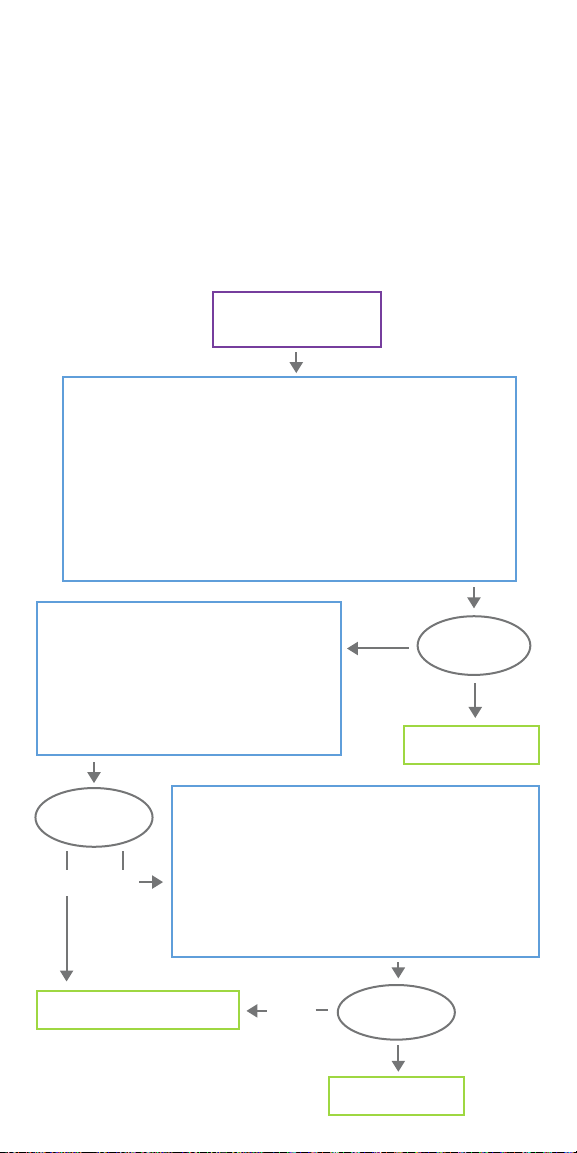
High/Low Lead Impedance and
Low Output Current Issues
HIGH LEAD IMPEDANCE IN THE OR
If a System Diagnostics test results in high lead impedance, the following are
possible causes:
• Improper connection between the lead and the generator
• Incorrect placement of lead on the nerve (initial implant only)
• Allowing nerve to become dry (initial implant only)
• Defective lead or generator
Error Message
Lead Impedance “HIGH”
Verify Lead Insertion into Generator
• Back out setscrew(s), remove lead pin(s), and leave the hex screwdriver engaged in
setscrew(s)
• Verify the setscrew(s) is not visible in the lead receptacle(s)
• Insert connector pin(s) and tighten setscrew(s) until the hex screwdriver clicks
• Confirm the lead pin(s) is past the back end of the connector block
• For single-pin generators, verify the end of the connector ring is inside of the lead
receptacle
• For Initial Implant: Irrigate dry nerve site and remove pooled fluid if necessary
• Verify proper lead electrode placement on the nerve
• Retry System Diagnostics
Troubleshoot Generator
• Back out setscrew(s) and remove lead pin(s)
• Insert test resistor into generator and tighten
setscrew(s) with hex screwdriver until the
screwdriver clicks
• Select MORE TROUBLESHOOTING on the programmer
• Select GENERATOR DIAGNOSTICS - START on the
programmer
“High”
Lead Impedance
Value?
“Ok”
Proceed with implant
Lead Impedance
Value?
“Ok”“High”
Contact LivaNova Technical Support
Reinsert Lead into Generator
• Back out setscrew(s) and remove test resistor
• Verify the setscrew(s) is not visible in the lead receptacle(s)
• Engage the hex screwdriver in the setscrew(s)
• Insert connector pin(s) and tighten setscrew(s) until the hex
screwdriver clicks
• Visually inspect the lead receptacle(s) and verify that the lead
pin(s) is past the back end of the connector block(s)
• Retry System Diagnostics
“High”
Lead Impedance
Value?
“Ok”
Proceed with implant
74

LOW LEAD IMPEDANCE IN THE OR
If a System Diagnostics test results in low lead impedance, the following are
possible causes:
• Incorrect placement of the lead on the nerve
• Excessive irrigation of the nerve
• Defective generator or lead
• Short-circuit condition within the lead (during generator replacement
surgery)
Error Message
“Lead Impedance “LOW”
Initial implant
Check the Lead
• Verify lead electrodes have been
correctly placed on the nerve
• Remove pooled fluid if nerve site
is saturated
• Retry System Diagnostics
Lead Impedance
Value?
“OK”
Proceed with implant
Initial implant
Reinsert Lead into Generator
• Back out setscrew(s) and remove test resistor
• Verify the setscrew(s) is not visible in the lead receptacle(s)
• Engage the hex screwdriver in the setscrew(s)
• Insert connector pin(s) and tighten setscrew(s) until the hex
screwdriver clicks
• Visually inspect the lead receptacle(s) and verify that the lead
pin(s) is past the back end of the connector block(s)
• Retry System Diagnostics
Type of
Implant?
Troubleshoot Generator
• Back out setscrew(s) and remove lead pin(s)
• Insert test resistor into generator and tighten
setscrew(s) with hex screwdriver until the
screwdriver clicks
• Select MORE TROUBLESHOOTING on the
programmer
• Select GENERATOR DIAGNOSTICS - START on
the programmer
“Low”
“OK”
Type of
implant?
Contact LivaNova Technical Support
Generator replacement
Generator replacement
Lead Impedance
Value?
“Low”
“Low”
Lead Impedance
Value?
“OK”
Proceed with implant
75

HIGH/LOW LEAD IMPEDANCE OR LOW OUTPUT CURRENT AT
FOLLOW-UP VISIT
Possible causes for high or low lead impedance or low output current at
follow-up visits for the model 1000 generator include the following:
• Lead discontinuity
• Lead disconnected from generator
• Fibrosis between nerve and electrode
• Electrode detachment from nerve
• Defective generator
• Short-circuit condition within the lead
Error Message
“A LOW Lead Impedance
has been detected...”
Lead Impedance “LOW”
System Diagnostics
Values
Lead Impedance
“HIGH”
Output Current
“OK”
Possible Causes:
• Lead discontinuity
• Lead disconnection
from the generator
• Fibrosis between the
nerve and electrode
• Electrode
detachment from
the nerve
• Defective generator
Error Message
“A HIGH Lead Impedance
has been detected...”
Lead Impedance “HIGH”
• Perform a Systems Diagnostics
• Record results
Lead Impedance “OK”
Output Current “OK”
Lead Impedance
“HIGH”
Output Current
“LOW”
Possible Causes:
• Lead discontinuity
• Lead disconnection
from the generator
• Fibrosis between the
nerve and electrode
• Electrode
detachment from
the nerve
• Defective generator
Lead Impedance
“OK”
Output Current
“LOW”
Possible Causes:
• Increased
impedance in the
system
Error Message
“Programmed current
is possibly not being
delivered...”
Output Current “LOW”
Generator is delivering
stimulation as intended
Lead Impedance
“LOW”
Output Current
“OK”
Possible Causes:
• Short-circuit
condition within
the lead
• Defective generator
Contact LivaNova Technical Support
76
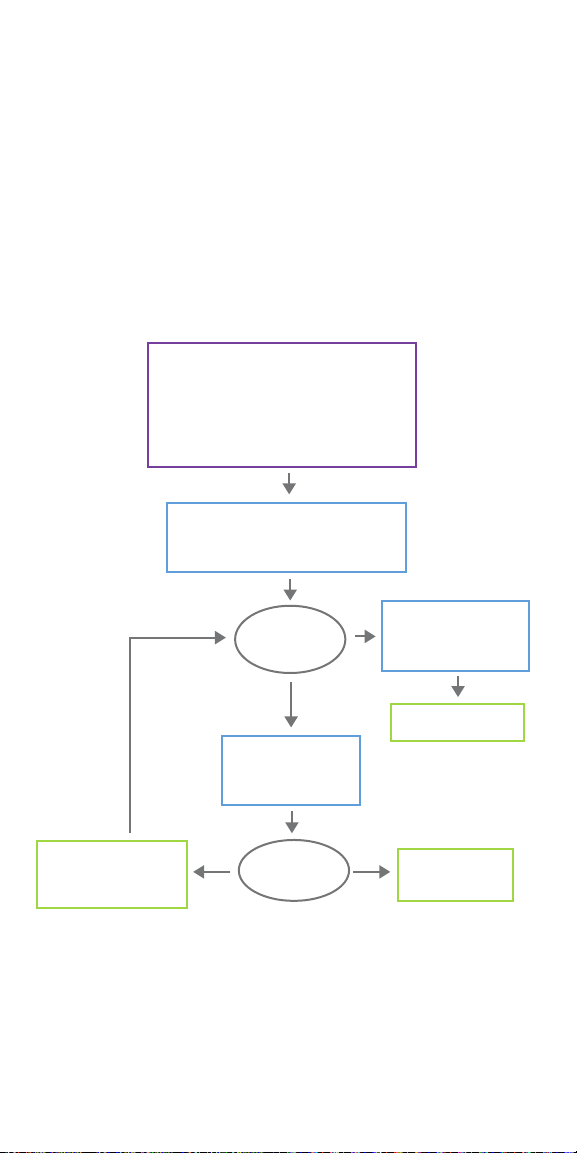
Generator Battery Issues
LOW BATTERY/END OF SERVICE INDICATIONS IN OR
If a generator displays a low battery or End of Service (EOS) indicator while
implanting, the possible causes include the following:
Prior to Surgery:
• Generator has been recently
exposed to low storage
temperatures
• Defective generator
• “Generator Battery N EOS…”
• “Generator Battery EOS…”
• “Frequent monitoring recommended.
The Intensified Followup Indicator (IFI) is set…”
• “Generator disabled…”
• Perform System Diagnostics or Generator
Diagnostics with device in sterile package
• Record results
During Surgery:
• Electrosurgical equipment used near
the generator
• Generator exposed to electrostatic
discharge (ESD)
Error Message
Diagnostic
Results
Same battery status
indicator or warning
message as above
• Lead Impedance “any”
• Impedance Value “any”
• IFI = No
Proceed with implant
Wait approximately
30 minutes with generator
at room temperature
1 2
Number of
attempts
Contact LivaNova
Technical Support
77

NEW GENERATOR DISABLED DUE TO EOS AT FIRST OFFICE VISIT
Generator model 1000 battery can temporarily drain and become disabled if
exposed to certain conditions. These conditions include the following:
• Electrosurgical equipment used near the generator
• Generator exposed to electrostatic discharge (ESD)
Error Message
“Generator is currently disabled...”
“IFI” = No “IFI” = Yes
Proceed with
intended use
Monitor patient for low
battery indicators
Note: Battery life will be
shortened
Enable Stimulation and Check System
• Select OK
• Enter desired parameters
• Select Apply Changes
• Perform System Diagnostics Test
Battery
Status?
All Other Errors
Contact LivaNova
Technical Support
“N EOS”=Yes or
immediately
“EOS”=Yes
Replace
Generator
SUDDEN DECREASE IN REMAINING BATTERY POWER
If the remaining generator battery power suddenly decreases at an oce visit,
the following are possible causes:
• First visit after VNS or other surgery: exposure to specific conditions in the
OR (see Low Battery/ End of Service Indications in OR) during surgery. If
this condition occurred and was not detected in the OR, it is possible you
may detect this at the follow up visit. Device will still function normally,
but will have decreased battery life. Monitor the patient closely for any low
battery indicators.
• Significant change in the lead impedance or increase in programmed
stimulation parameters can also result in a change in the estimated battery
power remaining. Evaluate battery power remaining between consecutive
patient visits before adjusting stimulation parameters.
• Review lead impedance for any significant changes.
If any device issue is suspected, contact LivaNova Technical Support.
78
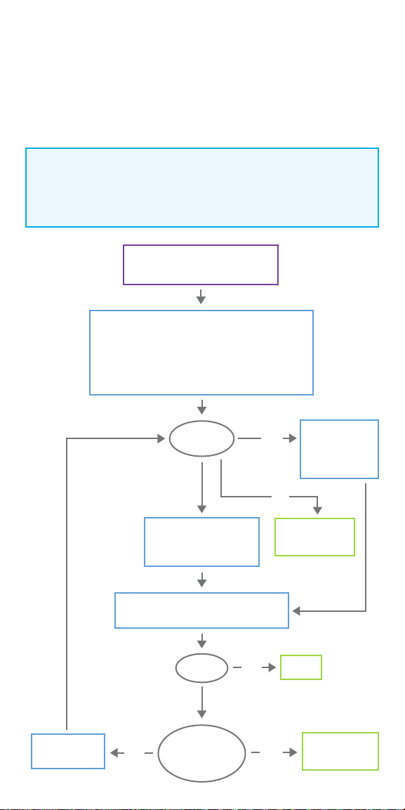
Heartbeat Detection Issues
HEARTBEAT DETECTION INACCURATE (OVER/UNDER) IN OR OR AT
FOLLOW-UP VISIT
The heartbeat detection setting may need to be adjusted to accurately
detect heartbeats.
NOTE:
The Wand must be held over the generator during the entire Verify
Heartbeat Detection process.
Heartbeat Detection is inaccurate
BPM is too high, low, or reports “??”
Check Hardware
• Confirm the programmer is not plugged into a wall outlet
Check Software
• Confirm Detection is enabled
Check Wand Placement
• Verify wand is over the generator
Retry with
dierent settings
BPM?
High
Adjust Heartbeat Detection
setting downward
(toward “1”)
Confirm accuracy in dierent body positions
(e.g. o-the-shelf heart rate monitor)
Ok?
No
No
All settings
attempted with
out success?
Low
Yes
Yes
Adjust Heartbeat
Detection
setting upward
(toward “5”)
??
Contact LivaNova
Technical Support
Done
Contact LivaNova
Technical Support
79

Tachycardia Detection Issues
INACCURATE AUTOSTIMS AT FOLLOW-UP VISIT
Sometimes generator detection settings may miss detecting heart rate changes
that may be associated with a seizure. The following conditions may be
potential causes:
Duty cycle
Because the generator can only
detect events during OFF time, the
OFF time aects accuracy. Shorter
OFF time means less chance for the
generator to detect events. Longer
OFF time, on the other hand, means
more chance for the generator to
detect events.
Too many or too few AutoStims
Confirm Heartbeat Detection settings (See Solution Steps for
Heartbeat Detection Inaccurate in OR or at Follow-up Visit)
Too many
Adjust Threshold for
AutoStim setting
toward 70%
Heart rate changes
Exercise, physical activity, and normal
sleep can increase the heart rate and
cause the generator to falsely declare
an event.
Number
of AutoStims
Too few
Adjust Threshold for
AutoStim setting
toward 20%
Yes
Contact LivaNova
Technical Support
Monitor accuracy over
course of therapy
Still Inaccurate
after several
adjustments?
No
Continue with
programmed setting
80

LivaNova USA, Inc.
100 Cyberonics Boulevard
Houston, Texas 77058
Tel: +1.800.332.1375
Fax: +1.281.218.9332
www.VNSTherapy.com
LivaNova Belgium NV
Ikaroslaan 83
1930 Zaventem
Belgium
Tel: +32.2.720.95.93
Fax: +32.2.720.60.53
©2019 LivaNova USA, Inc, a
wholly-owned subsidiary of
LivaNova PLC. All rights reserved.
LivaNova®, SenTiva®, AspireSR®
and VNS Therapy® are registered
trademarks of LivaNova USA, Inc.
SenTecGd19U1
81
 Loading...