

VNS CCTV High Speed Dome Camera User Manual

High Speed Dome Camera
User’s Manual
●
Please read the manual carefully before installing and using the unit.
●

- 2 -
Table of Contents
I. Introduction
----------------------------------------------------------------------------------------5
II. Technical Data
-----------------------------------------------------------------------------------6
III. Characteristics
----------------------------------------------------------------------------------7
IV. Description of Functions
------------------------------------------------------------------8
V. Installation and Connection of the System
----------------------------------- 13
5.1 Outer-shape and Dimension of Wall-mount and Pendant-mount High-speed
Dome Camera----------------------------------------------------------------------------------13
5.2 Outer-shape and Dimension of Ceiling-mount High-speed Dome Camera ------13
5.3 Outer-shape and Dimension of In-ceiling-mount High-speed Dome Camera
------------------------------------------------------------------------------------------------------------14
5.4 Preparation for the installation---------------------------------------------------------------15
5.5 Installation of Wall-mount High Speed Dome Camera--------------------------------17
5.6 Installation of Pendant-mount High Speed Dome Camera---------------------------22
5.7 Installation of Ceiling-mount High Speed Dome Camera-----------------------------25
5.8 Installation of In-ceiling-mount High Speed Dome Camera--------------------------28
5.9 Connection and Installation of Alarm-------------------------------------------------------31

- 3 -
VI. Configure the system of the High Speed Dome Camera
-----------33
6.1 Configure Communication Protocol, Address and Baudrate of High Speed
Dome Camera -------------------------------------------------------------------------------------33
6.2 Table for the functions that can be configured or operated directly through the
keyboard ---------------------------------------------------------------------------------------------35
VII. Configuration and operation through the OSD Menu
----------------37
7.1 Basic Operation-------------------------------------------------------------------------------37
7.2 Table for all Configuration and Operations through OSD Menu------------------38
7.3 Configure the information of the system -----------------------------------------------41
7.4 Configure the parameter of the camera module--------------------------------------52
7.5 Configuration of Auto Running------------------------------------------------------------67
7.6 Configuration of Alarm function-----------------------------------------------------------76
VIII. Simple Trouble Shooting Table
---------------------------------------------------79
VIV. Correspondence of Address and Coding Switches
------------------80

- 4 -
Important Safeguards
1. During the course of transportation and storage, the product should be
avoided from incorrect operations such as heavy pressing, strong
vibration, soaking etc, which may cause damage to the unit.
2. The product is designed for Pendant or Wall Mount installation, so it
can not be installed upside-down. And the module should be handled
properly so as not to bring about mechanical problems affecting the
integrative functions of it. The vitreous cover of the speed dome is
complicated optical component, so do not touch it with bare hand(s).
Otherwise, the cover might be scraped, and image quality affected.
3. Do not let any foreign objects or liquid infiltrate into the unit, which may
damage the machine.
4. Please follow all electrical standards for safety when it is being
connected and please adopt the particular power supply which is
provided with the unit. The product’s RS-485 and video signal adopt
TVS-class lightning damage preventing technology, which can
effectively prevent such pulse signal damage caused by lightning
under 500W or electric surge. RS-485 and video signal should be
kept enough distance from high voltage equipments and cables
when they are in transmission, and necessary steps should be
taken to prevent lightning damage or power surge.
5. No matter the unit is running or not, the camera module should never
be aimed at the sun or object with extremely bright light. Otherwise, the
camera module’s CCD might be permanently damaged.
6. There are no parts inside the unit which can be repaired by the users
themselves. When mechanical problems arise, do not be in a haste to do
any repairing, please refer to the User’s Manual to find the trouble. If
causes can not be located, please refer servicing to qualified
professionals. All servicing must be done by authorized personnel.

- 5 -
I. Introduction
Adopting latest technological achievements and cutting-edge
manufacturing techniques, the High Speed Dome Camera is created with
many years of accumulated experience. Equiped with a high
performance DSP camera module with zooming lens, integrating built-in
Pan/tilt and digital decoder, it represents the future trend of hi-tech
monitoring products. The unit is capable of rapid positioning,
consecutively tracing and scanning, which realizes real all-directional
monitoring. The unit can automatically adapt to ambient brightness and
object distance. Its digital control and elegantly simple design maximally
reduces the connection between differnent parts in the system, which
improves the reliability of the system and facilitate the installation and
maintenance. Driven by a stepper electric motar, the unit runs smoothly,
reacts quickly and locates positions accurately. At the same time, the unit
has multiple intelligent functions such as: left & right scan, pattern scan,
tour, alarm function etc.
Based on the above characters of common High Speed Dome Camera,
this type of High Speed Dome Camera is further equiped with OSD menu
operation interface with multi Input Modes, which further facilitates all
kinds of operations.
With varieties of high-performances, this type of High Speed Dome
Camera can be applied in every walk of life to monitor moving objects in
large areas, such as monitoring smart buildings, bank, city streets, power
departments, airports, bus/railway stations etc.

- 6 -
II. Technical Data
Power supply DC15V(1.5A)
Working temperature outdoor:(-25~+65)
Relative humidity ≤95%
Power consumption 20W
Communication system RS485 bus
Baud rate of communication 1200 / 2400 / 4800 / 9600bps
Address Range 1~255
Manual Pan Speed 0.5º-200º/s(64 ranges)
Highest Cruising Speed 350º/s
Pan movement 360º endless
Tilt movement 0~90º
Automatic flip Automatic 180º flip when vertical 90º
Speed Auto-control as per
the changing of focal length
The speed dome can automatically adjust the running
speed following the change of the focal length.
OSD menu
4 input modes, all the functions of the pan/tilt and the
camera module can be oprated through the menu.
Preset position number 128
Left & right scan Yes
Tour group
4 groups/16 preset positions for each group/dwelling
time at each preset position can be configured in the
range of 1-255s
Pattern Scan number 4
Idle Time function
The function to be carried out in idle time can be
configured including invoking preset position, left & right
scan, tour etc.
Alarm function 4 channels in/1channel out
Protection Grade IP66
Weight 4.75Kg (Bracket included)

- 7 -
III. Characteristics
The unit is equipped with a camera programme which can
automatically identify 8 brands of camera modules: HITACHI, SONY,
LG, CANON, SAMSUNG, KT&C, CNB and JCO.
Adopting multi-functional high-performance DSP design with stable
performance
Integrated design with compact structure and high reliability
Precise electric motor drive ensuring smooth running and agile
reaction
Internally-saved data will not lose within one year after power off.
OSD menu function, facilitates the user to directly and conveniently
configure the parameters and run the functions of the unit.
128 preset positions for freely storage and accurate locating
4 tour groups, 16 preset positions can be configure for each group.
Support left&right scan function, the scanning speed can be
configured at low, medium or high three levels.
4 pattern scans
Support idle time function, multi-functions can be configured to be
carried out in idle time
Pan 360° consecutive movement, all-direction monitoring
With the auto-flip function, tilt 180° consecutive monitoring realized
Alarm: 4 channels in/1channel out
Automatically adjusting moving speed according to the zoom ratio
of the lens
Auto Iris, Focus and White Balance

- 8 -
IV. Description of Functions
1. OSD Menu Operation
The functions of the pan/tilt and the built-in camera module can be
conveniently configured and carried out through the OSD menu. These
functions include: Preset Positions, Tours, Pattern Scan, Left & Right
Scan, Alarm, Language Choosing, and the configuration of the
parameters of the Camera Module etc.
2. Trace the Target
The users can control the movement of the unit by operating the joystick
of the keyboard so that they can trace the moving object or change the
monitoring area. The angle of view or the size of the image of the object
can be changed through adjusting the focal length. In the default
Auto-focus, Auto-Iris state, following the movement of the unit, the lens
will quickly adjust itself to get clear image according to the change of the
object.
3. Automatic Adjustment of Focal Length/Movement Speed
When the focus is long and in the mode of manual adjustment, due to the
high sensitivity of the speed dome, even the slightest movement of the
joystick would make the image move quickly, which causes image losses.
Based on human design, the speed dome can automatically adjust the
horizontal and vertical moving speed of the pan/tilt according to the
current focal-length, which makes the manual target-tracing operation
much easier.
4. Automatic Flip
In the process of operating the joystick to trace and monitor, if the user
move the lens to the bottom(vertical) then continues pressing the joystick,

- 9 -
the lens will automatically flip 180º horizontally, then the user can still
control it to move upwards till 90°, which enables the user to directly
observe the situation on the back side, thus tilt 180° consecutive
monitoring can be realized.
5. Configure and Invoke Preset Positions
The preset position function works in this way: the speed dome stores
the data of the pan/tilt angles and lens focal-length in current state; when
needed, invoke these data, then promptly move the pan/tilt and camera
module to the corresponding position. Through the OSD menu, the user
can quickly and conveniently configure, invoke, delete the preset
positions and compile the title of the preset positions. When the user
invokes the preset position through the OSD menu, the unit will move to
the preset position promptly, at the same time, the title of the preset
positon compiled by the user will be shown. The unit supports 128 preset
positions.
6. Automatic Tours
The automatic tour function is a built-in function of the speed dome
camera. Through beforehand programming, the user can arrange the
preset positions into the automatic tour in the desired order. When it’s
needed to run the tour, operating through the OSD menu, the user can
make the speed dome camera automatically move as per the order of the
preset positions configured in the tour with preset time intervals.
● The staying time at each preset position can be configured.
● Altogether 4 tours can be configured with the unit.
● Sixteen preset positions can be stored in one tour.
7. Left & right Scan
Left/right limiting positions can be conveniently configured through OSD

- 10 -
menu. After configuring well, the user can run the left/right scan directly
through the OSD menu, then the speed dome will automatically run
horizontally between the left limiting position and the right limiting
position, at the preset speed.
8. Pattern Scan
The unit can store the user’s operating track and invoke it when
necessary. A 4-minutes operation is acceptable to be stored for one
Pattern Scan track. Altogether 4 Pattern Scan tracks can be stored in this
unit.
9. Alarm Function
The user can set the key areas as alarm points. Through the linkage with
the external-connected detector, once there is alarm signal transmitted to
the unit, the unit will promptly adjust the camera module to shoot the
alarm point, at the same time, it will output alarm signal through the alarm
output port. Considering that the channels that can be contained with
wire alarm is so less, users can also choose our latest-developed
wireless alarm, wireless alarm can support 16 channels in, 16 chanels
out.
10. Idle Time Function
Users can configure the function that is to be carried out in idle time as
the Idle Time Function. If the user exit the OSD menu after finishing with
other operations, and if the speed dome is in still state without running,
then after a period of time during which nobody operates the unit, the unit
will automatically begin to carry out Idle Time Function that is configured
in advance. The functions that can be configured as Idle Time Function
include invoking preset position, running left&right scan, running tour etc.
The length of the period of time after which the Idle Time Function is to

- 11 -
be carried out can be configured, the range is 1~240minutes.
11. Camera module Lens Control
Users can adjust the Focal-length through controlling the keyboard to get
panoramic view or close view that they desire.
Focal Length Control
Users can adjust the Focal-length through controlling the keyboard to get
panoramic view or close view that they desire.
Focus Control
The system takes automatic focus as the default. While moving, the
camera module can automatically focus on the center of the object view
to get clear image. Under special circumstances, the user can manually
adjust the focus to achieve desired image effect.
● Manual focus can be realized through controlling the keyboard or
matrix. For details, please refer to the operation manual of the controlling
keyboard or matrix.
● In the state of manual focus, the user can control focal–length to make
the lens focus on objects. If the speed dome camera is configured to
resume auto-focus upon joystick operation, when there is operating on
the joystick, the speed dome camera will automatically focus. If a period
of time is configured for auto-focus resuming, once there is no controlling
order received, after the period of time, the speed dome camera will
resume auto-focus.
Under the following circumstances, the camera module can not
carry out auto-focus:
● When the object is not in the center of the view.
● When simultaneously observe a far object and a near one, clarity for
both of the images can not be guaranteed at the same time.
● When observing objects with extreme brightness, such as neon lights,

- 12 -
spotlight, etc
● When the object is behind the glass with water drops or dust
● When the object moves very fast
● When the object is large-sized and drab, such as wall
● When the object is too dark or fuzzy
Iris Control
● The system takes automatic-iris as the default. The iris can
automatically sense the change of the environmental light and make
quick adjustment, so that the brightness of the image is stable.
● The user can manually adjust the iris through controlling the keyboard
to obtain desired brightness for the image.
Automatic Back Light Compensation (BLC)
Automatic Back Light Compensation can be realized via district dividing.
In extremely bright background, the camera module can compensate the
brightness of the relatively dark objects, while adjust the light of the bright
background, avoiding that the whole image is too bright to watch due to
the too high brightness of the background while the object is too dark to
be distinguished, so that clear image can be got.
Automatic White Balance
According to the ambient brightness, the camera module can
automatically adjust the White Balance to re-display the real colors.
- 13 -
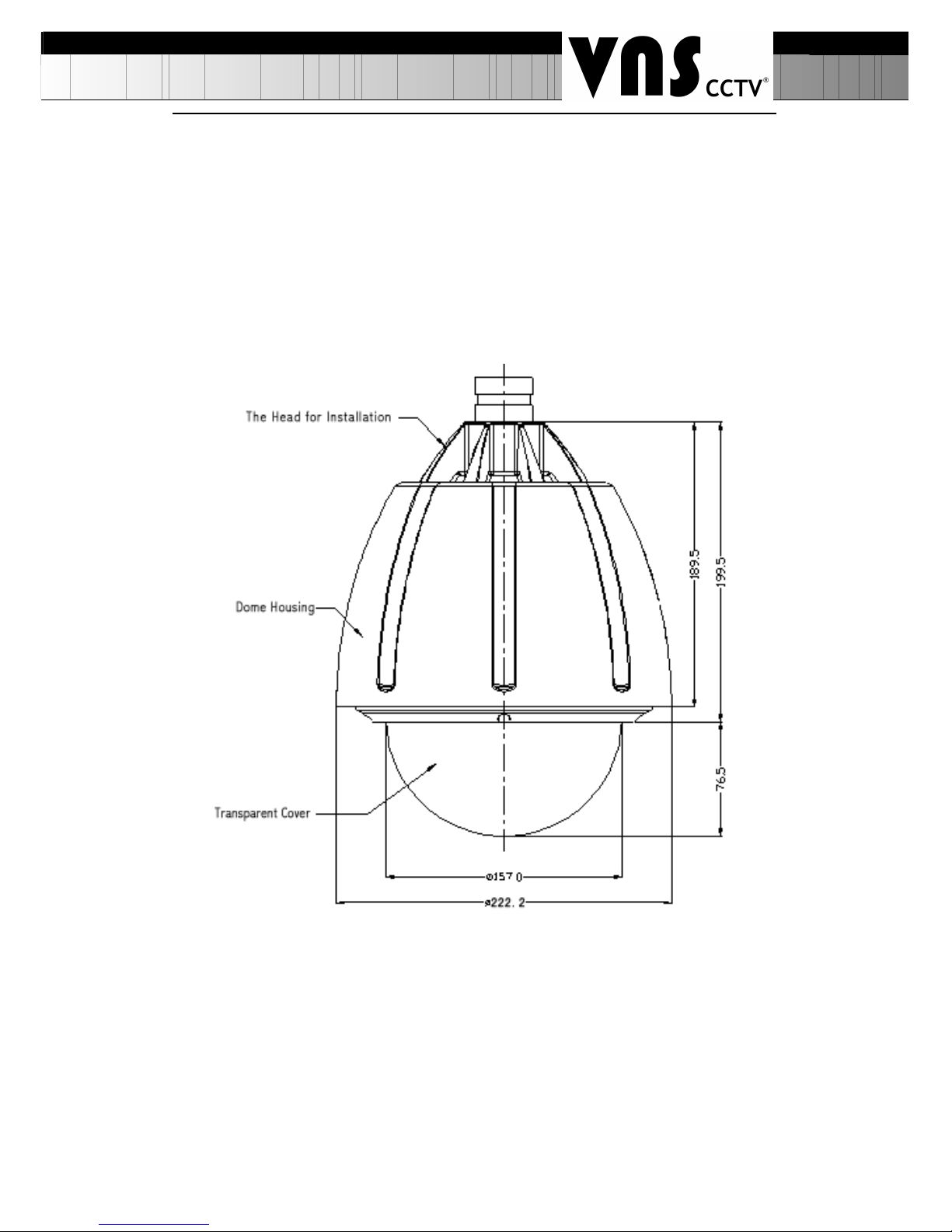
V. Installation and Connection of the System
There are three types of installation for high speed dome cameras, the
dimensions are shown below:
5.1 The outer-shape and dimension of Wall-mount,
Pendant-mount High-speed Dome Camera
5.2 The outer-shape and dimension of Ceiling-mount
High-speed Dome Camera
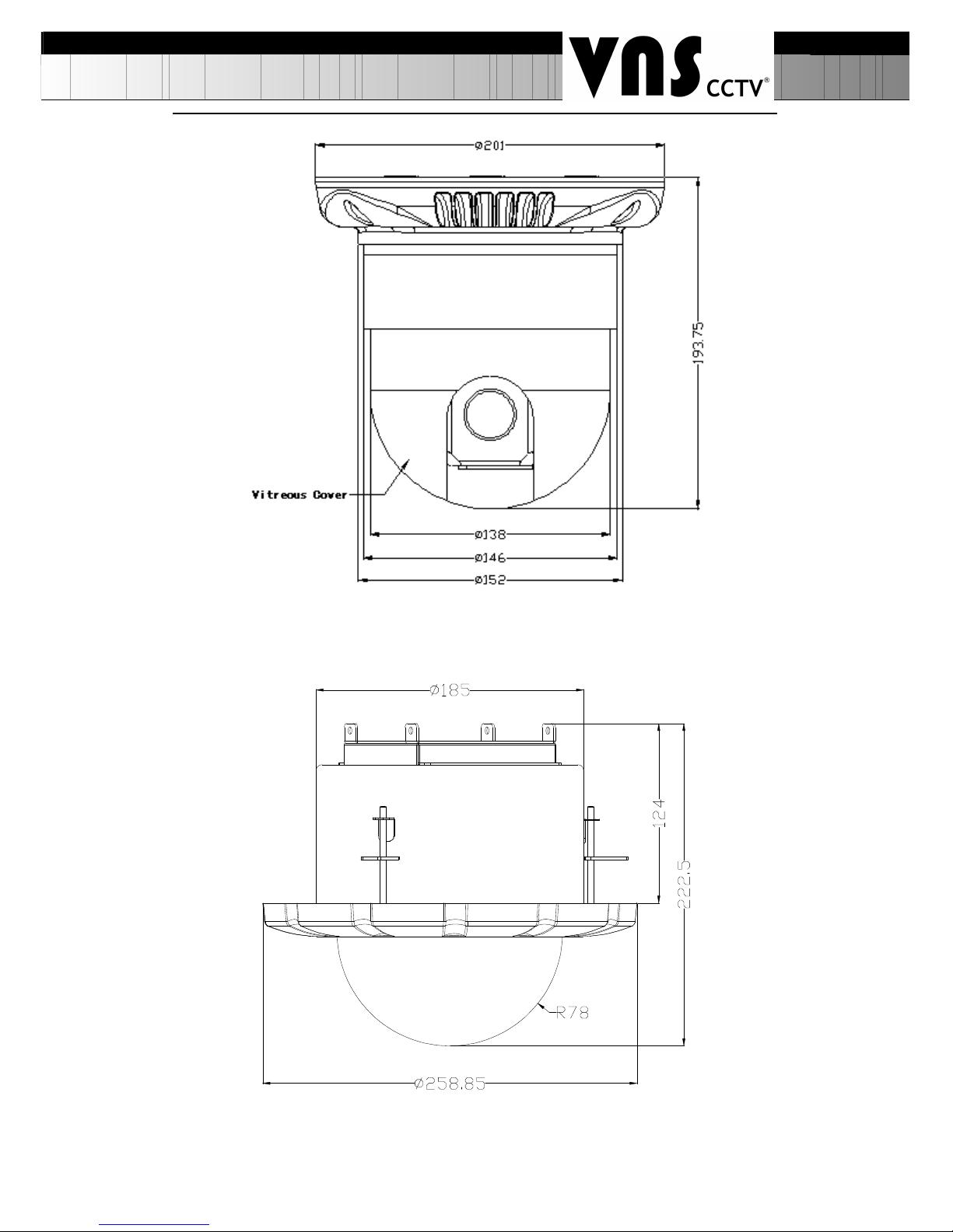
- 14 -
5.3 The outer-shape and dimension of In-ceiling-mount
High-speed Dome Camera
- 15 -
·Installation Style and Ancillary Components
Products
Installation Style
Bracket Cable (with connector)
High
Speed
Dome
Camera
Wall-mount Wall bracket
Power Cable 1pc
Video cable 1pc
485 cable 1pc
Lightening-proof cable 1pc
5-strands cable 1pc (Alarm input)
2-strands cable 1pc (Alarm output)
Pendant-mount
Bracket with the length
of 20cm or 40cm
Ceiling-mount No bracket
In-ceiling mount No bracket
Remarks:
1. The connection must be carried out by qualified personnel
conforming to local regulations.
2. For connection details, please refer to the silk-screen printing
indications and installation instructions on the PCB board.
3. The vitreous cover of the unit is complicated optical component, so
do not touch it with bare hand(s). Otherwise, the cover might be scraped,
and image quality affected.
4. To ensure the clarity of images, please clean the vitreous cover
regularly. Be careful when cleaning it. You can only hold the outer ring of
the vitreous cover. Do not touch it with bare hand(s), for acid sweat left
may erode the surface plating of the vitreous cover, or hard things may
scrape the vitreous cover leading to fuzzy image and, hence, affecting
image quality. Please use adequately soft dry cloth or other substitutes to
clean the inner and outer surfaces. If the vitreous cover is extremely dirty,
it may be cleaned with mild detergent.
5.4 Preparation for the Installation:
· To avoid mistakes, installation must be carried out by qualified

- 16 -
personnel conforming to related regulations.
· Please check whether the attachments are all ready, and whether the
installing location and style of installation are compatible.
· The wall-mount and the pendant-mount high speed dome camera is
composed of bracket, housings, power supply, decoding board, pan/tilt,
temperature controlling devices, etc. Well, the ceiling-mount high speed
dome camera is composed of ceiling installing board, ceiling-mount
decorating cover, housings, power supply, decoding board, pan/tilt etc.
· When the speed dome camera leaves factory, it has undergone
installation testing, so the user can directly carry out the installation.
· For wall-mount and pendant-mount high speed dome, before
installation, the user should open the vitreous cover and make sure the
screws are tight and cable connectors not loose.
The sketch for the Installation of the Module into the Housing of the
wall-mount or pendant-mount high speed dome:
Locate the three installing slots at the bottom of the module into the three
pegs on the housing peg-board (be sure in right direction), and lock them
in place then swivel the module right for 20°, to the point where the
screw-fixing hole in the module meets the corresponding stud. Finally, fix

- 17 -
the module with the housing with M3 screw and make sure it is tight.
Attention: The adaptor equiped can only be placed indoor or in
water-proof box or other water-proof spaces, it can not be placed directly
outdoor, otherwise water may seep in and damage the adaptor.
5.5 Installation of Wall-mount High-speed Dome Camera
5.5.1 Installation of Wall-mount Bracket
Attention:
The wall for the selected installation location must be firm without peeling.
To avoid quivering images resulting from unstable installation, make sure
the place for installation can sustain five times the total weight of the
speed dome camera and the bracket.
A. Use the bottom installation board of the bracket as template and
draw the positions of the installing holes on the desired wall locus;
Wall Bracket Installation Dimensions

- 18 -
B. Use an electrical drill to make four holes for M6 screws on the
above-drawn positions, and drive in the expansion M6 screws;
C. Push the power cable, communication cable and video cable
through the bracket tube, leaving long enough cables for connection;
D. Fix the installation board of the bracket firmly on the wall with four
M6 screw nuts and washers.
E. Put the power adaptor into the wall bracket and pin the power
adaptor with the power pinning board, lest the power adaptor slides out.
(See the figure below)
F. Fix the high speed dome with the wall bracket. (refer to the detailed
explanation in the next page)
G. Put up the wall bracket assembled with high speed dome on the
ancillary hooks. Pull the power cable, video cable and controlling cable
out through the wire out-going hole, and direct the dotted-line part shown
in the figure to the two corresponding pegs on the installed peg-board,
then push the bracket downwards until it locks in place. Make sure the
wall bracket is well fixed with the installation board, then direct the screw
on the bracket to the corresponding hole on the lower part of the
installation board and tighten the screw. (See the figure below)

- 19 -
5.5.2 Installation of High Speed Dome Camera
a. Unpack the carton and carefully take out the speed dome camera and
its attachments, open the vitreous cover and take out the fillings.
b. Check cable connectors and see if any of them loose and configure
the coding switch.
c. Put the connecting cables into the bracket tube, then push the
installing port on the top of the outer housing into the installing hole of the
bracket, tighten the 3 M6 screws and fix well. Make sure the M6 screws
just fit in the screw slot of the installing port of the housing. (See the
picture below).

- 20 -
5.5.3 Connection of Exterior Cables
Connect BNC video outlet of the unit with the already disposed video
cable, the power cable with the already disposed power cable and
RS485 controlling cable with already disposed RS485 controlling cable.
The cables of high speed dome camera is shown below:
Cable Application Connecting Objects Remarks
7-strand
cable
power supply high speed dome---
power supply adaptor
Power supply connecting outlet
RS485 cable high speed dome---
controlling device
Green (A), white(B)
Video cable Camera module---
monitoring device
BNC connector
Lightening proof High speed dome ---
the earth
Grey

- 21 -
5-strand
cable
Alarm input Detector ----
high speed dome
Black (Alarm input public terminal)
Yellow (the 1st channel alarm input)
Green (the 2nd channel alarm input)
Blue (the 3rd channel alarm input)
White (the 4th channel alarm input)
2-strand
cable
Alarm output High speed dome---
alarm horn
Brown (alarm output public terminal)
Grey (alarm output terminal)
Make sure the polarity of RS485 controlling cable connection is
correct, A: RS485 positive, B: RS485 negative.
If wrongly connected, the speed dome camera will be out of control.
The detailed connection as the sketch below:
5.5.4 Switch on Power
a. Make sure the polarity of plugs, sockets and cables connection is
correct, then switch on power
b. The speed dome camera begins to do the self-check by moving pan
360°, tilt 90° to check the camera lens, the electr ical and mechanical
structures in pan/tilt state, then executing the restoration program and
resuming its original position. After the unit stops moving, it finishes

- 22 -
self-check and is ready to receive controlling instructions
c. Use controlling device to control the unit, checking whether it can
perform the functions of the pan/tilt and camera lens. If not, please check
the configuration of communication protocol, Baud rate and address, and
the connection of 485 controlling cable.
5.5.5 Vitreous Cover Installation
a. Clean the dust and stain on the vitreous cover with soft cloth, attention
not to scrape the vitreous cover;
b. Aim the four special bolts (the bolts don’t fall even if they are loosened
to the extreme) in the vitreous cover at the bolts holes in the outer
housing, then tighten the bolts.
5.6 Installation of Pendant-mount High Speed Dome
5.6.1 Installation of Pendant-mount Bracket
Attention:The ceiling for the selected installation location must be firm
without peeling. To avoid quivering images resulting from unstable
installation, make sure the place for installation can sustain five times the
total weight of the speed dome camera and the bracket.
a. Use the bracket as template and draw the positions of the installing
holes on the desired ceiling locus;
b. Use an electric drill to make three holes for M6 screws on the
above-drawn positions, and drive in the special M6 screws;
c. Push the power cable, communication cable and video cable through
the bracket tube, leaving long enough cables for connection;
d. Fix the bracket firmly on the ceiling with three M6 screw nuts and
washers.

- 23 -
5.6.2 Installation of High Speed Dome Camera
a. Unpack the carton and carefully take out the speed dome camera and
its attachments, open the vitreous cover and take out the fillings.
b. Check cable connectors and see if any of them loose and configure
the coding switch.
c. Put the connecting cables into the bracket tube, then push the
installing port on the top of the outer housing into the installing hole of the
bracket, tighten the 3 M6 screws and fix well. Make sure the M6 screws
just fit in the screw slot of the installing port of the housing.
5.6.3 Connection of Exterior Cables
Connect BNC video outlet of the unit with the already disposed video
cable, the power cable with the already disposed power cable and
RS485 controlling cable with already disposed RS485 controlling cable.
The cables of high speed dome camera is shown below:
Cable Application Connecting Objects Remarks
7-strand
cable
power supply high speed dome---
power supply adaptor
Power supply connecting outlet
RS485 cable high speed dome---
controlling device
Green (A), white(B)

- 24 -
Video cable Camera module---
monitoring device
BNC connector
Lightening
proof
High speed dome --the earth
Grey
5-strand
cable
Alarm input Detector ----
high speed dome
Black (Alarm input public terminal)
Yellow (the 1st channel alarm input)
Green (the 2nd channel alarm input)
Blue (the 3rd channel alarm input)
White (the 4th channel alarm input)
2-strand
cable
Alarm output High speed dome---
alarm horn
Brown (alarm output public terminal)
Grey (alarm output terminal)
Make sure the polarity of RS485 controlling cable connection is
correct, A: RS485 positive, B: RS485 negative.
If wrongly connected, the speed dome camera will be out of control.
5.6.4 Switch on Power
a. Make sure the polarity of plugs, sockets and cables connection is
correct, then switch on power
b. The speed dome camera begins to do self-check by moving pan 360°,
tilt 90° to check the camera lens, the electrical and mechanical structures
in pan/tilt state, then executing the restoration program and resuming its
original position. After the speed dome camera stops moving, it finishes
self-check and is ready to receive controlling instructions
c. Use controlling device to control the speed dome camera, checking
whether it can perform the functions of the pan/tilt and camera lens. If not,
please check the configuration of communication protocol, Baud rate and
address, and the connection of 485 controlling cable.
5.6.5 Installation of the Vitreous Cover
a. Clean the dust and stain on the vitreous cover with soft cloth, attention

- 25 -
not to scrape the vitreous cover;
b. Aim the four special bolts (the bolts don’t fall even if they are loosened
to the extreme) in the vitreous cover at the bolts holes in the outer
housing, then tighten the bolts.
5.7 Installation of ceiling-mount high speed dome camera
5.7.1 Installation of ceiling-mount installation board
Attention:The ceiling for the selected installation location must be firm
without peeling. To avoid quivering images resulting from unstable
installation, make sure the place for installation can sustain five times the
weight of the speed dome camera.
a. Use the ceiling-mount installation board as template and draw the
positions of the three installing holes and the cable hole on the desired
ceiling locus;
b. Use an electric drill to make three Expansion screw holes for M6
screws on the above-drawn positions, and drive in the Expansion M6
screws;
c. Use an electric drill to make a cable hole with the diameter of 20mm on
the ceiling.
d. Push the power cable, communication cable and video cable through
the cable hole, leaving long enough cables for connection;
e. Fix the ceiling-mount installation board firmly on the ceiling with three
M6 screw nuts and washers.
 Loading...