

G406 User Guide Document: G406-3
------------------------------------------------------------------------------------------------------------------------------------------------
The absolute opposite of ordinary
G406 Quick User Guide
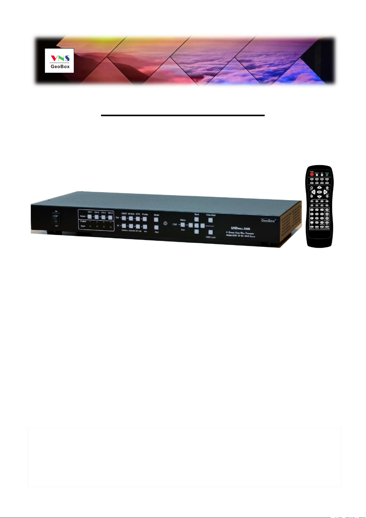
G406 4K/60 video wall controller
0

G406 User Guide Document: G406-3
------------------------------------------------------------------------------------------------------------------------------------------------
Table of Contents
Disclaimer/Copyright statement.............................................................................................................. 1
Warranty/RMA and FCC/CE statement.................................................................................................... 2
Introduction……………………………………………………………………………....................................... 3
Features...................................................................................................................................................... 3
Quick User Guide............................................................................................……................................... 4
Content in the packing box...................................................................................................................... 4
How to use IR Remote Controller............................................................................................................. 4
System Setup procedures......................................................................................................................... 5
1 Step 1 – Connecting the Inputs.........………………………………………….….................................. 5
2 Step 2 – Connecting the Outputs....................................................………….................................... 5
3 Step 3 – HDMI Loop Out for Multiple Units Connection..............……………….……………………. 6
4 Step 4 – System Connection and Power On.......……………………………………………………….. 7
5 Step 5 – Input Source / Output Resolution Selection & LED Lights.........………………………..... 8
6 Step 6 – Front Panel Keypad Operation.......................................................................................... 9
7 Step 7 – System Settings: Box ID, RS232, Ethernet........................................................................ 9
8 Step 8 – Conventional Video Wall Settings..................................................................................... 10
8.1 [Zoom] – Split Source Image.................................................................................................. 11
8.2 [Pan] – Assign Image Position............................................................................................... 11
8.3 [Overlap] –Position Alignment................................................................................................ 12
8.4 Bexel Compensation................................................................................................................ 12
9 Step 8 - Irregular / Asymmetric video wall setting.......................................................................... 12
9.1 Introduction............................................................................................................................... 12
9.2 Wind-Mill Asymmetric Video Wall Setup Procedures........................................................... 13
9.3 Square Asymmetric Video Wall Setup Procedures............................................................... 16
9.4 Other Big Scale Asymmetric Video Wall................................................................................ 19
10 Flexible Aspect Ratio Adjustment..................................................................................................... 23
11 Save System Settings through OSD Menu........................................................................................ 24
12 Save and backup settings through PC tool...................................................................................... 25
13 Load Profile Index through Front Panel hotkeys.............................................................................. 25
14 Load/Save Profile Index through Remote Controller........................................................................ 25
15 Helpful Tips for Video Wall Settings.................................................................................................. 25
16 Convenient Settings in Multiple Unit Application............................................................................ 26
16.1 Setup by Remote Controller.................................................................................................... 26
16.2 Setup by Ethernet..................................................................................................................... 26
16.2.1 WebGui............................................................................................................................. 26
16.2.2 UHDWall Manager (UWM) PC tool.................................................................................. 28
17 System Structure and Control........................................................................................................... 28
17.1 System Structure: Group A & Group B.................................................................................. 28
17.2 OSD Command Execution in Group A & Group B.................................................................. 28
1

G406 User Guide Document: G406-3
------------------------------------------------------------------------------------------------------------------------------------------------
17.3 EDID Setting.............................................................................................................................. 29
17.4 HDMI vs. DVI Output Signal..................................................................................................... 29
17.5 System Standby and Automatically Turn Off output Signal................................................. 30
17.6 RS232 Setting............................................................................................................................ 30
17.7 Ethernet Setting (Please see more details in Section 14.2)................................................. 30
17.8 Change Background Color...................................................................................................... 31
17.9 Change OSD Menu display time............................................................................................. 31
17.10 Change Splash screen logo display time............................................................................... 31
18 Limitations in Image Flip and Rotation............................................................................................. 31
19 Limitation in Audio Output................................................................................................................ 31
20 Trouble Shooting................................................................................................................................ 31
21 Technical Support............................................................................................................................... 32
22 Safety Precaution and Maintenance.................................................................................................. 33
Specifications.............................................................................................................................................. 34
Revision history........................................................................................................................................... 35
Disclaimer/Copyright Statement
Copyright 2018, VNS Inc. All Right Reserved
This information contained in this document is protected by copyright. All rights are reserved by VNS Inc.
VNS Inc. reserves the right to modify this document without any obligation to notify any person or entity of such revision.
Copying, duplicating, selling, or otherwise distributing any part of this document without signing a non-disclosure
agreement with an authorized representative of VNS Inc. is prohibited. VNS Inc. makes no warranty for the use of its
products and bears no responsibility for any error of omission that may appear in this document.
Product names mentioned herein are used for identification purposes only and may be trademarks of their respective
companies.
Limited Warranty and RMA statement
This device is designed and tested to the highest standards and backed by two years’ parts and labor warranty. Warranties
are effective upon the first delivery date to the end customer and are non-transferable. Warranty related repairs include
parts and labor, but do not include repair of faults resulting from user negligence, special modifications, abuse (mechanical
damage), shipping damage, and/or other unusual damages. The customer shall pay shipping charges when the unit is
returned for repair. Manufacturer will pay shipping charges for return shipments to customers.
Manufacturer does not assume responsibility for consequential damages, expenses or loss of revenue, inconvenience or
interruption in operation experienced by the customer. Warranty service shall not automatically extend the warranty period.
User can pay extension fee to extend the warranty period. Please contact us for more details. In the event that a product
needs to be returned for repair, inform manufacturer and ask for a Return Material Authorization number.
FCC/CE statement
This equipment has been tested and found to comply with the limits for a Class A digital device, pursuant to part 15 of the
FCC Rules. These limits are designed to provide reasonable protection against harmful interference when the equipment
is operated in a residential / commercial environment. This equipment generates, uses, and can radiate radio frequency
energy and, if not installed and used in accordance with the instruction manual, may cause harmful interference to radio
communications. Operation of this equipment in a residential area is likely to cause harmful interference in which case the
user will be required to correct the interference at his own expense.
2
G406 User Guide Document: G406-3
------------------------------------------------------------------------------------------------------------------------------------------------
Introduction
GeoBox G406 is new generation DCi/UHD 60fps four screens video wall controller to allow great freedom in
creating any scale video wall with multiple contents and different LCD arrays. It incorporates two HDMI 2.0, two
DisplayPort 1.2 inputs and two HDMI 2.0 loop-through ports with HDCP 2.2/1.4 as well as four synchronized Full
HD outputs. Each output has independent image rotation/flip, scaling, cropping and color adjustment. Support true
8k/4k video wall through multiple 4k input source and multiple units of G406.
G406 is designed with matrix switcher function to display 1, 2, 3 or 4 independent contents on four LCD video
wall. Two HDMI 2.0 loop-through ports are designed for multiple unit cascade and allows user to select different
contents for entire video wall.
It is pure hardware, standalone system with easy-of-use. All operations can be implemented through front
panel keypads, IR remote control, USB, RS232 or Ethernet. No additional PC, Zero Client, appropriate device or
software tool is required, simple and more reliable. It can be connected with all kinds of signal sources such as PS4
XBOX, Blue Ray player, media player and interactive system with low latency and quick response without the
issues in system synchronization, virus and hacker.
Features
1. 4x UHD/DCi 60fps inputs, 4x WUXGA/1080p outputs with flexible multi-unit cascade.
2. Support up to 4096x2400@60Hz input through HDMI 2.0 & DisplayPort 1.2.
3. All inputs and outputs support are HDCP compliance: input: HDCP 2.2, output: HDCP 1.4
4. Matrix switch function to allow multiple window display, 1/2/3/4 contents on 4x LCD
5. Dual Loop-through ports for multiple units cascade in any scale display with selectable inputs.
6. Pixel base position alignment up to +_ 900 pixels in H&V for flexible image capture, cropping, position alignment,
bezel compensation & irregular video wall.
7. Set overlap output up to 900 pixels for projector edge blending application.
8. Independent Image color adjustment, cropping, scaling and bezel correction in each channel.
9. Independent image rotation and flip/mirror in each channel for landscape, portrait and irregular video wall
display.
10. Selectable output resolution and programmable EDID to optimize video quality.
11. Flexible aspect ratio adjustment in each edge up t0 +_ 900 pixels.
12. Frame-Lock function to get perfect synchronization among output channels.
13. Support HDR high dynamic Range color input signal.
14. G406 can sever as one Quad channel processors or two independent dual channel processors to support up
to 8k width input signal by one G406.
15. Easy setup via IR, front panel Keypad, USB, RS232 & Ethernet. No PC is required.
16. Flexible RS232 + Ethernet simultaneous system control.
17. Support 8k/4k content through multiple 4k inputs and 4 units of G406.
18. Ready for 24/7 working environment.
3
G406 User Guide Document: G406-3
Audio connector
for IR extender
same time
------------------------------------------------------------------------------------------------------------------------------------------------
Quick User Guide
Content in the packing box
The G406 Quad Channel Video Wall Controller
1x IR Remote Controller with battery
1x IR Extending Receiver with 1.8m cable
1x AC Main Power Cable
1x DC 12V Power Supply Unit
Mounting Rack with screw (Option)
Please download User Guide, PC Tool and test pattern at www.vnstw.com.
How to Use IR Remote Controller
IR remote controller has all the functions same as front panel keypads for the operation of G406.
IR receiver is on Front Panel. One 3.5ø mm audio connector for IR extender is located at Back Panel of
G406. 1.8m IR extension cable is equipped in the packing. User can add audio cable to extend the
distance up to 20 meters.
Profile recall shortcut key
Power on/off
HDMI2.0-2 input port
System Information
Channel selection
OSD Menu operation keypads
HDMI2.0-1 input port
Combination key to work with
other function keys to execute
function to all channels at the
Profile [Save] shortcut key
Input source selection
Output resolution selection
Video Wall Menu shortcut key
Video Wall [Overlap] shortcut key
RC-400
System reset shortcut key
4
G406 User Guide Document: G406-3
source for
CH 1
-
source
for CH
source for CH
source for CH 1
-
------------------------------------------------------------------------------------------------------------------------------------------------
System Setup Procedures
1 Step 1 – Connecting The Inputs
1.1 HDMI2.0-1 or HDMI2.0-2 input source can be displayed across entire video wall (all-in-one).
1.2 Each HDMI input source can be displayed in either CH 1/2 or CH 3/4 output freely to show one or two
discrete contents on the video wall. It is one kind of matrix switch function.
1.3 CH 1/2 output is set as Group A and CH 3/4 is Group B. Each Group can only select one HDMI input
source. While CH-1 selects HDMI2.0-1 as input source, then CH-2 input source will be also switched to
HDMI2.0-1 at the same time. Group B (CH 3/4) will have the same limitation.
1.4 DP-1 input source can only be displayed in CH-1 or CH-2 output port. DP-2 input source can only be
displayed in CH-3 or CH-4. User can select HDMI2.0-1 for CH1 and DP-1 for CH2 or vice versa.
1.5 When DP input source is selected for one output port, the other output port in the same Group still can
select the source from the same DP input or any HDMI input source.
1.6 User can configure the input signal sources to display 1, 2, 3 or 4 contents across 2x2 video wall.
HDMI Input
DP Input
HDMI Input
DP Input
2 Step 2 – Connecting The Outputs
CH-3 & CH-4 HDMI Output
Connectors (Max.
2.1 If user wants to display single content across entire video wall, user can connect any output to any
monitor. User can assign the final image location through Video Wall [PAN] settings.
1.1 If user wants to display DisplayPort input source in specific location or to display 2/3/4 different contents
in the video wall, user needs to arrange the output connection in Group A & Group B.
1.2 Pay attention that DP1 can only be displayed in CH1/CH2. DP2 can only be displayed in CH3/CH4.
5
CH-1 & CH-2 HDMI Output
Connectors (Max.
G406 User Guide Document: G406-3
------------------------------------------------------------------------------------------------------------------------------------------------
For discrete content display, A & B, A & C or B & D locations can be swapped.
3 Step 3 – HDMI Loop Out for Multiple Unit Connection
3.1 Loop Out-1 provides the same unprocessed source signal from HDMI2.0-1 input port. Loop Out-2
3.2 User can connect any Loop Out signal to any HDMI input port in the next G-406. No specific HDMI input
HDMI Loop Out to next
G406 HDMI2.0-1 or
HDMI2.0-2 input port
provides the same unprocessed source signal from HDMI2.0-2 input port.
port is assigned.
HDMI Loop Out to next
G406 HDMI2.0-1 or
HDMI2.0-2 input port
3.3 User can connect up to more than 10 units of G406 through daisy chain connection. The daisy chain
connection number is related to the quality of HDMI cables and signal source resolution—good cable or
lower source resolution can connect more units. User can also add HDMI splitter at the front end to
increase daisy chain connection number for large scale video wall. For instance, user can use 1x4
HDMI splitter at the front end and provide the same signal to 4 group of daisy chain units. if each daisy
chain group consists of 8 units of G406, the total LCD can be connected will be 8x4x4=128 LCDs.
3.4 When user connects two Loop Out ports through daisy chain connection for two G406, user can select
any looping signal source to display across entire video wall. User can also display multi-windows
6
G406 User Guide Document: G406-3
------------------------------------------------------------------------------------------------------------------------------------------------
through adding signal sources from DisplayPort in each G406. Different settings can be stored in Profile
Index and recall through front panel, IR remote control, RS232 or Ethernet.
3.5 If loop out port is not connected, user can connect to a monitor for signal source monitoring purpose.
1st G406 2nd G406
A & B can be displayed at any monitor. Each DP input source can be displayed at two monitors. User can
display up to 6 different contents across 8 monitors. If user adds two 2x1 HDMI SW to daisy chain signal input
ports (2nd G406 HDMI input ports), user can display up to 8 contents across 8 monitors.
4 Step 4 – System Connection and Power On
4.1 Poor quality HDMI cable and signal source will affect the connection distance and may cause signal
noise.
4.2 To ensure all cables are connected correctly, it is recommended to use locking cables.
4.3 Complete video wall system should be connected to one power Distribution Box with proper grounding.
Power on the system after finishing all connections to avoid system damage by floating voltage among
devices.
4.4 When power is switched on, the booting time is about 19 seconds and the Input & Output LEDs on front
panel will stay “Lighted” permanently for the channel with correct input source and output monitor
connections.
4.5 If continuous flashing in some LED, it means the OSD function has been Locked. Please press [Menu]
key for 5 seconds to disable [OSD Locked] function. If user sets menu lock through remote controller,
user needs to press number keys [850] to disable menu lock.
7
G406 User Guide Document: G406-3
------------------------------------------------------------------------------------------------------------------------------------------------
5 Step 5 - Input Source / Output Resolution Selection & LED Indicators
Channel Selection
Keypads with LED
1080p output Resolution
selection Keypads with LED
Other Output resolution
selection key
If Output Monitor is
detected, LED will light
up all the time
The output resolution selection will apply to both output channels in the same display group (CH-1/CH-2
or CH-3/CH-4). Group A and Group B can select different output resolutions.
Green LED will light up on the keys to show user selection status.
If OSD menu has been Locked, it will show flashing LED on Channel selection key. Press [Menu] key for
5 seconds will disable [OSD Locked].
If multiple units are used in the system and installed together, user can set different ID and uses remote
controller [85x] key to do independent control. Press [851], the remote controller can only control Box ID
#1 unit and the [INFO] key LED on front panel will light up in other units. User can disable LOCK with
[850] command via IR controller.
Output resolution list: 1920x1200, 1920x1080, 1280x720, 1360x768, 1280x800, 1024x768, 1920x1080
24Hz, 1920x1080 30Hz, 1920x1080 50Hz
All output resolution is RGB 4:4:4 and progressive.
User can set EDID to tell input source to output desired resolution. However, input resolution is still
If Input Source is
detected, LED will light
up all the time
Source selection
keypads with
LED
If this LED is on,
the OSD had
been locked.
determined by signal source and may not output requested resolution.
G406 can support non-VESA standard input timing once signal source can provide, such as 2400x2400.
When press [OTH] key to select output resolution, the monitor will resynchronize the timing and it will
take few seconds to finish the selection.
User can click [Info] key to get system information and see input / output signal resolution.
The input refresh rate should be the same as output refresh rate so that the system can implement
Frame Lock to synchronize all the outputs. If the input source is 50Hz with 60Hz output, then it is
possible to see some lag among the displays.
8
G406 User Guide Document: G406-3
------------------------------------------------------------------------------------------------------------------------------------------------
6 Step 6 - Front Panel Keypad Operation
Profile Index
Recall key
[Enter] key
for OSD
Menu
Return to
previous
Menu
Video Wall
Index # for Profile
Recall
OSD Lock function will apply to all channels at the same time. When OSD Lock is enabled, Channel Key LED
will be flashing. To press OSD Lock key again for 5 seconds, it will unlock OSD menu.
System
information
display key
Reserved key
for specific
function
OSD
Operation
Keypads
Press and Hold for 5
seconds to Lock / Unlock
OSD Menu
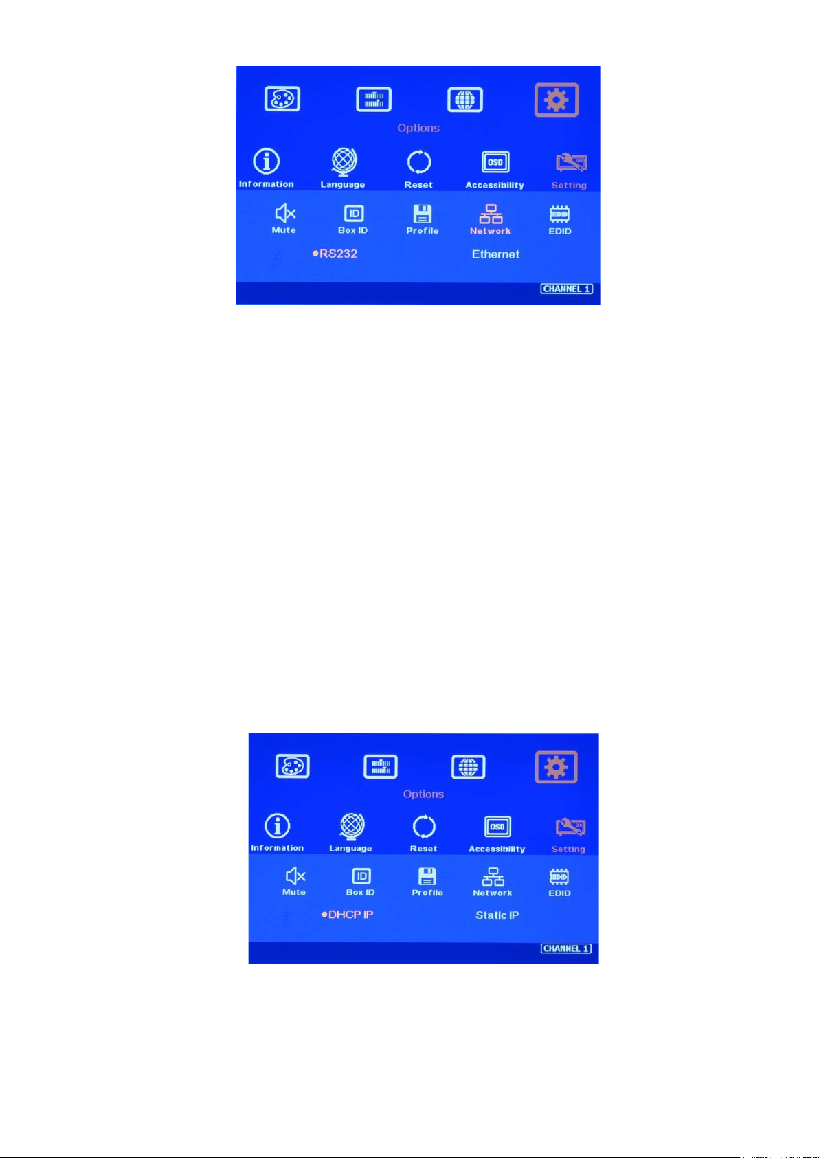
7 Step 7– System Settings: Box ID、RS232、Ethernet
Menu
hotkey
Box ID, RS232 and Ethernet settings shall be executed through CH-1 or CH-2. Please connect CH-
1 or CH-2 with monitor if user wants to see the system settings through OSD.
User can control or operate G406 settings through Ethernet. Default IP address is 192.168.0.100.
User can set different IP address in each G406 through Ethernet, USB or remote controller so that
each G406 can be controlled independently.
7.1 Box ID
The range of Box ID is 0 ~ 99 for RS2323 command.
If user uses remote controller to do system operation, the Box ID range is 0 ~ 9.
7.2 IR remote controller
When all G406 or IR extenders are installed together in the control range from single remote
controller, user can do individual G406 control through below method.
Press[851],all the box OSD will be locked except ID #1 G406. The LED light will be flashing
in the locked unit and only ID #1 G406 can be operated.
Press[853],all the box OSD will be locked except ID #3 G406. The LED light will be flashing
in the locked unit and only ID #3 G406 can be operated.
Press[850],all the box OSD will be unlocked and can be operated through remote
7.3 RS232 settings
controller.
9
G406 User Guide Document: G406-3
------------------------------------------------------------------------------------------------------------------------------------------------
RS232 is designed with DB-9 connector. User can select baud rate between 11520 and 9600.
We can provide UART protocol for the control from RS-232, USB, or Ethernet.
7.4 Ethernet
User needs to connect G406 to WiFi Router or switch/hub through RJ45 to LAN port. Then User
can control the system through Ethernet.
Open web browser (Google Chrome or Internet Explorer) and input IP address, user can see
GeoBox WebGui and see virtual keys and menu similar to OSD for further system operation. There
is no additional software tool is required.
UHDWall Manager PC Tool (UWM) is another web tool that has full function for system settings
and operation. It can also update Firmware or MCU code. UWM can be downloaded from VNS
website.
Each G406 can set different IP address for independent operation and control.
Please use < > OSD keys to select OSD menu items and use ˄ ˅ OSD keys to change IP address.
If G406 is connected with WiFi Router (through LAN port), user can control G406 through WiFi via
PC, iPad or mobile phone.
8 Step 8 – Conventional Video Wall Settings
Press [Video Wall] hotkey on Front Panel or Remote Controller to activate [Video Wall] menu. WebGui and
UWM PC tool are available for setup through Ethernet.
Note: Image flip and rotation are only available when input resolution is under 4k/2k @30Hz
10

G406 User Guide Document: G406-3
------------------------------------------------------------------------------------------------------------------------------------------------
.
8.1 [Zoom]
Use [Zoom] to split the display in horizontal and vertical directions. GeoBox will cut the image into
different sections. Maximum split image is 15 in both horizontal and vertical directions.
For 3x1 video wall display
Horizontal Zoom= 3, Vertical Zoom = 1
For 3x3 video wall display
Horizontal Zoom = 3, Vertical Zoom =3
8.2 [Pan]
[Pan] will assign the location of each split image in the video wall in both horizontal and vertical
directions. Horizontal direction is counted from Left to Right and Vertical direction is counted from Top to
Bottom.
In the case of 3x3 video wall display, Pan settings are as below:
11

G406 User Guide Document: G406-3
------------------------------------------------------------------------------------------------------------------------------------------------
8.3 [Overlap] – Position Alignment
[Overlap] adjustment changes the cropping area of the source image so that image position in each
monitor will be shifted. It can compensate Bezel Size of the monitor and correct misalignment in monitor
installation. If overlap value is decreased, each monitor will crop less image area and cause [zoom in]
(enlarged) effect. If overlap value is increased, each monitor will crop more image area and cause [zoom
out] (shrunk) effect. User can also use this function to correct position mis-alignment in installation, shift
image location for irregular video wall and set overlap area for projector edge blending application.
For No. monitor: For No.
Horizontal Pan = 3 Horizontal Pan = 3
Vertical Pan = 1 Vertical Pan = 2
monitor:
Maximum [Overlap] adjustment value is 900 pixels in all directions.
User can see the image and select Edge to adjust [Overlap] value for Bezel compensation and to
adjust image mis-alignment due to monitor installation issue.
User can use [Overlap] function to stretch the image outside video wall (some image will be
missing) or draw image inside video wall with Black blanking area at the edge. This function can
adjust the aspect ratio of the content to meet required aspect ratio of the video wall. Please see
more details in [Flexible Aspect Ratio Adjustment] section.
Asymmetric video wall can be achieved through overlap adjustment even with different size of
monitor and bezel dimension.
8.4 Bezel Compensation
Through [Overlap] menu, user can adjust image cropping area and adjust image position.
User can apply test pattern and reduce [Overlap] value to enlarge the image to the bezel center
line between two monitors to achieve bezel compensation.
User can also calculate the pixels number for bezel compensation based on the video wall
dimension and bezel size. If the video wall active display area is 360cm in width and the input
source is 3840, then the pixel number for each centimeter is 3840/360=10.67 pixel/cm. If the bezel
size is 12mm in one edge, then user can decrease Overlap value 10.67*1.2=12.8 (13) pixels to do
bezel compensation for that edge (to enlarge the image 13 pixels at that edge).
9 Irregular / Asymmetric Video Wall Settings
12

G406 User Guide Document: G406-3
------------------------------------------------------------------------------------------------------------------------------------------------
9.1 Introduction
Asymmetric video wall can be created by rotating monitor installation direction or position. User can
crop different area image for each monitor, rotate image direction and adjust image position
through G406 to achieve it.
Note: Image flip and rotation are only available when input resolution is under 4k/2k @30Hz.
User can use monitors with different dimensions, bezel size and resolution as display devices. No
data base for monitor is required and it allows user to have some deviation in installation position.
All of these factors can be corrected by GeoBox video wall settings.
G406 can only rotate the image at 90/180/270 degrees. The monitors need to be installed at
landscape or portrait position. If users want to install monitor at other rotation angle, G-403 model
should be used.
9.2 Wind-Mill Asymmetric Video Wall Setup Procedures
System connection (example)
Apply test pattern from signal source
Monitor can be with different bezel size,
screen dimensions, and resolution.
All monitors can be installed at 90 / 180 /
270 degree display direction.
Each monitor can be connected with any
output port. (In this example, CH1 TV1,
CH2 TV2, CH3 TV3, CH4 TV4)
User can select any signal source (i.e.
PS4 or PC) to display on video wall.
Able to display both signals from PS4 &
PC at the same time.
Below setup example is based on the
drawing as showed left.
Below test pattern should be applied as signal source for easy setup. Please download from below
website: http://www.vnstw.com/otherfile/14/file249-1-20180319194450-84.png
13

G406 User Guide Document: G406-3
TV1
TV4
TV3
TV2
------------------------------------------------------------------------------------------------------------------------------------------------
Test pattern applied
to video wall
Test pattern downloaded from
VNS website
Split the content by [Zoom]
- Set [Horizontal Zoom]=2, [Vertical Zoom]=2 in all channels.
- If TV2 & TV3 horizontal dimension is small, user can set TV2 & TV3 [Horizontal Zoom] = 4 and
[Horizontal Pan]: TV2=3, TV3=2, so that user can reduce the image position adjustment range.
Assign image location by [Pan]
- Set [Horizontal Pan]: TV1=1, TV2=2, TV3=1, TV4=2
- Set [Vertical Pan]: TV1=1, TV2=1, TV3=2, TV4=2
Image rotation
Use [Orientation] menu to
rotate images in TV2 and TV3
to display the same image
direction.
14

G406 User Guide Document: G406-3
rotation.
TV2
TV3
------------------------------------------------------------------------------------------------------------------------------------------------
Before TV2 & TV3
image 90 degrees
TV1
TV4
After TV2 & TV3
image 90 degrees
rotation.
TV1
TV3
Video wall
center line
TV2
TV4
Max. video wall
display borders
Set standard position as reference in horizontal and vertical directions
- User should determine Horizontal & Vertical image sizes and reference position so that all
monitors have criteria for image position adjustment.
- Usually, image display borders are the maximum active display borders in the video wall.
- In the above example, the horizontal borders are decided by TV1 & TV4. Vertical borders are
decided by TV2 & TV3.
- User can decide video wall display center through test pattern. It can be asymmetric.
Adjust image position by [Overlap] menu to finalize video wall settings
1 [Overlap] is to change image capture
range.
2 Decrease value in Top Edge of TV1
will stretch top edge of TV1 to match
image position of TV2.
3 For TV2 adjustment, user needs to
adjust Overlap value based on the
actual image direction but not based
on OSD direction. In this example,
user needs to stretch Right Edge to
match TV4.
15

G406 User Guide Document: G406-3
------------------------------------------------------------------------------------------------------------------------------------------------
After decrease TV1
[Overlap] value at Top
Edge
After decrease TV3
[Overlap] value at Left
Edge
After decrease TV2
[Overlap] value at Right
Edge
After decrease TV4
[Overlap] value at Bottom
Edge, then it is finished.
9.3 Square Asymmetric Video Wall Setup Procedures
Step 1: Video Wall settings for all channels
[Zoom]: H=2, V=2
[Pan]: TV1: H=1, V=1, TV2: H=2, V=1, TV3: H=1, V=2, TV4: H=2, V=2
Step 2: Apply Test Pattern and Rotate TV1 & TV4 images at 90 degrees
Original Image after applied test pattern Image after image rotation in TV1 & TV4
16

G406 User Guide Document: G406-3
TV1
TV2
TV3
TV
4
TV2
TV1
TV3
TV4
------------------------------------------------------------------------------------------------------------------------------------------------
Step 3: Determined image center, marked with paper tape.
Step 4: Set standard Position Reference in horizontal and vertical directions
Horizontal Position Reference is
determined by TV2 & TV3 and Vertical
Position Reference is determined by TV1
& TV4.
Once user can line up the image center
to Video wall center H&V lines, it can
serve as Position Reference lines.
Left figure shows the result after setting
Horizontal and Vertical Position
Reference (Move TV1 center line up,
TV2 center line to Right, TV3 center line
to Left and TV4 center line to down—
please see the arrow direction)
TV1: increase [Overlap] value in Bottom Edge to move Horizontal center line up to video wall
center
TV2: increase [Overlap] value in Left Edge to move Vertical center line right to video wall center.
TV3: increase [Overlap] value in Right Edge to move Vertical center line left to video wall center.
TV4: increase [Overlap] value in Top Edge to move Horizontal center line down to video wall
center.
Step 5: Individual monitor position adjustment based on Horizontal and Vertical Position Reference
resulting from the previous step 4.
17

G406 User Guide Document: G406-3
------------------------------------------------------------------------------------------------------------------------------------------------
TV1: increase [Overlap] value in Left Edge and decrease [Overlap] value in Right Edge to align
Vertical lines to match TV3
TV2: increase [Overlap] value in Top Edge and decrease [Overlap] value in Bottom Edge to align
Horizontal lines to match TV1
TV3: increase [Overlap] value in Bottom Edge and decrease [Overlap] value in Top Edge to align
Horizontal lines to match TV4
TV4: increase [Overlap] value in Right Edge and decrease [Overlap] value in Left Edge to align
Vertical lines to match TV2
Step 6: After final image position, all horizontal and vertical pattern can be matched together. The
setup procedure is finished.
1st alignment to set
Position Reference
(Set center lines)
2nd alignment to
finish all position
alignments
Aspect Ratio and image distortion
- If the source content aspect ratio is not 1:1 in this Video Wall setting, the final image will have
some distortion.
- User can adjust source resolution and content aspect ratio to fix this issue
Set display EDID with 2160*2160 with same ratio as the aspect ratio of Video Wall.
Use PC as signal source with 2160*2160 output resolution and use content with 1:1
aspect ratio. Customized output resolution setting in PC may be required.
- If source resolution and content don’t match the above conditions, user can adjust the display
aspect ratio in video wall settings to reduce image distortion but it may have below issues:
With some blanking area at some borders.
Display with full screen but some image will be stretched outside display borders and
can’t be seen.
- If user wants to change video wall display image aspect ratio, user needs to adjust Position
Reference Line first. In this example, if user wants to stretch horizontal image, user needs to
18

G406 User Guide Document: G406-3
------------------------------------------------------------------------------------------------------------------------------------------------
adjust TV3 and TV2 horizontal scaling factor first (grid size), then to align TV1 and TV4 to
match TV3 and TV2 with test pattern.
9.4 Other Big Scale Asymmetric Video Wall
If there is a video wall required large number of controllers to achieve it, users can have two options:
A. To adjust image directly through remote control and test pattern
a. To apply test pattern and familiar with test pattern and related positions.
b. To execute [Zoom], [Pan] and image rotation settings.
c. After individual LCD image location is determined, you can use remote control directly to
adjust the image location according to the test pattern.
d. The general adjustment order is from the video wall center and outer edges first. If you can
adjust the size of the grid in horizontal and vertical directions in some monitors as reference
baselines, then all other monitors can be adjusted according to these baselines.
B. The second way is to do position measurement for each monitor according to design drawing or
picture, and use remote control and test patterns to input adjusting parameters directly.
a. First step is to measure H&V active display area dimensions of the complete video wall setup,
for example, 400cm X 180cm.
b. Determine the signal source resolution: For example, 3840*2160
c. Calculate the desired display pixel per each centimeter: horizontal: 3840/400=9.6 pixel/cm,
vertical: 2160/180= 12 pixels/cm
d. Based on the monitor layout, to execute [Zoom], [Pan] and rotate the image if necessary.
e. When the image position of individual LCD is determined, user needs to measure the
distance between corner position of active display area in each monitor and the image
location determined by the [Zoom] and [Pan].
f. Using these distances and pixel densities per centimeter, you can calculate the approximate
horizontal and vertical position adjustment pixels.
g. Use the remote control to adjust the image position directly according to the calculated value
and the test pattern.
Example of an irregular TV wall setting with 8 monitors
a. The actual physical pixel on the upper edge display is: 6000. If the 3840*2160 signal
source is used, the signal source pixel on the upper edge is 3840. So the actual ratio is
6000/3840=1.5625. The vertical actual ratio of the 3000/2160=1.3889
b. When user executes Video Wall [Overlap] setting, it adjusts cropping area of the signal
source and changes the image position accordingly.
19

G406 User Guide Document: G406-3
------------------------------------------------------------------------------------------------------------------------------------------------
TV1 settings:
a. [Zoom]: H=6, V=2, [Pan]: H=1, V=1, [Image orientation]: 90 degrees or 270 degrees.
b. When TV1 horizontal zoom is 6, the actual hardware pixel in each horizontal section is
6000/6=1000. TV1 's vertical zoom is v=2, the actual hardware pixel in each vertical section is
3000/2=1500
c. The horizontal edge of TV1 should be assigned with 1080 pixels, but [Zoom] setting only assigns
1000 pixels to TV1. It is necessary to use the [overlap] adjustment function to add 80 pixels to the
TV1. After converting to the signal source pixel, the TV1 [Overlap][Right Edge] adjustment
value should be: 80/1.5625=51.2 Pixel (+51).
d. The vertical edge should be assigned with 1920 pixels, but [Zoom] setting assigns 3000/2=1500
pixels to TV1. It is necessary to use [overlap] adjustment function to add 1920-1500=420 pixel to
TV1. After converting to signal source pixel, TV2 [Overlap][Bottom Edge] overlap adjustment
value is: 420/ 1.3889=302.4 Pixel (+302).
TV2 settings:
a. [Zoom]: H=4, V=2, [Pan]: H=2, V=1
b. When the TV2 horizontal zoom is 4, the actual hardware pixel in each horizontal section is
6000/4=1500. TV2 's vertical zoom is V=2, the actual hardware pixel in each vertical section is
3000/2=1500
c. The horizontal edge of TV2 should be assigned with 1920 pixels, but [Zoom] setting only assigns
1500 pixels to TV2. It is necessary to use the [overlap] adjustment function to add 420 pixels to
the TV2. After converting to the signal source pixel, the TV2 [Overlap][Right Edge] adjustment
value should be: 420/1.5625=268.2 Pixel (+268).
d. The vertical edge should be assigned with 1080 pixels, but [Zoom] setting only assigns
3000/2=1500 pixels to TV2. It is necessary to use [overlap] adjustment function to decrease
1500-1080=420 pixel to TV2. After converting to signal source pixel, TV2 [Overlap][Bottom
Edge] overlap adjustment value is: 420/ 1.3889=302.4 Pixel (-302).
TV3-TV8 settings:
20

G406 User Guide Document: G406-3
------------------------------------------------------------------------------------------------------------------------------------------------
a. Below is [Overlap] adjusting value for each monitor without taking bezel compensation into
account.
b. If bezel compensation is required, user needs to enlarge the image in each monitor to the center
line between two monitors (some image will disappear). Assume the bezel size is 10mm and the
monitor is 42”(active display area is 930*523mm)。
Horizontal pixel density: 3840/ (930*2+523*2+10*6)= 1.295 /mm
The pixel inside bezel is 1.295*1=13 pixels
c. [Overlap] value after considering bezel compensation:
21

G406 User Guide Document: G406-3
TV1 TV2 TV3
------------------------------------------------------------------------------------------------------------------------------------------------
Two G406 can build
TV wall as Left.
More irregular video wall example:
Method 1: Calculate [Overlap] adjustment pixels based on design drawing or installation
picture.
a. Users can draw an outer frame in the display area using a photo or project drawing.
b. Measure the vertical and horizontal dimensions of the outer frame, and divide the resolution of
the signal source by the horizontal and vertical outer frame dimensions to get the H&V pixel
density per centimeter.
c. Measure the distance of the display area in each monitor in both horizontal and vertical positions.
d. By using the position distance and pixel density, user can calculate the pixels for position
adjustment.
e. When user set [Zoom] and [Pan] for each monitor, user can also understand the TV wall cutting
position.
f. Based on the above information, user can calculate [Overlap] adjustment value. After finishing
[Overlap] adjustment, user can apply test pattern and execute position fine-tune.
Method 2: Apply test pattern and execute image position adjustment directly
a. Users can also align the image directly using the test pattern.
b. The image center point is estimated and marked.
c. Take the middle monitor TV1 as an example:
The center point of the TV wall is in the upper position of TV1.
Rotate the image, set [Zoom] as H=5 (about 1/5 in the horizontal direction), V=2
(approximately 1/2 in the vertical position), [Pan]: H=3 (in the 3rd position while H= 5), V=2
(vertical 2nd position).
Apply test pattern, select the TV1 connection channel.
22

G406 User Guide Document: G406-3
------------------------------------------------------------------------------------------------------------------------------------------------
Use [Overlap] menu to select the top/bottom edge to adjust the vertical position of the test
pattern and let the center point of test patter to match TV wall center point.
Then adjust the left and right edge [Overlap] value so that the horizontal grid and the vertical
grid have similar size.
Next step is to set TV2/TV3 [Zoom] and [Pan]: set [Zoom]: H=3 (about 1/3 of the horizontal
direction), V=4 (approximately 1/4 of the vertical position). TV2 [Pan]: H=1 (1st position of
horizontal direction), V=3 (3rd position of vertical direction); TV3 [Pan]: H=3 (the 3rd position of
horizontal direction), V=3 (3rd position of vertical direction), and uses [Overlap] function to let
the test pattern align together. If there are some images missing or black borders at both
sides, user can shrink/enlarge the TV1/TV2/TV3 grid size, so that the grid can cover full frame
of TV wall with the similar horizontal grid size in all TV.
The other three upper monitors can be set in a similar manner so that the test pattern can be
aligned together and the grid size can be consistent with the other three monitors in both
vertical and horizontal directions.
If necessary, image fine-tune is required to complete the whole setup.
10 Flexible Aspect Ratio Adjustment
User can change the aspect ratio of the image with black borders or to stretch the image in specific direction
to compensate the aspect ratio difference between video wall and the content. The Maximum adjustment
range is 900 pixels in each edge.
23

G406 User Guide Document: G406-3
pixels in each edge.
------------------------------------------------------------------------------------------------------------------------------------------------
Activate [Overlap] under [Video Wall] menu
1. User can select the channel and the
edge required for edge shift, then adjust
Overlap value to see aspect ratio
change.
2. The image position shift range is +_900
1. If the image is at portrait position, this function is only available under input signal up to 4k/2k @30Hz.
2. If Video Wall [Zoom] is set to H=2 & V=2 or above, user can apply 4k/2k @60Hz input signal. The
adjustment range (900 pixels) is calculated based on signal source resolution.
3. When user adjusts Overlap value in one monitor, it will also change the scaling factor. User needs to
adjust the Overlap value in other monitors to let all monitors has the same scaling factor.
4. The adjustment range of 900 pixels is calculated according to the signal source resolution. If the signal
source is 4k/2k and the adjustment value is 900 pixels, when switching to 1080p input signal, the
adjustment value will be converted to 450 pixels automatically to maintain the same image position. If the
input signal source is 1080p and the adjustment value is 900 pixels, when switching to the 4k/2k input
signal, the adjustment value will be maintained at 900 pixels, and the image position changes to the
position of 900 pixels (about half the distance) of the 4k/2k signal.
11 Save System Settings through OSD Menu
After finishing system settings, user can save the setting by OSD menu through [Menu]
[Options] [Setting] [Profile] [Save] [Index 1-5]. [Save] Profile will take effect for two
channels in the same display group. User needs to Save CH1/CH2 & CH3/CH4 separately for one
G-406.
User can recall the setting (Load) through IR remote controller or [Profile] hotkey on Front Panel.
Five different display settings can be saved to [Profile]. The data stored in Profile include EDID
setting, input source, output resolution, color settings and all user customized settings.
24

G406 User Guide Document: G406-3
------------------------------------------------------------------------------------------------------------------------------------------------
When user power off the system, G406 will save user setting without loss even the setting is not
saved into Profile Index, unless someone to change the setting.
When system has been reset from OSD menu or update new Firmware, Profile data will still be
kept inside G406.
12 Save or backup settings through PC Tool
12.1 UWM PC tool is available for system setup via PC through USB or Ethernet.
12.2 User can save or backup the settings into PC and recall or copy to another unit at any time.
13 Load Profile Index through Front Panel hotkeys
Load Profile Index
Push [Profile key] Select Index # on Front Panel. No [Enter] is required.
Index # keys on front panel
HDMI-1: Index 1, HDMI-2: Index 2, DP 1/2: Index 3, Info: Index 4, Align: Index 5
No Profile [Save] shortcut key is available to avoid erasing original settings by mistake.
Profile Load will apply to all channels at the same time.
Profile Index #1 #2 #3 #4 #5
Key for Profile
Load (Recall)
14 Load/Save Profile Index through Remote controller
Press [Profile] shortcut key Select number keys 1-5 to recall Index 1 – Index 5.
Profile Load will apply to all channels at the same time.
[Save] hotkey at the bottom of remote controller is available for user to save the settings.
15 Helpful tips for video wall settings
15.1 Image distortion and aspect ratio issues
If the content aspect ratio is different from video wall, it will cause image distortion. User can adjust
aspect ratio through [Overlap] settings. However, you will have two choices:
Full screen display but some content will be drawn to outside border and missing.
Draw the image into video wall and keep some blanking border at some edge.
15.2 If the signal is from PC, user can set customized EDID in GeoBox to let PC output expected output
resolution. Some PC may not follow GeoBox EDID resolution setting and require customized output
setting from display card.
25

G406 User Guide Document: G406-3
------------------------------------------------------------------------------------------------------------------------------------------------
15.3 User can set different video wall settings in each channel and crop different area for the display. In
combination with ZOOM, PAN and OVERLAP settings, user can crop any location of the image for each
LCD, no matter it is in landscape or portrait position.
15.4 Pay attention to image rotation limitations in input signal resolution. G406 doesn’t have image rotation
function when the input is 4k/60 Hz.
15.5 G406 can support interlaced signal source (i.e. 1080i). However, if user rotates or flips the image, there
will be no 3D motion adaptive de-interlaced function. User may see some small flick image while the
input is still image. We strongly recommend applying progressive signal for the best video quality.
15.6 Some media players will output maximum resolution when it is powered on each time but not follow the
EDID settings in sink device. It will cause abnormal display in the video wall if this video wall has image
rotation setting and the signal source resolution is more than 4k/60Hz because G406 can only support
image rotation under 4k/30Hz source signal.
16 Convenient Setting In Multiple Unit Application
16.1 Setup by Remote Controller
16.1.1 If multiple units are used, user can set different [Box ID] (#1 - #99) or IP address in each Box for
individual control. For IR control, the [Box ID] number range is #1 - #9.
16.1.2 User can control individual GeoBox through below method when all boxes or IR extender
receivers are installed together.
Press 851 number key on remote controller will lock all other G406 OSD menu except G406
with Box ID #1. User can see flashing LED on the Front Panel for the units with OSD locked.
Press 853 will only unlock ID # 3 G406 for further OSD operation and lock all the others.
Press 850 will unlock all G406 OSD Menu. Remote controller can control all boxes at the same
time.
16.2 Setup by Ethernet
User can connect all G406 in one Ethernet Router (WiFi Router or switch/hub) through LAN ports and
set different Static IP address for each Box, then use WebGui virtual keys or UWM PC tool to control
each G406 independently. Default IP address is 192.168.0.100. Web Server function is available.
Please contact us for more details.
16.2.1 WebGui
WebGui is embedded inside G406. Once user connects G406 with PC through Ethernet, user
can access WebGui and execute all operation similar to OSD menu through Virtual Keys and
OSD Menu. No PC or appropriate software tool is required.
The connection can go through Ethernet router LAN port, WiFi Router or Crossover Cab 5/6
cable. User can set each G406 with different static IP address in the same domain, then open
Google Chrome or Microsoft Explorer browser with IP address to access each unit of G406 for
independent operation. There is no limitation in the number of G406 that can be controller at the
same time.
User can turn on/off the system through WebGui and see the status through power indicator.
26

G406 User Guide Document: G406-3
Channel selection
Power Indicator
Input
selection
OSD
Example: WebGui for Video Wall
setting
------------------------------------------------------------------------------------------------------------------------------------------------
16.2.2 UHDWall Manager (UWM) PC Tool
UWM is a PC tool executed through PC. User needs to download this tool from VNS website.
Once user connects G406 with PC through Ethernet and open UWM, user can access UWM
and execute all operation similar to OSD menu through PC keyboard and mouse. User can also
backup system setting in PC and restore/copy to other units.
27

G406 User Guide Document: G406-3
------------------------------------------------------------------------------------------------------------------------------------------------
User can execute full operation functions and also update Firmware and MCU code through
UWM. User can control multiple units at the same time through switching IP address.
The color icons on the top of CH indicator is to show the system connection status. Green means
the channel has detected display device and Yellow means input signal is connected. In the above
example, channel 4 output is not connected with monitor.
17 System Structure and Control
RS232 and Ethernet are available for system control. They can be used simultaneously to provide the most
flexibility in system control.
17.1 System Structure: Group A & Group B
G406 can be treated as one quad channel processor or two dual channel processors. Channel 1/2
is called Group A and channel 3/4 is called Group B.
HDMI-1 & HDMI-2 input signals can be connected to Group A & B.
DP1 is sole for Group A and DP2 is sole for Group B.
17.2 OSD Command Execution in Group A & Group B
The following command will be applied to all channels in Group A & Group B at the same time.
- [Profile] [Load] [Index]
- [Options] [Setting] [Box ID]: one G406 has one Box ID and can only be set by CH1 or CH2.
- [Options] [Setting][Mute]
- [Options] [Setting][Network]: one G406 has one Network setting and can only be set by
CH1 or CH2.
The following commands will be applied to Group A and Group B separately. The commands will
apply to two channels inside the same display Group.
- [Image Properties] [Scaling]: select full screen or original aspect ratio
28

G406 User Guide Document: G406-3
------------------------------------------------------------------------------------------------------------------------------------------------
- [Image Properties] [Output Mode]: select output resolution
- [Options] [Information]: show system information
- [Options] [Language]: select OSD language
- [Options] [Reset]
- [Options] [Accessibility][OSD Time Out]
- [Options] [Accessibility][Logo Time Out]
- [Options] [Accessibility][Standby Time]
- [Options] [Accessibility][Black Screen]
- [Options] [Setting][Mute]
- [Options] [Setting][Profile][Save]
- [Options] [Setting][Profile][Load]: If through below OSD operation ( [Menu] [Setting]
[Profile] [Load] ), the result will apply to CH1/2 or CH3/4 but not all channels. If via [Profile]
hotkey on front panel or remote controller to Load Index, the result will apply to all channels at
the same time.
The following commands will be applied to each channel independently.
- Color adjustment: All menu under [Picture]
- [Image Properties] [ Color]
- [Image Properties] [Input Signal]
DP-1 is for CH1/CH2 and DP-2 is for CH3/CH4. Each display Group can’t select HDMI-1 &
HDMI-2 at the same time. Please see Section 2 for more details.
- [Image Properties] [Orientation]
17.3 EDID Setting
- [Options] [Setting][EDID]. [Customize] EDID is in the selection list. The range is H=
1024~3860, V= 720~2400.
- HDMI-1 & HDMI-2: select CH1 or CH2 with HDMI input, then to set EDID
- DP1 & DP2: select CH1 or CH2 with DP1 input to set DP1 EDID. Select CH3 or CH4 with DP2
input to set EDID.
- User can set EDID directly through WebGui and UWM by selecting input port.
17.4 HDMI vs. DVI Output Signal
HDMI digital signal is compatible with DVI signal. Most of display devices can support both digital
signals. However, some old equipment may have less flexibility in digital input signal compatibility. In this
case, user may need to select DVI output format for normal display.
29

G406 User Guide Document: G406-3
------------------------------------------------------------------------------------------------------------------------------------------------
17.5 System Standby and Automatically Turn Off Output Signal
- [Options] [Accessibility][Standby Time]
- If set [Standby Time] at 60, the system will get into Standby Mode after 60 seconds when no
input signal is detected. The output signals from G406 will also be terminated at the same time.
If G406 detects input signal again, it will automatically turn on the system again.
- If the monitor can automatically turn off/on by detecting input signal, user can control signal
source to execute entire system on/off control.
17.6 RS232 Setting
RS232 interface is designed with DB-9 connector. User can select 11520 or 9600 baud rate.
The protocol can be implemented via RS-232, USB, Ethernet or other forthcoming communication
methods. Please contact us if user requires RS232 protocol.
Please set RS232 baud rate through CH1 or CH2.
17.7 Ethernet Setting
Ethernet control: G406 is integrated with RJ45 connector. Please connect G406 with Ethernet
Router via LAN port.
User can controller G406 through Ethernet or WiFi through PC or mobile devices. A WebGui with
virtual keypads icons will be showed in control devices for user to execute OSD function of G406.
UWM PC tool is available for full function operation and firmware & MCU code update.
DHCP & Static IP can be set in each G406 for independent operation.
User can use < > OSD direction keys to access to the item for the modification and ˄ ˅ OSD
direction keys to change the IP address settings.
If WiFi router is connected, G406 can be controlled through WiFi by PC, mobile phone or iPad.
30

G406 User Guide Document: G406-3
------------------------------------------------------------------------------------------------------------------------------------------------
17.8 Change Background Color
When no signal input, the system will show blue color background with [Power Saving Mode] message on
the screen. User can change background color to black from the OSD menu as below.
17.9 Change OSD Menu display time
User can set [Options] [Accessibility] [Menu time out][0] to display OSD menu all the time.
17.10 Change Splash screen logo display time
User can set [Options] [Accessibility] [Logo time out][0] to eliminate splash screen Logo.
18 Limitations in Image Flip and Rotation
Image 90/270 degrees image rotation is only available in input resolution under 4k/2k @30Hz (included).
While image is rotated or flipped, there will be no 3D motion adaptive de-interlaced function. We recommend
apply progressive source signal to get the best video quality.
19 Limitation in Audio Output
User can only select one audio output from each display group - Group A (CH1/CH2) and Group B
(CH3/CH4). In each Group, if both HDMI and DP input are selected, then only HDMI audio will be selected as
audio output.
20 Trouble Shooting
20.1 Front Panel LED lights
User should see Input/Output LED lights in each channel. If no light illuminated in specific channel,
please check Input/Output connecting cables, signal source & monitor in that channel.
If user sees continuous flashing in some channel LED, it means OSD may be locked. Please press
[Menu] key for 5 seconds, it will disable [OSD locked] function.
If [INFO] key LED is lighted, the OSD Menu is locked and can’t be used. Please use remote
controller and press [850] number keys to disable OSD Menu Lock.
20.2 Intermittent or Loss of Input Signal
Check the HDMI cable quality and make sure all cables are fitted correctly. 4k/60 signal requires
high speed certified cables.
31

G406 User Guide Document: G406-3
------------------------------------------------------------------------------------------------------------------------------------------------
Cable length: Connecting cable length should be short as possible. Replace a short cable to verify
the possible root cause.
HDCP compliant issues: If the input source or the monitors are not HDCP compliant, it is possible
to stop G406 from negotiating HDCP link and show intermittent, abnormal or no image.
Resolution issues: check if signal source and connecting cables can provide right signal requested
by G406.
DVI/HDMI signal compatibility: some display devices may only support HDMI or DVI video signal
and execute wrong signal format detecting. The default output is HDMI. User can change output
with DVI format through [Options] [Setting] [DVI] [On].
Usually, to swap with different cable, output channel, signal source and monitor can verify the root
cause for the failure.
When it is possible to have signal compatibility issue, user can add one HDMI splitter or switch in
the middle to change signal impedance. It may fix the issue.
20.3 Image rotation can’t be implemented
If the input signal is above 4k/2k @30Hz, image 90/270 degree rotation function will be disabled.
20.4 Video quality issues
Use the highest resolution and number of color bits (RGB 4:4:4) images allowed by G406 to be
used as a signal source whenever possible.
There are a number of lower-quality AV players, the specification and actual output are difference,
or because of the use of lower color sampling bits or poor image compression technology, resulting
in lower quality or image is not smooth (LAG).
If the use of H.264/H.265 compressed files, please select a player with hardware decoding to get
smooth video quality.
If the input signal is interlaced signal (interlaced-1080i), and the image is rotated or flipped, then
the channel will have no [3D Motion adaptive de-interlaced] processing function. If user applies
static image source, the output video will have a slight jitter phenomenon. The processing channel
quality will be reduced. Use a progressive signal source setting (1080p/2160p) whenever possible.
Please press [INFO] shortcut key to check the input/output signal settings.
20.5 System setting can’t be executed:
System control applied to complete system can only be executed through CH-1.
After FW update, please insert small pin into RESET hole on back panel for 5 seconds to reset the
system to default to eliminate unnecessary settings. It will not affect Profile Index storage data.
20.6 Synchronization issue in the outputs
The input refresh rate should be the same as output refresh rate so that the system can implement
Frame Lock to synchronize all the outputs. If the input source is 50Hz with 60Hz output, then it is
possible to see some lag among the displays.
The display devices may have different delay time under different settings. For examples, if the
system with high end video processing, such as noise reduction or ME/MC, it may increase few
frame delays. Please make sure all the display with the same settings.
21 Technical support
32

G406 User Guide Document: G406-3
------------------------------------------------------------------------------------------------------------------------------------------------
User can send e-mail to support@vnstw.com together with as much information as possible.
The following information is required for a swift response.
Sink device (monitor): type and model number
Monitor layout or specific application details (shape of video wall).
GeoBox model No. and series No.
Detailed timing of signal source and resolution.
Press [Info] key to get System Information and send the data to us, including input/output
timing and F/W version.
The exact nature of the problem. Please be as detailed as possible.
If possible, please attach the Pictures of the issue.
Usually we will response with 24 hours (excluding weekends)
Please note that if the machine is sent back for repair, user needs to pay for some delivery cost.
22 Safety Precaution and Maintenance
22.1 Power Supply
Please connect electric power for all devices in the system from the same Power Distribution Box with
correct grounding. Open the power after finishing system connection to reduce the risk for system
damage from high floating voltage.
22.2 Working Environment
Please locate G406 in an environment free from dust, moisture and high temperature with good
ventilation.
22.3 Warranty:
This device is designed and tested to the highest standards and backed by two years’ parts and labor
warranty. Warranties are effective upon the first delivery date to the end customer and are non-
transferable. Warranty period extension is available up to 5 years through paying extra charges.
22.4 Maintenance and Repair
Apart from what is detailed in User Guide, maintenance should be carried out by competent technician
assigned by VNS. If G406 is physically damaged, it should be returned for repair using VNS RMA
procedures. If the unit is opened by user, it will lose the right for warranty protection.
33

G406 User Guide Document: G406-3
------------------------------------------------------------------------------------------------------------------------------------------------
Specifications
16. Input: 2x HDMI 2.0b for all channels, 1x
DP1.2a for CH 1/2, 1x DP1.2a for CH 3/4
17. HDCP: HDMI: V2.2/V1.4, DP: V1.3
18. Max. input resolution: 4096x2400 60fps
19. Output: 4x HDMI up to 1080P & WUXGA
20. 2x HDMI 2.0 loop out ports for multiple unit
cascade & daisy chain connection
21. Support non-VESA STD input timings
22. Selectable output up to 1920x1200 60Hz
23. 10-bit processor, frame rate conversion
24. 4:4:4 Chroma sampling, 30 Color bits, 12-bit
RGB gamma CLUT
25. Support sRGB & xvYCC 8/10/12-bit deep
color processing.
26. Flexible aspect ratio adjustment in each edge
up to +_ 900 pixels.
27. 50Hz in/out to avoid video artifact.
1. Frame lock for synchronized outputs
2. Frame rate conversion.
3. High Dynamic Range (HDR) support: SMPTE ST-
2084, SMPTE ST-2086
4. Individual 90/180/270 rotation, flip, cropping,
scaling & color adjustment in each channel
5. 90/270 rotation only supports up to 4k/30Hz.
6. Matrix switch for multi-window display
7. Embedded HDMI/DP audio in each output
8. Selectable and programmable EDID
9. ESD Protection: ±8kV (Air-gap discharge), ±4kV
(Contact discharge)
10. DC 12V/1.1A, max. 13w, (100-240 VAC PSU)
11. Working environment: 45〫C, 10-90% RH
12. Control: Front panel keypads, IR, RS232, USB,
Ethernet
13. Dimensions: 440mm*194mm*45mm, Weight: 2.2kg
28. 3:2/2:2 cadence, low angle smooth algorithm,
high quality scaling engine
29. 3D motion adaptive de-interlace
14. CE/FCC/RoHS/Green Certified
15. 2 Year Warranty, paid extension is available
34

G406 User Guide Document: G406-3
------------------------------------------------------------------------------------------------------------------------------------------------
Revision History
Revision
Date Originator Comments
V1.0 2018-01-16 Steve Wang First version
V1.1 2018-01-17 Steve Wang Change front panel silk printing
V1.2 2018-01-18 Steve Wang Modify Load/Save Profile
V1.3 2018-02-17 Steve Wang Add irregular video wall setting and Ethernet
control
V1.4 2018-0315 Steve Wang Add New Overlap for aspect ratio adjustment
V1.5 2018-0510 Steve Wang Add large scale creative video wall settings
V1.6 2018-11-14 Steve Wang Add more contents
V1.7 2018-12-28 Steve Wang More information in system synchronization
35
 Loading...