


G-405 Quick User Manual Document: G-40501
------------------------------------------------------------------------------------------------------------------------------------------------
0
G-405 Quick user guide
Please see below instructions if you are new user for G-405
1. GeoBox installation:
a、 Unpacked and connect G-405 with 12V DC power supply unit and HDMI cables to any LCD. No specific
connection order is required.
b、 No limitation in the LCD size, resolution or aspect ratio, once the color is uniform enough with required
viewing angle.
c、 Please turn off Overscan function in TV set if you use TV as display device.
d、 If GeoBox is installed at a location that is not easy of access by remote controller, please extend IR
extender (with audio cable up to 20 meters) to a place for easy IR access.
2. Signal connection:
a、 Each G-405 consists of two processing modules with the capability to display dual contents in 4x LCD
(two LCDs in one processing module as one display unit). Please connect the same signal to both
processing modules through loop out port daisy chain connection by HDMI-A input port (Please see User
Manual Sect. 4.2).
b、 Signal source is required while installation. If no signal is applied, it will terminate output after 60 seconds.
User can go to [Options] [Accessibility] [Standby Time Out] to disable auto shut off function.
c、 If two video sources are required, user can display one or two contents on t he video wall based on
different input port selection & settings and save the setting in [Profile] that can be recalled at any time.
d、 Loop out port signal comes from HDMI-A input port. If second video source is required for video wall
display across 4 LCDs, 1x2 video distributor is required to provide the same signal to both processing
modules. The first signal source can be connected through loop out port without video distributor.
e、 If HDMI splitter is used, please select a splitter with [EDID] setting function so that it can pass correct
EDID information from GeoBox to signal source.
f、 During setup stage, if user applied 4k/2k image to G-405, the operation menu in signal source (PC) will
become very small. We propose to apply 1080p signal source for easy setup.
3. Familiar with OSD operation:
a、 Power on GeoBox, video source and LCD.
b、 After finishing boot up process, please press [Menu] key and [CH R/L] to switch between different
channels. OSD function will only apply to the channel that shows OSD.
c、 One Video Wall setting hotkey on the remote controller for user to quick access to Video Wall menu.
d、 Please be familiar with all the hotkeys in remote controller. It will save setup time.
e、 When two OSD appears on the screen at the same time, user can disable one OSD by press Menu key
on front panel. Then user can easily control only in one channel. Another way is to set Box ID described
as below in section 5.
4. GeoBox setup:
a、 To reset GeoBox via [Options] [Reset] [Reset all] to avoid any undesired settings inside Box.
b、 Press [INPUT] hotkey to select input port on both processing modules. User can see input port message
on the screen. Default is [HDMI A] input port.

G-405 Quick User Manual Document: G-40501
------------------------------------------------------------------------------------------------------------------------------------------------
1
c、 Press [OUTPUT] hotkey to select the output resolution. It will show the result on the screen. If this output
resolution is the same as display device, it will provide the best video quality.
d、 Please press [INFO] key in remote controller to confirm final input and output information.
e、 To set remote controller [OSD Time Out] hotkey to “0” to maintain OSD display while in setup stage.
5. Individual channel control:
a、 To set [Box ID] for each processing module through [Options] [Setting] [Box ID]. For example: to set
Upper module as #1 and Bottom module as #2 and the 2nd G-405 should be #3 and #4.
b、 Press [851] number key, the remote controller will lock all processing modules except Box ID #1. Only ID
#1 processing module can be accessed and controlled.
c、 Press [852] number key, then the remote controller will only control processing module with Box ID #2.
d、 Press [850] number key, it will unlock all processing modules and remote controller can control all units at
the same time. It is convenient while doing [Video Wall] setting.
e、 OSD can be locked while press [Menu] key for 5 seconds. Blinking LED on front panel means this module
is locked. Press [850] or Menu key for 5 seconds to unlocked it.
6. Start video wall setting:
a、 [Video Wall] Hotkey is available on front panel and also in IR remote controller.
b、 [Zoom]: split the image for LCD. Please see User Manual Sect. 4.4.
c、 [Pan]: assign image to each LCD.
d、 [Overlap]: to set bezel correction and image position. Please see User Manual Sect. 4.4.3..
e、 Irregular video wall position alignment, please see User Manual Sect. 5..
f、 For easy position and bezel alignment, please download Test pattern from website: www.vnstw.com.
7. Avoid Blanking border and adjust aspect ratio:
User can use [Overlap] setting to avoid blanking border or change image aspect ratio. Please see User Manual
Sect. 6.7.
8. EDID setting to optimized video quality:
a、 After finishing all settings, to activate [Option][Settings][EDID] menu and set optimized input signal
resolution (please see User Manual Sect. 8.4). It may be necessary to set PC or Media Player output
resolution manually in some case.
b、 EDID can be saved together with different display Profile to get the best result in all cases.
9. Power on/Off settings:
User can access to OSD menu [Options] [Accessibility] [Standby Time O ut] to set the time to terminate
output signal while no input signal is detected. If it is set to [60], it will automatically turn off output signal in 60
seconds while no input signal is detected. When it detects input signal, it will turn on again automatically.
10. Save final setting:
Please go to [Options] [Settings] [Profile] [Save] to save the settings. When power off the system, it will
maintain the setting without change. User can load the setting again from [Profile] hotkey on remote controller.
11. Load [Profile] into the system:
[Profile] hotkey is available on remote controller. User can press [Profile] key, then select the [Number] key to
load the Index saved by user.
G-405 Quick User Manual Document: G-40501
------------------------------------------------------------------------------------------------------------------------------------------------
2
G-405 User Manual
Pure hardware 4k/2k four channel Video Wall Processor
Support 4k/2k input in HDMI, DP & DVI input ports
Support video wall array up to 15x15
Image 180 degree flip function
Pixel base position alignment
4k/2k Loop out for daisy chain connection
Selectable EDID and can saved with display Profile
Technical support:
E-mail: support@vnstw.com
Tel: +886-2-2792-2819
Cell: +886-935-678-033
Skype: vns-inc
Version: 2.02
Website: www.vnstw.com.tw

G-405 Quick User Manual Document: G-40501
------------------------------------------------------------------------------------------------------------------------------------------------
3
Table of Contents
1 Introduction…………………………………………………………………………… 5
2 Specifications………………………………………………………………………… 6
3 Helpful tips…….……………………………………………………………….……... 7
4 Video Wall applications…………………………………………………………. …. 8
4.1 Features…………………………………………………………………………. 8
4.2 System connection for 4k/2k display………………………….…………… 9
4.3 Procedures for video wall setting..…………………………………………. 10
4.4 Start video wall settings……………………………………………………… 11
4.4.1 [Zoom] (To split the image for each TV)………………………….. … 11
4.4.2 [Pan] (To assign location for each TV)………………………………. 11
4.4.3 [Overlap] (Bezel compensation and location alignment)………… 12
4.5 Example for 2x2 video wall setting…………………………………………. 13
5 Advanced settings: Bezel compensation and Location alignment………….. 14
5.1 Bezel compensation…………………………………………………………… 14
5.2 Irregular TV wall position alignment……………………………….……….. 15
5.2.1 Procedures for position adjustment--[Overlap] setting……..….… 15
5.2.2 Aspect Ratio issue and blanking border in the image.……………. 16
5.2.3 More complicated irregular video wall position adjustment.……. 16
6 Application case study………………………………………………………………. 17
6.1 2x2 video wall with two different contents……………………………….... 17
6.2 Multiple contents in big video wall display………………………………... 17
6.3 2x2 video wall with two TV at flip down position………………………. … 18
6.4 4K/8Kvideo wall…………………………………………….…………………… 19
6.5 2x2 irregular video wall with PIP and rotation……………………………. 19
6.6 2x2 irregular video wall with two TV at portrait position……………….. 20
6.7 Aspect Ratio adjustment............................................................................ 20
6.8 Other application cases………………………………………………………. 21
6.8.1 Two TV at portrait position…………………………………………….. 21
6.8.2 Three TV at portrait position…………………………………………… 21
6.8.3 Four TV at portrait position with rotation angle…………………… 21
7 How to setup video wall with rotated angle.……………….……………………. 22
7.1 System connection……………………………………………………………. 22
7.2 Procedures for video wall alignment with rotated images.……………. 22
7.2.1 Apply test pattern……………………………………………………….. 22
7.2.2 Set video wall Zoom & Pan……………………………………………. 23
7.2.3 Rotated image for portrait TV……………….………………………… 23
7.2.4 Alignment via [Overlap] function……………………………………... 24
7.2.5 Aspect ratio adjustment……………………………………………….. 24
8 System control……………………………………………………………………….. 25

G-405 Quick User Manual Document: G-40501
------------------------------------------------------------------------------------------------------------------------------------------------
4
8.1 [Box ID].…………………………………………………………………………. 25
8.2 [Profile] setting………………………………………………………………….. 25
8.3 RS232 setting……………………………………………………………………. 26
8.3.1 Serial port setup……………………………………………………………. 26
8.3.2 Terminal setup………………………………………………………………. 26
8.3.3 Example of low cost RS232 controller………………………………….. 27
8.4 [EDID] setting…………………………………………………………………….. 27
9 Technical support…………………………………………………………………… 28
10 Revision Histroy.................................................................................................... 29
G-405 Quick User Manual Document: G-40501
------------------------------------------------------------------------------------------------------------------------------------------------
5
1 Introduction
G-405 is four channel high end 10-bit processor with 3D motion adaptive de-interlace, low angle smooth algorithm
and 3:2/2:2 film mode processing for 4k/2k video wall processing. It is integrated with video wall function for image
split, cropping, location assignment and pixel base high precise bezel management. Frame lock function can make
sure to have synchronized display in the complete video wall.
The structure of G-405 includes two independent processing modules to allow one content or two different video
source contents displayed in four TV video wall. Each processing module is designed with 4 input ports for flexible
connection with multiple signal sources and 4k/2k HDMI loop out port for daisy chain connection. The maximum
input resolution is up to 1080p @120Hz, 3840x2160 @30Hz or 3840x1080 @60Hz with 4:4:4 full sampling without
compression in all input ports, including HDMI, DisplayPort and DVI ports. Each output channel can execute 180〫
image flip separately to allow video wall with TV at flip down position to balance the bezel difference on the top and
bottom edges. User can set different display modes and recall in seconds to change the video wall display profiles. It
is a pure hardware system. No PC is required, easy to use and more reliable.
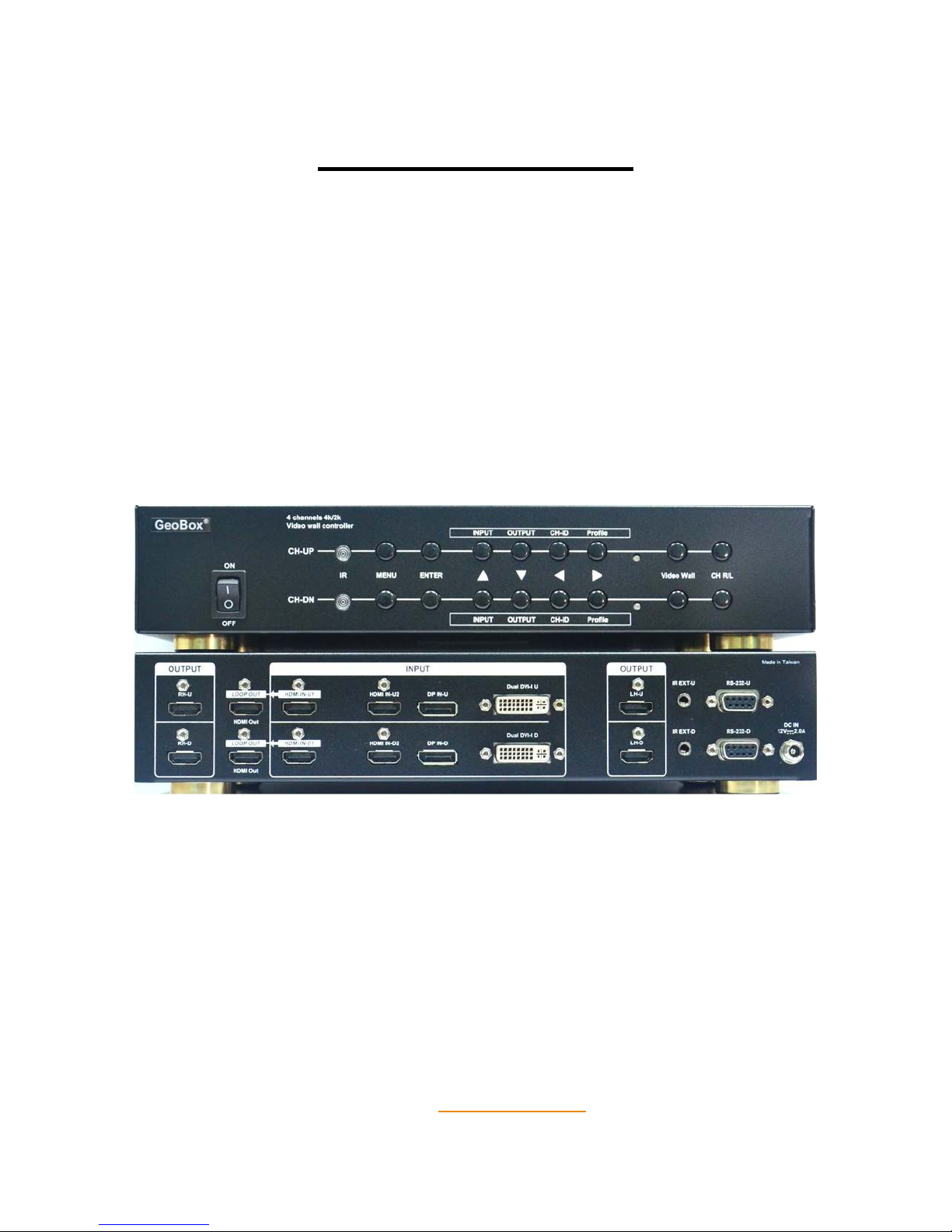
G-405 consists of two processing modules. Each module has its independent input/output, image flip and control
settings to allow flexible display for multiple contents & TV at different display directions.
Input: 2x HDMI, 1x DisplayPort, 1x DualLink DVI-I (support HDMI, DVI, VGA)
Output: 2x HDMI output ports with HDCP, one 4k/2k raw signal loop out port
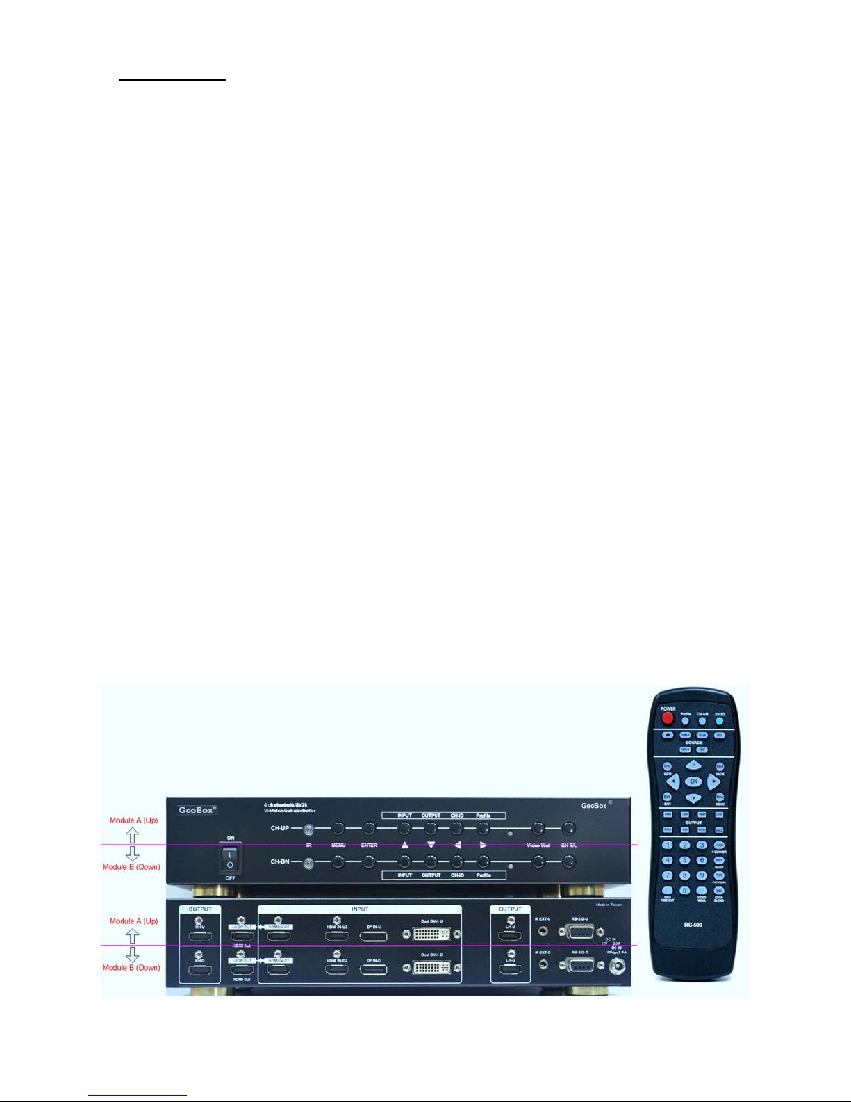
User can set different Box ID for module A and module B, then use remote controller to do independent control of
module A & B. If set module A Box ID as “1” and module B as “2”, then:
Press [851] will initiate remote control for module A. Then all the operations from remote control will only work for
module A and [852] will only work for module B. If [850], then remote control will control both module A & B.
G-405 Quick User Manual Document: G-40501
------------------------------------------------------------------------------------------------------------------------------------------------
6
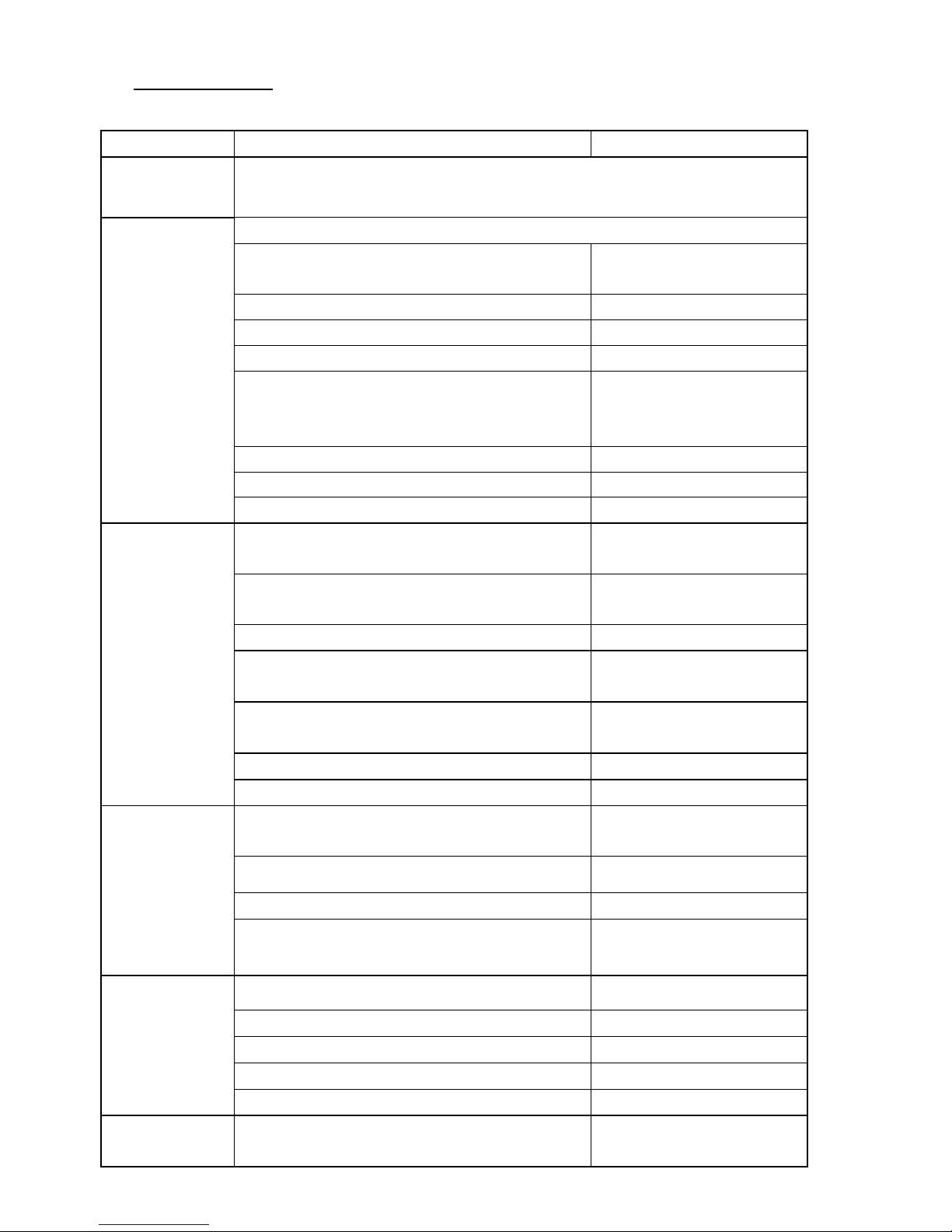
2 Specifications
Main items Features G-405
Main functions
Quad channel 4k/2k video wall controller with 180〫 image flip down function and +-
900 pixels image shift in H&V directions for irregular video wall display
Input & Output
Two video processing modules. Each module had below input/output ports.
Video Input Ports
2x HDMI, 1x DualLink DVI-I, 1x
DisplayPort
Video Output 2x HDMI for RH/LH output
Loop out port for daisy chain connection 1x 4k/2k HDMI loop out port
Support YPbPr video via DVI-I input port YPbPr adapter is required
Input resolution up to 1080p @120Hz, 4k/2k @30Hz
&
3840x1080 @60Hz 4:4:4 full sampling without
compressing
Except VGA input, all input ports
can support up to 4k/2k @30Hz.
Max. output resolution 1920x1200 or 2048x1080
50 Hz input and output without frame rate conversion
Yes
HDCP compliance for digital input port Yes
Video Wall
Image 180〫 flip down, split, cropping, magnify and
location assignment
Yes
True 4K/2K video wall through 4k/2k @30Hz or dual
3840x1080 @60Hz input signals with extension mode
Yes
Pixel based position and bezel management Yes
With cascade ability to extend video wall to 3x3, 4x4...
up to 15x15 matrix display
Yes
True 4k/2k @60 Hz video wall by dual 3840x1080
@60Hz input signal
yes
Portrait video wall via signal source 90〫 rotation Yes
Frame Lock mode to ensure synchronized display Yes
Video processing
10 bits 3D de-interlace, smooth edge algorithm and
3:2/2:2 film mode detecting and recovery
Yes
High quality video and graphics scaling up and down
Yes
Frame rate and format conversion Yes
Color management (discrete RGB, Hue, saturation,
sharpness, contrast, brightness, preset color modes)
Apply to each processing
module separately
System control
Full function Front Panel Keypads & IR Remote control
Yes
Cabled IR Receiver Extender (up to 20 meters) Yes
Box ID for independent control through IR or RS-232 Yes
RS-232 for F/W update and system control Yes
5 Profiles save and recall for difference display modes
Yes
Dimension & weight
Only Box body, not including remote controller, power
supply and packing
303x155x55mm, 1.8kg

G-405 Quick User Manual Document: G-40501
------------------------------------------------------------------------------------------------------------------------------------------------
7
3 Helpful tips for installation and operation
3.1 Before system installation, please consider how to access GeoBox for video wall settings. User can put
GeoBox in front of the video wall to do the setting, then install it to control room.
3.2 If GeoBox is installed at a location that is not easy of access by remote controller, please extend IR
extender to a place for easy IR access. Each G-405 will be equipped with two IR extenders. User can
extend the cable distance up to 20m through audio cable or cut and connected with Cat 5/6 UTP cable.
Each UTP cable can connect with two IR extenders for module A & module B.
3.3 To reset GeoBox to make sure no unexpected setting inside before use. Procedures to do system Reset:
OSD Menu [Options][Reset][Reset All]
3.4 To set [Menu Time Out] to “0”, the OSD will appear while the whole adjusting period.
3.5 Control Hotkeys on the front panel are only functional while the OSD menu is not activated. Once the
OSD menu is activated, these keys will be served as OSD functional keys.
3.6 Toggle on [INPUT] key can select input ports. The result will be showed on the screen.
3.7 Toggle [OUTPUT] key can select output resolution for the LCD. All TV should have the same resolution
for easy installation. The output resolution should be the same as LCD native resolution.
3.8 Toggle on [CH R/L] key will circulate the OSD control between channel RH and channel LH.
3.9 Toggle [CH ID] key can identify RH/LH channel display locations.
3.10 Toggle [Profile] can show Profile Index # saved by user. User can press [Enter] to select it.
3.11 Toggle [INFO] key on the remote controller can see Input and Output display timings and system
information.
3.12 OSD Lock / Unlock: When continuously press [MENU] key in Front Panel or IR Remote Controller for 5
seconds, the OSD function will be locked. To press MENU key for 5 seconds again, it will unlock OSD. It
is convenient for system setup. After system is Power off/on again, it will be at [Unlocked] position.
3.13 Picture menu in the OSD can only be activated while the input signal is not in color [Preset Mode]. To
select [Image Properties] [Custom] [Save], then user can activate [Picture] menu again.
3.14 [Image Setup] menu will not be activated if the input source is not from VGA.
3.15 Once finishing one video wall setting, user can apply the same setting value to next project with the same
configuration. It will save time for the installation and settings.
3.16 G-405 has two processing modules to allow user to display dual contents from dual signal sources or
single content across complete video wall. If one content display across whole video wall is required,
please make sure the input signal shall be connected to Up/Down Modules at the same time through
loop out port, PC dual outputs or HDMI splitter.
3.17 The relation between signal resolution and video wall dimension:
User can do quick calculation of the watching distance by the pixel pitch in the display. For instance, one
47” LCD panel will be about 104cmx58.5cm. If user has one 4x4 video wall with this LCD panel, the total
image size is around 4.16m (1.04x4) x 2.34m (0.58x4). If user applies one f ull HD signal to the video wall,
the display pixel pitch will be around 2.2mm (4160mm/1920). In this case, the ideal watching distance is
about 2.2 meter. If the pixel pitch is 3mm, then the recommended watching distance will be 3 meters.

G-405 Quick User Manual Document: G-40501
------------------------------------------------------------------------------------------------------------------------------------------------
8
4 Video Wall application
G-405 is embedded hardware video wall function. Each G-405 can handle four image channels with bezel
management at any individual edge or all edges. It can do image split, alignment, cropping and location assignment.
The overlap pixel between two images can also be adjusted pixel by pixel so that the video wall can meet the
requirements in different TV screen dimension, resolution and bezel size. Maximum overlap cropping range is up to
900 pixels to allow irregular image location alignment. The maximum input resolution is 3840x2160@30Hz or
3840x1080 @60Hz. It can provide true 4kx2k display using 4 full HD TV. 8K/4K with 16 FHD LCDs can be achieved
by 4x G-405 and 4x 4K/2K output signal from PC. It can be connected directly with Blue Ray, PlayStation, media
player or PC. Due to cascade ability, multiple G-405 can implement 3x3, 4x3, 4x4...video wall display up to 15x15
matrix display from single signal source. HDMI 4k/2k loop out port is designed for easy daisy chain connection
without video distributor. No PC is required, easy to use and more reliable.
4.1 Features
4.1.1 Selectable output resolutions for the best video quality.
4.1.2 10-bits 4:4:4 full bandwidth sampling high end scaler with 3D motion adaptive de-interlace and temporal &
diagonal interpolation.
4.1.3 Easy to connect with Blue Ray, Media Player, Game, mobile devices and PC system.
4.1.4 The input source and signal resolution can be variable. After one time setup, G-405 can auto-align the
image location based on different input sources or resolutions.
4.1.5 No HDCP constraints due to digital copy protection, especially in Blue Ray Disk playback.
4.1.6 Able to use Media player or mobile devices to replace PC for repeat content playback.
4.1.7 Pixel base overlap region (bezel) adjustment.
4.1.8 Up to +_900 pixels cropping area change in all directions to allow irregular array of the video wall and keep
image with original aspect ratio without change.
4.1.9 Able to display 2.35:1 movie in 16:9 video wall without blanking borders at top and bottom edges.
4.1.10 Allow multiple contents displayed in one video wall.
4.1.11 Portrait video wall can be achieved by rotating source image.
4.1.12 Serve as image splitter and set overlap pixels for projector edge blending.
4.1.13 POP (side by side) display can be achieved by dual input sources connected to each G-405.
4.1.14 Dual G-405 can implement one content or 4 different contents displayed across 4xLCD.
4.1.15 Accept 3840x2160 @30Hz and 2560x1600/3840x1080 @60Hz inputs without compression.
4.1.16 True 4K/2k display from single 3840x2160 or dual 3840x1080 video source.
4.1.17 Full functional keypads & IR control with friendly user interface.
4.1.18 All settings are stored in non-volatile memory and are retained even when power is switched off.
4.1.19 Five profile settings for flexible display modes preset and recall.
4.1.20 Selectable EDID that can be stored in each Profile for optimized video quality in different applictions.
4.1.21 Frame Lock function to make sure synchronization in TV wall display.
4.1.22 No PC or software tool is required. Easy to use, more reliable.

G-405 Quick User Manual Document: G-40501
------------------------------------------------------------------------------------------------------------------------------------------------
9
4.2 System connection for 4k/2k display
4.2.1 The LCD can be different resolution, screen dimension, bezel size and location.
4.2.2 The input source can be with different input formats and resolutions.
4.2.3 4k/2k signal can be input from HDMI, DisplayPort or DualLink DVI ports.
4.2.4 Due to dual processing modules in G-405, if user wants to display one content across 4x LCD, then to
connect 1st module HDMI loop out port to next module HDMI input port is required.
4.2.5 Loop out port signal only comes from HDMI-A input. If second input signal is required, user needs to add
video distributor to share the same signal to both processing modules in G-405. This video distributor
needs to have the function to by-pass G-405 EDID to signal source to get optimized video quality.
4.2.6 Two outputs from each module will come from the same signal source.
4.2.7 For true 4k/2k @60Hz display, user can apply dual 3840x1080 @60Hz with extension mode in PC to get
4k/2k @60Hz display in 4x FHD LCD.
4.2.8 Each processing module in G-405 has 4 inputs. User can connect multiple inputs sources at the same
time and switch with different input source to show different content in the LCD. If two G-405 are used,
then user can have flexible display with 1, 2, 3 or 4 contents on the video wall. One matrix switcher is
required in this kind of application.

G-405 Quick User Manual Document: G-40501
------------------------------------------------------------------------------------------------------------------------------------------------
10
4.3 Procedures for Video Wall setting
4.3.1 System connection: If G-405 is located at the back of LCD, user needs to connect IR receiver extender to
the locations that user can control by remote controller. Please adjust the direction of IR receiver so that
remote controller can access it. User can use Audio cable or Ethernet cable to extend the distance. IR is
possible to be interfered by the environment devices and shorten distance or slow response
4.3.2 User can connect any G-405 output to any LCD. The location can be determined by [PAN] function.
4.3.3 Power on system: User should be able to see the same image in all LCD.
4.3.4 Press [INPUT] hotkey to select input port on both processing modules. User can see input port message
on the screen. Default is [HDMI A] input port.
4.3.5 Press [OUTPUT] hotkey to select the output resolution. If this output resolution is the same as display
device, it will give the best video quality.
4.3.6 Please press [INFO] key in remote controller to confirm final input and output information.
4.3.7 System reset: With remote controller to reset G-405 to default setting in both processing modules.
4.3.8 To set OSD time out: To set [OSD Timeout] to “0” to maintain OSD menu on the screen all the time.
4.3.9 To set Box ID: To set [Options]—[Setting]—[Box ID], Module A=1, Module B=2 for convenient IR control.
When pressing [851] on remote controller, user will only control Module A, [852] to control module B and
[850] to control both A&B at the same time.
4.3.10 User can lock OSD menu in one module by pressing [MENU] key for 5 seconds for easy OSD operation
in another module. If press [MENU] for 5 seconds again, it will unlock OSD menu.
4.3.11 Apply grid pattern: Test pattern is required for easy image alignment. This pattern should be full screen
still image and can be photo, Power Point, PDF or Excel files. Proposed resolution is 1080p.
4.3.12 VNS provides JPG pattern file for the adjustment. Please download from website at www.vnstw.com.
4.3.13 Start video wall setting. Please see Sect. 4.4.in User Manual. For bezel correction, please see Sect. 5.1
in User Manual.
4.3.14 Irregular video wall position alignment, please see Sect. 5.2 in User Manual.
4.3.15 User can use [Overlap] setting to avoid blanking border or change image aspect ratio. Please see User
Manual Sect. 6.7.
4.3.16 To activate [Option][Settings][EDID] menu and set optimized input signal resolution. It may be
necessary to set PC or Media Player output resolution manually in some case.
4.3.17 Please go to [Options] [Settings] [Profile] [Save] to save the settings. When power off the system,
it will maintain the setting without change. If necessary, user can load the setting again from [Profile]
hotkey on remote controller.

G-405 Quick User Manual Document: G-40501
------------------------------------------------------------------------------------------------------------------------------------------------
11
4.4 Start Video Wall settings
4.4.1 Zoom (To split the image for each TV)
To use [Zoom] function under [Video Wall] menu to split the image into different sections based on the
number and locations of the LCD.
4.4.2 PAN (To assign location for each TV)
After [Zoom] operation, the next step is to apply [Pan] function under [Video Wall] menu to assign the location
for each LCD in the video wall
Press [Video Wall] shortcut key on Front
Panel or remote controller to activate Video
Wall OSD menu.
Use [Zoom] to split the display in horizontal
and vertical directions. GeoBox will cut the
image into different sections. Maximum
split image is 15 in both horizontal and
vertical directions.
Use [Pan] to determine the location of each
split image in the display in both horizontal
and vertical directions.
For 3x1 displays:
Horizontal Zoom= 3, Vertical Zoom = 1
For 3x3 displays
Horizontal Zoom = 3, Vertical Zoom =3

G-405 Quick User Manual Document: G-40501
------------------------------------------------------------------------------------------------------------------------------------------------
12
In the case of 3x3 matrix display as below ,
4.4.3 OVERLAP (Bezel compensation and location alignment)
To set [Overlap] value will change the cropping area of the image and it will change the image zoom ratio and
also the image position. For normal video wall setting, if the resolution and screen dimension in all LCD are
the same and the bezel size is less than 2.5mm, usually it is not necessary to adjust overlap value to keep all
image pixel be seen on the screen. If viewer want to see perfect mapping in the image or the installation of
the LCD has some location misalignment, then to adjust the overlap value to compensate the bezel size or
location shift is required. If overlap value is decreased, the image will be zoomed in (enlarged). If user
increases the overlap value, the image will be zoomed out (shrunk). User can also use this function to shift
the whole image location to match the requirement in irregular array video wall.
Note: If the LCDs have different resolution, dimension or in irregular location, then further [Overlap] adjustment
is required. Please take the following step for the alignment:
To activate [Overlap] function under
[Video Wall] menu.
To select the edge required zoom in
(enlarged), zoom out (shrunk) or
change location.
Apply value will change the image
For No. displays: For No.
displays:
Horizontal Pan = 3 Horizontal Pan = 3
Vertical Pan = 1 Vertical Pan = 2

G-405 Quick User Manual Document: G-40501
------------------------------------------------------------------------------------------------------------------------------------------------
13
4.5 Example for 2x2 video wall settings
After set [Pan] number for each TV, each
TV will show 1/4 portion of the image at
different position to become one image.
PAN setting values are as follows:
TV1: H=1, V=1 TV2: H=2, V=1
TV3: H=1, V=2 TV4: H=2, V=2
This is 1080p 16:9 original test pattern for
video wall adjustment that is fed to 4 TV.
Each TV will receive the same signal as
original one. Left picture shows original
image before video wall setting.
When we set [Zoon] with H=2, V=2 in A/B
module, then G-405 will cut the image into
4 sections from the center lines. Each TV
will show only 1/4 of the same image. Left
picture shows all image is only show Top
Left portion of the image before PAN
assignment (Default PAN H=1, V=1)
If we shift the location of the TV,
then we will find the image in the TV
mismatch and need further position
alignment through [Overlap]
function. Please see next section for
more details.

G-405 Quick User Manual Document: G-40501
------------------------------------------------------------------------------------------------------------------------------------------------
14
5 Advance settings: Bezel compensation and location alignment
5.1 Bezel compensation
Usually, if the bezel size is less than 5mm, many people may not do any bezel compensation unless user needs
to get accurate alignment. In the above example, if we want to do bezel compensation for all TVs, then we need
to apply [Overlap] function under [Video Wall] menu as below:
Assumption:
a. Bezel size: Horizontal: 10mm, Vertical: 12mm
b. TV screen size: 47” (1040mmx585mm)
c. Input resolution: 3840*2160 (after video wall setting, each TV will receive 1920*1080 signal)
d. Bezel size:
Horizontal=1920/(10+1040)*10=18.3 pixels
Vertical=1080/(585+12)*12=21.7 pixels
Bezel compensation for TV1:
a. Right Edge: -18 (enlarge the image to Right direction for 18 pixels)
b. Bottom Edge: -22 (enlarge the image to Bottom direction for 22 pixels)
Bezel compensation for TV2:
a. Left Edge: -18 (enlarge the image to Left direction for 18 pixels)
b. Bottom Edge: -22 (enlarge the image to Bottom direction for 22 pixels)
Bezel compensation for TV3:
a. Right Edge: -18 (enlarge the image to Right direction for 18 pixels)
b. Top Edge: -22 (enlarge the image to Top direction for 22 pixels)
Bezel compensation for TV4:
a. Left Edge: -18 (enlarge the image to Left direction for 18 pixels)
b. Top Edge: -22 (enlarge the image to Top direction for 22 pixels)
Tip:
a. [Overlap] value is to change the image capture range for each TV. If we reduce the value, then less image will
be showed in the TV—it means the image will be ZOOM IN (enlarged). If we increase [Overlap] value, then
more images will be showed in the TV—it means the image will be ZOOM OUT (shrunk).
b. In the above example for TV1, Left Edge is the border of the image, there are no image can be capture. If
user increases [Overlap] value to “+” position, the image has only few lines in Blanking Area for capture.
Example for irregular TV wall:
TV size: 47” (1040x585mm)
TV resolution: 1920x1080
Grid pattern: 16x9 grids
Each grid=6.5x6.5mm
Each grid: 120x120 pixels

G-405 Quick User Manual Document: G-40501
------------------------------------------------------------------------------------------------------------------------------------------------
15
Therefore user can only do few lines image position adjustment in this direction and user may see some
garbage image in the blanking area. If user increases [Overlap] value to “+” in Right Edge, the image capture
range can be up to 900 pixels.
c. The image location shift range will depend on the input resolution. If the input resolution is 3840x2160, then
the maximum horizontal adjustment range will be around 104cm/3840*900=24cm. If the input is 1920x1080,
the maximum horizontal adjustment range will be around 104cm/1920x900=48cm. If the adjustment range is
not enough, user can add another GeoBox to extend the adjustment range.
5.2
Irregular TV wall position alignment
Example for irregular TV wall:
TV size: 47” (1040x585mm), TV resolution: 1920*1080, Signal source resolution: 3840*2160
Please note that if the signal source resolution is different, the pixel density in each measuring unit will be also
different. Once user finishes the [Overlap] value settings, the relative position in each LCD will keep the same
automatically and will not be affected by different resolution in input source. The output resolution setting in G-405
shall be the same for each TV and the TV can be with different size and resolution.
5.2.1 Procedures for position adjustment--[Overlap] setting:
The most convenient way is to measure the dimensions of the video wall and the position for each LCD to
determine the [Overlap] pixels for the adjust ment.
a. To draw an outline of the display area in the video wall. If user wants to keep 16:9 aspect ratio, the
outline should also be 16:9 aspect ratio and some display information may be lost.
b. To split the display area into 2x2, mark the center lines and measure the value of X & Y.
c. To calculate the pixel numbers in each measure unit, i.e. “mm” (pixel density)
Horizontal= 1920/X=X’

G-405 Quick User Manual Document: G-40501
------------------------------------------------------------------------------------------------------------------------------------------------
16
Vertical= 1080/Y=Y’
d. To measure the positions in each LCD between the display area and outside borders or center lines
of the video wall.
e. The final position adjusting value ([Overlap] pixels) will be as following pixels:
TV1: Left Edge= -X1L * X',Right Edge=+X1R * X', Top Edge=0,Bottom edge= -Y1B * Y’
TV2: Left Edge = -X2L * X',Right Edge =0, Top Edge = -Y2T * Y’, Bottom edge = +Y2B * Y’
TV3: Left Edge = 0,Right Edge = -X3R * X', Top Edge = -Y3T * Y’, Bottom edge = 0
TV4: Left Edge = +X4L * X’,Right Edge = -X4R * X', Top Edge = -Y4T * Y’, Bottom edge = 0
The above value has already taken bezel compensation into consideration.
5.2.2 Aspect Ratio issue and blanking border in the image
The final display aspect ratio will be X:Y. If user wants to keep 16:9 aspect ratio, then user needs to
adjust the display area and let X:Y=16:9. The position for each LCD will be also changed. However,
the method for calculate [Overlap] value is still the same as above.
The content for the display should have the same aspect ratio as the outlines of the video wall to
avoid image distortion. User can also set none VESA standard output timing with this aspect ratio.
If blanking border appears in the video wall, user can reduce the [Overlap] value to enlarge the
image, then store the settings into [Profile] for this special input source.
5.2.3 More complicated irregular video wall position adjustment
The procedures for this example are similar to 2x2 irregular video wall mentioned in previous section. The
major difference is the base lines for the measurements. In this case, the [Zoom] value in video wall setting
is H=3, V=2. Therefore, user needs to split the image into 3x2. The measuring base lines will be based on
Red & Pink lines in the above drawing.
a. To calculate the pixel numbers in each measure unit, i.e. “mm” (pixel density)
(Assume to connect with 1920x1080 input signal while doing position adjustment)
Horizontal= 1920/3X=X’, Vertical= 1080/2Y=Y’
b. The final [Overlap] adjusting value will be as follows (TV1 & TV3 as examples)

G-405 Quick User Manual Document: G-40501
------------------------------------------------------------------------------------------------------------------------------------------------
17
TV1: Left Edge= -X1L * X',Right Edge=+X1R * X', Top Edge=0,Bottom edge= -Y1B * Y’
TV3: Left Edge = 0,Right Edge = -X3R * X', Top Edge = -Y3T * Y’, Bottom edge = 0
Please calculate the rest TVs using the same method.
6 Application case study
6.1 2x2 video wall with two different contents
6.2 Multiple contents in big video wall display
User can feed different content
for module A&B and get two
display windows, then save into
different display Profiles.
User can select display Profile by
RS232 or remote controller to
show different contents.
Example: PC signal in module A
and media player signal in
module B.
By different connection, user can
have RH/LH & Up/Down display
windows
User can use multiple units of G-405 to
become big video wall
Each G-405 is designed with 4 input
ports for flexible content connections.
User can save different display Profiles
inside GeoBox and load back at any
time to show different Profiles.
The minimum number for one discrete
content is two LCDs.

G-405 Quick User Manual Document: G-40501
------------------------------------------------------------------------------------------------------------------------------------------------
18
6.3 2x2 video wall with top TV at flip down position
Signal connected to 1st module and daisy chain to next module.
Set G-405 Module B output with top down flip images for top two LCDs through [Image Properties]
[Orientation] select image direction.
Activate [Image Properties] menu,
user will see upside/down OSD on
the screen on top TV.
Select [Orientation], user will see
4x [R] text on the screen.
User can select one menu with [R]
text displayed at correction
direction.
After click this Menu, user will get
normal image on top TVs.
The [Pan] setting in top two TV
shall be at V=2 but not V1.
Horizontal PAN setting is the
same without change.

G-405 Quick User Manual Document: G-40501
------------------------------------------------------------------------------------------------------------------------------------------------
19
6.4 8k/4k video wall
If 4k/2k @60 Hz video wall is required, please apply two 3840x1080 @60Hz output signals from PC with extension
mode to the system, then G-405 will combine them into one 4k/2k @60Hz video wall.
6.5 2x2 irregular video wall with PIP and rotation
G-101 provides switcher, PIP,
POP (side by side) and image
rotation functions and output
signal to G-405
G-405 executes video wall
function and cut the image for 4x
LCDs.
The image rotation angle in
G-101 will be maximum +_12
degrees in FHD (+_128 〫in
1400x1050). If more degree is
required, user can replace with
G-104 (up to 24 degrees) or add
another GeoBox at the front end
to extend the rotation range.
Maximum output resolution in
G-101 is 1080p or WUXGA.
PC provides one 4k/2k output to
1st G-405, then daisy chain
connection to the rest G-405.
Each G-405 will split and assign
image to 4x LCDs to become
complete 4x4 video wall.
If 8k/4k display is required, user
needs to use PC to provide 4x
4k/2k outputs with extension mode
and each 4k/2k output is
connected to one G-405. Then
G-405 will extend each 4k/2k
image for 4x FHD LCD to become
real 8k/4k video wall with 16x LCD

G-405 Quick User Manual Document: G-40501
------------------------------------------------------------------------------------------------------------------------------------------------
20
6.6 2x2 irregular video wall with two TV at portrait position
User can use only one G-405 with one PC output at horizontal and another one at portrait position to
achieve the above video wall. The PC output resolution shall be not over FHD to allow more image
position adjustment range.
6.7 Aspect Ratio adjustment
User can adjust the aspect ratio or remote blanking area in the video wall by changing the capture range
of the display image through [Overlap] function.
In below example, if we reduce [Overlap] value in [Top edge] and [Bottom edge] to reduce the captured
region, the image will be scaled up in vertical direction to avoid blanking area.
The range to shrink the image depends on the signal structure. If the signal has only few blanking timing
lines outside the active window, then the image will have less adjustment range. The maximum adjust
range will be the timing line number outside the image.
G-202 provides 90〫rotated
image via output port to module
A for two portrait LCDs.
Raw input signal is connected to
G-405 module B via G-202 loop
out port for landscape LCDs.
G-405 executes video wall
function and aligns the image
scaling ratio and position to let all
image match together.

G-405 Quick User Manual Document: G-40501
------------------------------------------------------------------------------------------------------------------------------------------------
21
6.8 Other application cases
Please note:
If irregular video wall display with rotation angle is required, we propose to select G-403 to provide more flexible and
more cost effective solution.
6.8.1 Two/Four TV at portrait position
If the signal source can provide one portrait signal
output, then user can use only one G-405 to
achieve this video wall.
If the signal source can’t provide portrait image,
then user need to add G-202 or G-101 to rotate the
image in front of G-405.
6.8.2 Three TV at portrait position
If the signal source can provide one 90 degrees
rotated signal, then user can use only one G-405
to achieve this video wall.
If the signal is not portrait image, then user need to
use one G-202 (single input) or G-101 (5 inputs) at
the front end to do portrait flip
6.8.3 Four TV at portrait position with rotation
User needs to use one G-202 (single input) or
G-101 (5 inputs) at the front end to do portrait flip
and image rotation.
One G-405 at the back end to execute video wall
function.

G-405 Quick User Manual Document: G-40501
------------------------------------------------------------------------------------------------------------------------------------------------
22
7 How to setup video wall with rotation angle
7.1 System connection
7.2 Procedures for video wall alignment with rotated images
7.2.1 Apply test pattern
G-202 provides 90〫rotated image via
output port to module A for two portrait
LCDs.
G-202 loop out port can provide raw
signal without rotation to module B for two
LCDs at landscape position
G-405 executes video wall function.
When we apply 1080p test pattern for
normal 2x2 video wall, it will show as left.
Each LCD got 1/4 of the image split from
center lines.

G-405 Quick User Manual Document: G-40501
------------------------------------------------------------------------------------------------------------------------------------------------
23
7.2.2 Set video wall ZOOM & PAN
7.2.3 Rotate image for portrait TVs (TV1 & TV4)
Left figure shows the image after TV1/TV4 had been
installed at portrait direction:
[Zoom]: H=2, V=2
[Pan]:
TV1: H=1, V=1
TV2” H=2, V=1
TV3: H=1, V=2
TV4: H=2, V=2
After apply image rotation in G-202 for TV1 & TV4, the
image in TV1 & TV4 will be stretched in vertical
direction like left figure. User can use the method
described in Section 5.2 to measure the position
distance in each TV and get [Overlap] value based on
Pixel density in vertical and horizontal directions. User
can apply the [Overlap] value to align all TV into one
complete video wall.

G-405 Quick User Manual Document: G-40501
------------------------------------------------------------------------------------------------------------------------------------------------
24
7.2.4 Alignment via [Overlap] function
7.2.5 Aspect ratio adjustment
To align the image based on arrow direction as show in Left to
align all images into one.
TV1: to draw up the bottom line to horizontal center line (set
[Overlap] value to “+” direction)
To do the same adjustment for other TV:
TV2: to RH, TV3: to LH,TV4: Down
To adjust another edge position:
TV1: to extend the Right edge to vertical center line
(set [Overlap] value to “-“ and let grid pattern match
TV3 horizontal grid).
To adjust the edge in another TV:
TV2: extend Bottom edge to match TV1 vertical grid.
TV3: extend Top edge to match TV4 vertical grid.
TV4: extend Left edge to match TV2 horizontal grid.
After finish the location alignment, the patterns will
match together as show in left.
The grid size in all LCDs should be the same but the
dimensions in H&V directions are different because
the test pattern is 1920x 1080 16:9 timing but the final
video wall is 1:1 aspect ratio. The image will be
stretched to vertical direction.
If we want to keep original image aspect ratio, we
need to alignment all TVs again to let all grids with
same size in H&V directions. User needs to adjust
[Overlap] values in horizontal direction to “-“ to
enlarge H size.
After align aspect ratio, some image in both sides will
disappear.

G-405 Quick User Manual Document: G-40501
------------------------------------------------------------------------------------------------------------------------------------------------
25
8 System control
8.1 [Box ID]
8.2 [Profile] Setting
Application example: when cascade with two G-405, user can set four display styles:
1. To show single content across entire video wall.
2. To show two contents across entire video wall.
3. To show 1+3 contents in cascaded image.
4. To show four independent content in each LCD.
User can save these different display styles in G-405 and recall them by RS232 or remote controller.
Please note:
When execute system reset or update the Firmware, Profile settings will remain the same without change.
[Box ID] is identification # in each G-405
module for individual RS232 or IR remote
control.
GeoBox ID No is from 1-99
After set Box ID, user can control GeoBox
individually via IR Remote controller,
RS232 & Ethernet
IR control ID # is from 0-9 only.
[Profile] is to save and load G-405 system
settings.
Five custom Indexes can be saved in
[Profile] and users can recall it through
RS232 and hotkey on front panel or
remote controller.
User can recall Profile setting by [Profile]
hotkey on remote controller following by
number keys to select [Index] for the
display.

G-405 Quick User Manual Document: G-40501
------------------------------------------------------------------------------------------------------------------------------------------------
26
8.3 RS232 setting:
8.3.1 Serial port setup
8.3.2 Terminal setup

G-405 Quick User Manual Document: G-40501
------------------------------------------------------------------------------------------------------------------------------------------------
27
8.3.3 Example of low cost RS232 controller
8.4 [EDID] setting
Selectable EDID setting is added into G-405. The purpose are as follows:
a. G-405 can support big range of input signal timing—from SVGA up to 4k/2k. In order to get the best
video performance, user needs to select different input signal resolution.
b. Different PC display cards have different setting and behavier. Many users may not be able to do the
right settings
c. High end media player or server can support big range of outputs—from 720p to 4k/2k. If no EDID
selection function, only one default EDID can output from media player. The system may not show the
best video wall output quality.
d. Different display modes may show different final image aspect ratio. User can ultilize different EDID
setting to change input signal timing and get different output image aspect ratio.
e. The EDID setting can be stored inside Profile. When user select different profile, the EDID will be also
changed based on the setting. For instance, when user display one content across two horizontal
User can save up to 5 settings into [Profile].
User can connect this RS232 controller with each
G-405 processing module through RS232 cable in
parallel.
Click Profile button in RS232 controller to power
on/off the system or select display Profile.
If separate RS232 control is required, user needs to
set different [Box ID] and put ID # into RS232
command.

G-405 Quick User Manual Document: G-40501
------------------------------------------------------------------------------------------------------------------------------------------------
28
FHD monitors, the best EDID is 3840x1080. When user want to display two same contents to two
FHD monitors, the best EDID is FHD. User can save the EDID setting into Profile to get the best video
quality at any time.
f. In very rare cases, some PC may not detect the right EDID from G-405 and show different result. If it
happens, please open resolution setting window and select desired output resolution and set display
aspect ratio from PC.
g. While media player as video source, user needs to power on G-405 first, then media player. In this
case, media player will detect the EDID from GeoBox and send out the right signal resolution. If user
power on media player before GeoBox, media player will output default output resolution。
9 Technical support
Tel: +886-2-2792-2819 Skype: vns-inc
E-mail: sales@vnstw.com Website: www.vnstw.com
Activate EDID setting menu:
[Options] [Setting] [EDID]
Use IR remote controller to select
desired EDID.
After select EDID, the PC or medial will
automatically change the output timing
setting.
Press [INFO] key to check if the input
and output timing are set correctly.

G-405 Quick User Manual Document: G-40501
------------------------------------------------------------------------------------------------------------------------------------------------
29
10 Revision History
Revision
Date Originator Comments
V 1.01 2014-11-01 Steve Wang
First revision
V 1.02 2016-02-16 Steve Wang Review all content
V 2.01 2016-02-17 Steve Wang Correct typo. EDID can be saved with display
Profile. Profile can be recalled with number key
Limited Warranty
This device is designed and tested to the highest standards and backed by two years’ parts and labor warranty.
Warranties are effective upon the first delivery date to the customer and are non-transferable. Warranty related
repairs include parts and labor, but do not include repair of faults resulting from user negligence, special
modifications, abuse (mechanical damage), shipping damage, and/or other unusual damages. The customer shall
pay shipping charges when the unit is returned for repair. Manufacturer will pay shipping charges for return
shipments to customers.
Manufacturer does not assume responsibility for consequential damages, expenses or loss of revenue,
inconvenience or interruption in operation experienced by the customer. Warranty service shall not automatically
extend the warranty period.
FCC/CE statement
This equipment has been tested and found to comply with the limits for a Class A digital device, pursuant to part 15
of the FCC Rules. These limits are designed to provide reasonable protection against harmful interference when the
equipment is operated in a residential / commercial environment. This equipment generates, uses, and can radiate
radio frequency energy and, if not installed and used in accordance with the instruction manual, may cause harmful
interference to radio communications. Operation of this equipment in a residential area is likely to cause harmful
interference in which case the user will be required to correct the interference at his own expense.
 Loading...