

Page 1
Instruction Sheet For:
SCM-2
For more information, please contact us at:
345 Log Canoe Circle, Stevensville, Maryland 21666
Toll Free: 877.281.2169 Phone: 410.643.6390 Fax: 410.643.6615
www.videomount.com
Page 2
23
22
29
28
7
26
27
1
5 4
3
24
2
SCM-2
19
25
18
9
6
8
21
20
14
12
11
15
1617
13
10
1
6
6
6
Qty
Side Anchor
Ceiling Plate
DESCRIPTION
1
2
6
Eye Bolt
Turnbuckle
Concrete Anchor
3
4
5
1
1
1
tie wire
Screw 1-7/8" - 12UNC*L75
30' of 12 gauge annealed steel
6
7
2
1
1
17.5*T2.5
44.5*
Female Pipe Couple
Screw 1-7/8" - 12UNC
Washer
8
9
10
1
1
1
1
1
1
16.7 1
26.7*
1/2*32*T2.0
Metal Washer
Nut 5/8" - 11UNC
Washer
Screw 5/8" - 11UNC*L102
Spring Washer
12
11
13
14
Nut M12*P1.75
Spring Washer M12
Screw M12*P1.75*L100
15
16
17
18
1
3
1
4
4
1
6
2
4
12
M3 Allen Key
Adaptor Plate
Cross Screw M6*P1.0*L12
Brake Screw 1/4" - 20UNC*L3/8"
19
20
21
22
Pipe Couple
Hex Nut M6*P1.0
Longer Frame Clamp
Cross Screw M6*P1.0*L25
23
24
25
26
4
Cover Plate
Hex Nut M8*P1.25
Cross Screw M8*P1.25*L16.5
27
28
29
ITEM NO.
Page 3
Step 2 : Attaching the side
anchors to the ceiling plate
Step 1
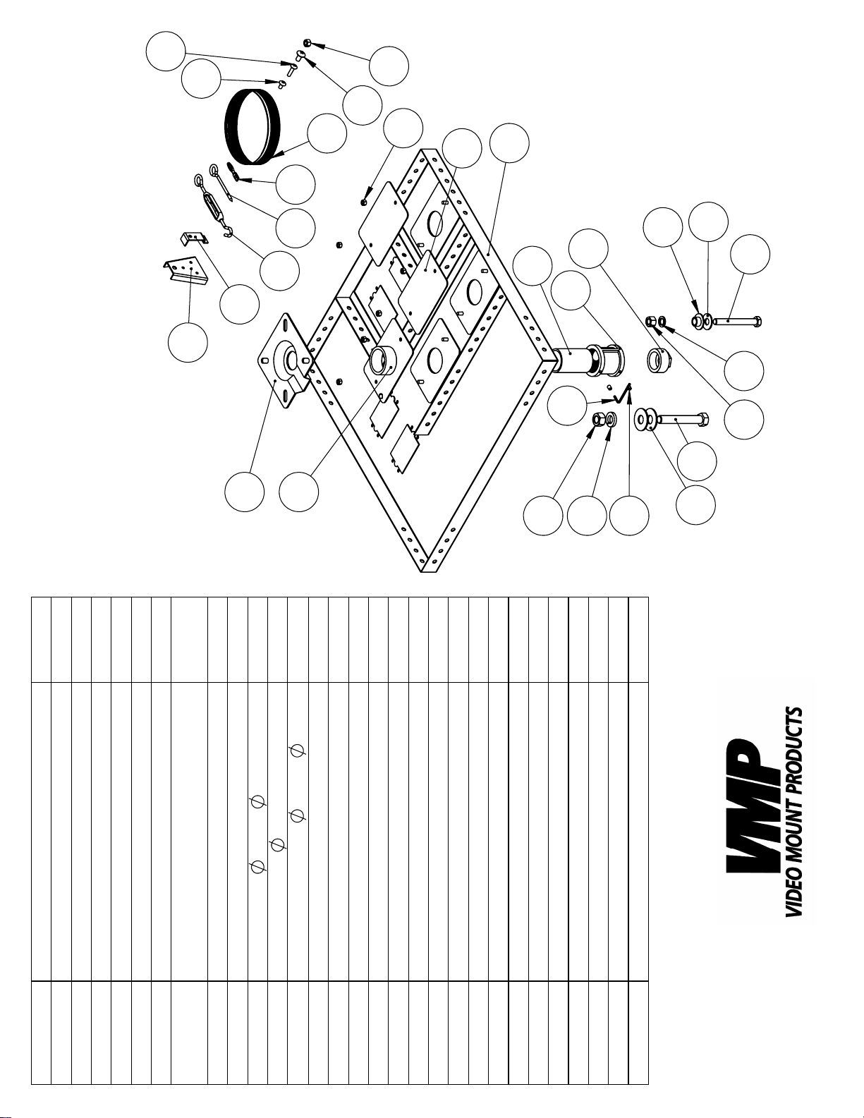
Before starting, lay out all parts to your mount and match them to
the parts list provided. Verify that you have all your parts before
attempting to assemble the mount.
Step 2
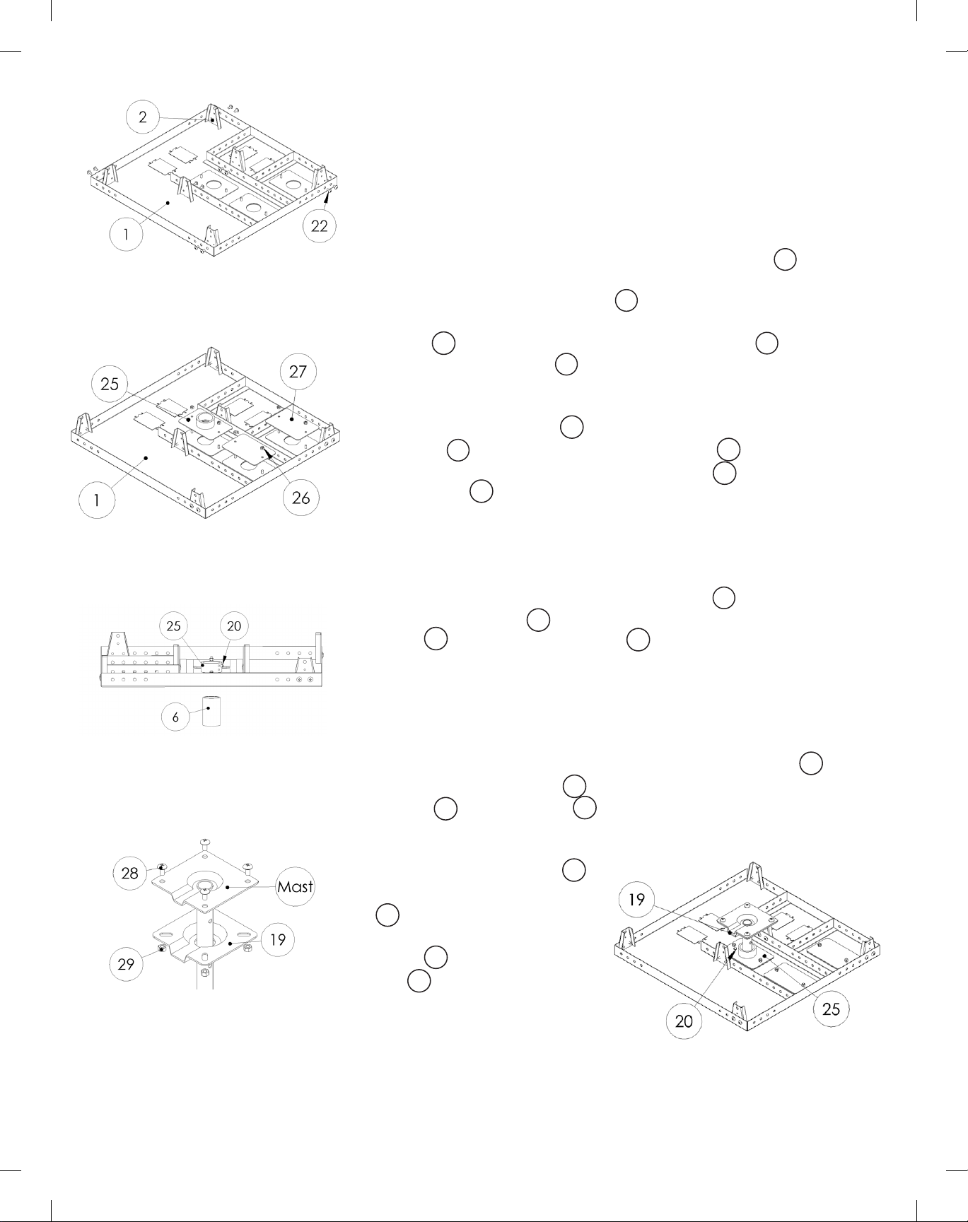
First determine which of the three mounting locations you are going to mount your ceiling mount to the ceiling plate (#1) (center,
1
corner or side). Once you have decided your mounting location
attach two of the side anchors (#2) to the L brackets on the ceil-
2
ing tray at are next to the mounting location using the shorter M6
screws (#22). Attach the remaining side anchors (#2) in the corners of the ceiling plate (#1) towards the inside of the plate.
22
2
1
Step 3
Attach the pipe couple (#25) to the mounting location on the ceiling plate (#1) desired using the M6 hex nuts (#26). Cover the re-
1
maining open holes using the cover plates (#27) and remaining
M6 hex nuts (#26).
26
25
26
27
Step 3: Attaching the pipe couple
to the ceiling plate
Step 4: Threading pipe into the
pipe couple
Step 5: Attaching the adaptor
plate to the ceiling mast
If you are using 1.5” NPT or the near ush pipe:
Step 4
Thread the 1.5” NPT pipe or near ush pipe (#6) into the bottom
of the pipe couple (#25). Secure the pipe by tightening a brake
screw (#20) into the pipe couple (#25) until the brake screw is tight
20
25
25
6
against the threaded pipe. Proceed to step 7.
If you are using a non 1.5” NPT VMP ceiling mast:
Step 5
Nest the top half of the ceiling mast in the adaptor plate (#19). Attach the adaptor plate (#19) and the ceiling mast using the M8
screws (#28) and hex nuts (#29).
28
19
29
19
Step 6
Screw the adaptor plate (#19)
19
into the top of the pipe couple
25
(#25). Secure the adaptor
plate by tightening a brake
screw (#20) into the pipe couple (#25) until the brake screw
20
25
is tight against the adaptor
plate. Follow steps 7 and 8 and
then proceed to step 11.
Step 6: Attaching the adaptor
plate to the pipe couple
Page 4
Step 7: Guide wiring the
ceiling plate
Step 8: Attaching the frame
clamps to the side anchors
Step 7
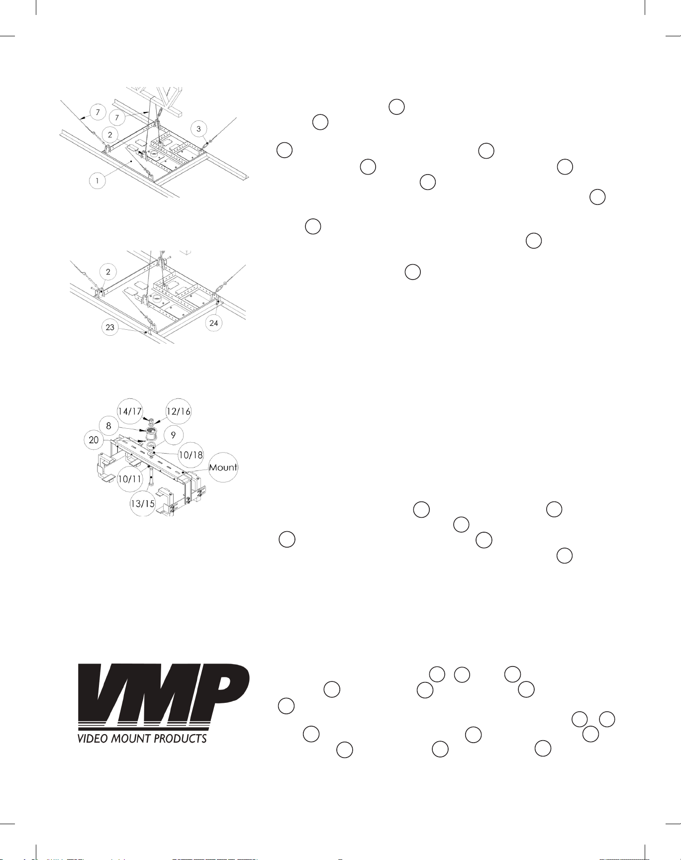
Place the ceiling plate (#1) in the suspended ceiling T-Bars. Using the
tie wire (#7) provided, rst guide wire the two side anchors to a sup-
7
1
port structure above the ceiling. To guide wire, insert a turnbuckle
3
(#3) into the top hole of the side anchor (#2) if using the turnbuckle.
Pass the tie wire (#7) through the eye of the turnbuckle (#3) or the
top hole of the side anchor (#2) and wrap the end of the tie wire
7
2
at least 4 times around itself. Take the other end of the tie wire (#7)
2
3
7
and pass it through an anchor point in the ceiling above the ceiling
plate (#1) again wrapping the free end at least 4 times around itself.
If wooden joists are above your ceiling, eye screws (#5) are included
1
5
to provide anchor points to guide wire to. If anchoring to a concrete
ceiling, concrete anchors (#6) are included to provide anchor points
6
to guide wire to. Metal truss may also provide an anchor point to
guide wire to as well. Make sure the guide wire is supporting the en-
tire weight of the SCM-2, mount and audio/visual equipment. Note:
If mounting to the corner or side you may want to tension the side
anchors higher on the side or corner that the weight is going to be on.
Note: If the distance between the ceiling grid and wherever you’re
attaching the tie wires is longer than 3 feet then you will require more
tie wire (12 gauge steel tie wire). WARNING: Verify whatever support
structure you are anchor your guide wire to can support a minimum
of twice the combined weight of the SCM-2, mount and audio/visual
equipment you are mounting to it. If drilling through a surface verify
that the mounting surface is safe to drill through. If in doubt or uncer-
tain about any of the above, please contact a professional installer.
Step 9: Attaching female pipe
couple to the mount
Step 8
Attach the frame clamps (#24) to the side anchors (#2) located
in the corners of the ceiling plate (#1) using the longer M6 screw
23
(#23). Make sure the frame clamps (#24) are tight against the
24
1
24
T-Bar suspended ceiling frame which the ceiling plate (#1) sits in.
2
1
If you are using 1.5” NPT or the near ush pipe (continued):
Step 9
Determine if the mount you are attaching to requires a 1.5” NPT
adaptor. If it does not then you may skip this step. If you are
mounting to the LCD-2537C, PM-1, PM-2 or PM-3 attach the female pipe couple assembly (#8, #9 and #20) using the large
washers (#10), 5/8” screw (#13), lock washer (#12) and hex nuts
(#14). If you are mounting to the LCD-1C, LCD-1C with LCD-CM2
14
10
13
8
9
or VMP-046/048 attach the female pipe couple assembly (#8, #9
and #20) using the plastic bushing (#18), smaller washer (#11),
M12 screw (#15), lock washer (#16) and hex nuts (#17).
20
15
18
16
20
12
98
11
17
Page 5
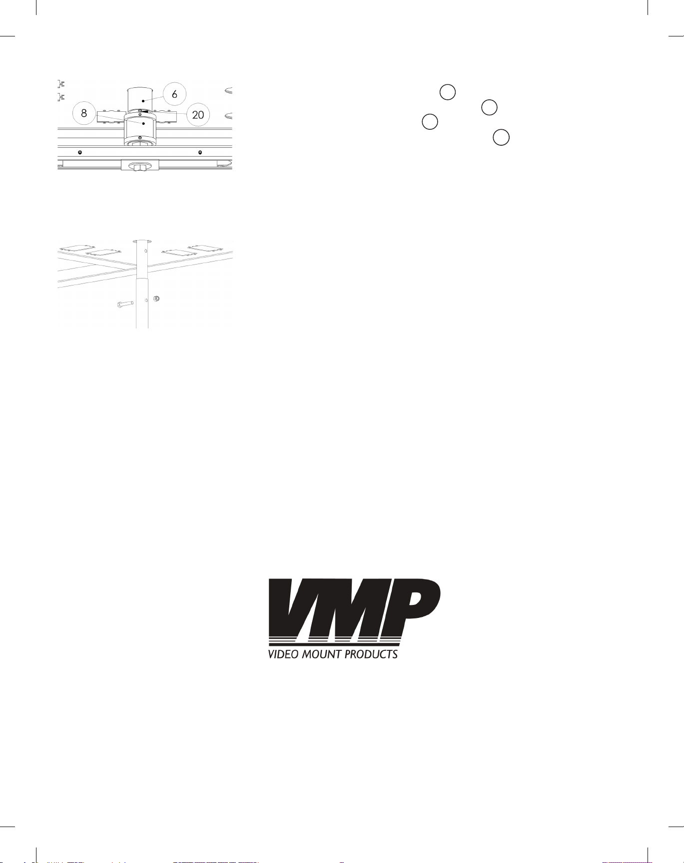
Step 10
Screw the female pipe couple (#8 or the pipe couple provided
with your mount) onto the near ush pipe (#6) or 1.5” NPT pipe. Se-
cure the female pipe couple (#8 or the pipe couple provided with
your mount) by tightening the brake screw (#20 or the brake screw
8
6
8
20
provided with your mount) until the brake screw is tight against the
threaded pipe. Please verify that all nuts and screws are securely
tightened.
Step 10: Securing the female
pipe couple to the pipe
Step 11: Pinning the ceiling
mast together
If you are using a non 1.5” NPT VMP ceiling mast (continued):
Step 11
Attach the mount by through pinning the bottom have of the ceiling
mast to the top half of the ceiling mast using the screw and nylon nut
provided with your mount. Please verify that all nuts and screws are
securely tightened.
Enjoy Your Mount!
WARNING: The installer of these products must verify that the mounting surface, ceiling or wall, will safely
support the combined weight of all attached equipment and hardware. Video Mount Products will not
be held liable for the improper use or installation of its products.
 Loading...