

Page 1
Instruction Sheet For:
PDS-LCM2B
For more information, please contact us at:
345 Log Canoe Circle, Stevensville, Maryland 21666
Toll Free: 877.281.2169 Phone: 410.643.6390 Fax: 410.643.6615
www.videomount.com
Page 2
26
25
23
222120191817161413 15
24
6
27
29
28
2
7
10
11
1
8
4
PDS-LCM2
9
3
5
12
1
2
QTY.
DESCRIPTION
NO.
ITEM
1
Mounting Bracket
Mounting Adaptor
Security Screw M5*P0.8*L20
1
2
3
4
4
6
2
1
2
16*T1.6
5/16"*
Extension Bracket A
4
Nylon Nut M10*P1.5
Washer
Screw 5/16" - 18UNC*L5/8"
6
7
5
2
19*T1.6
3/8"*
Long Allen Key M4
Screw M10*P1.5*L25
Washer
9
8
10
1
1
4
4
4
4
4
4
4
4
Adjusting Bracket
Screw M4*P0.7*L12
Screw M5*P0.8*L12
Screw M6*P1.0*L12
Screw M4*P0.7*L30
Screw M5*P0.8*L30
Screw M6*P1.0*L35
Screw M8*P1.25*L16.5
Adjusting Screw M12*P1.75*L100
11
12
13
14
15
16
17
Screw M8*P1.25*L40
18
19
20
4
4
4
4
Lock Washer M4
Lock Washer M5
Lock Washer M6
21
22
23
4
4
18*T2
5.5*
Spacer M6
Lock Washer M8
Washer
26
24
25
2
4
2
15*T1.0
5*
Spacer M8
Extension Bracket B
Washer
27
28
29
Page 3
WARNING: The installer of these products must verify that the mounting surface, ceiling or
wall, will safely support the combined weight of all attached equipment and hardware.
Video Mount Products will not be held liable for the improper use or installation of its products.
Step 1
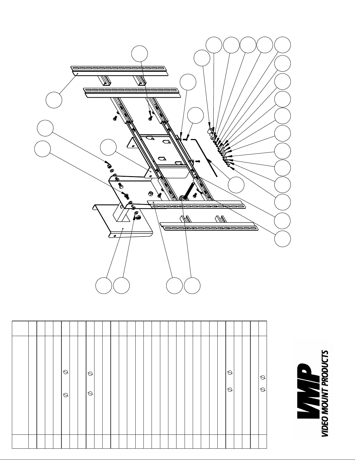
Before starting, lay out all parts to your mount and match them to
the parts list provided. Verify that you have all your parts before
attempting to assemble the mount.
Note: For these instructions PDS-LCB part numbers have hexagons
around their numbers and PDS-LCM2B part numbers have circles
around their part numbers.
Step 2
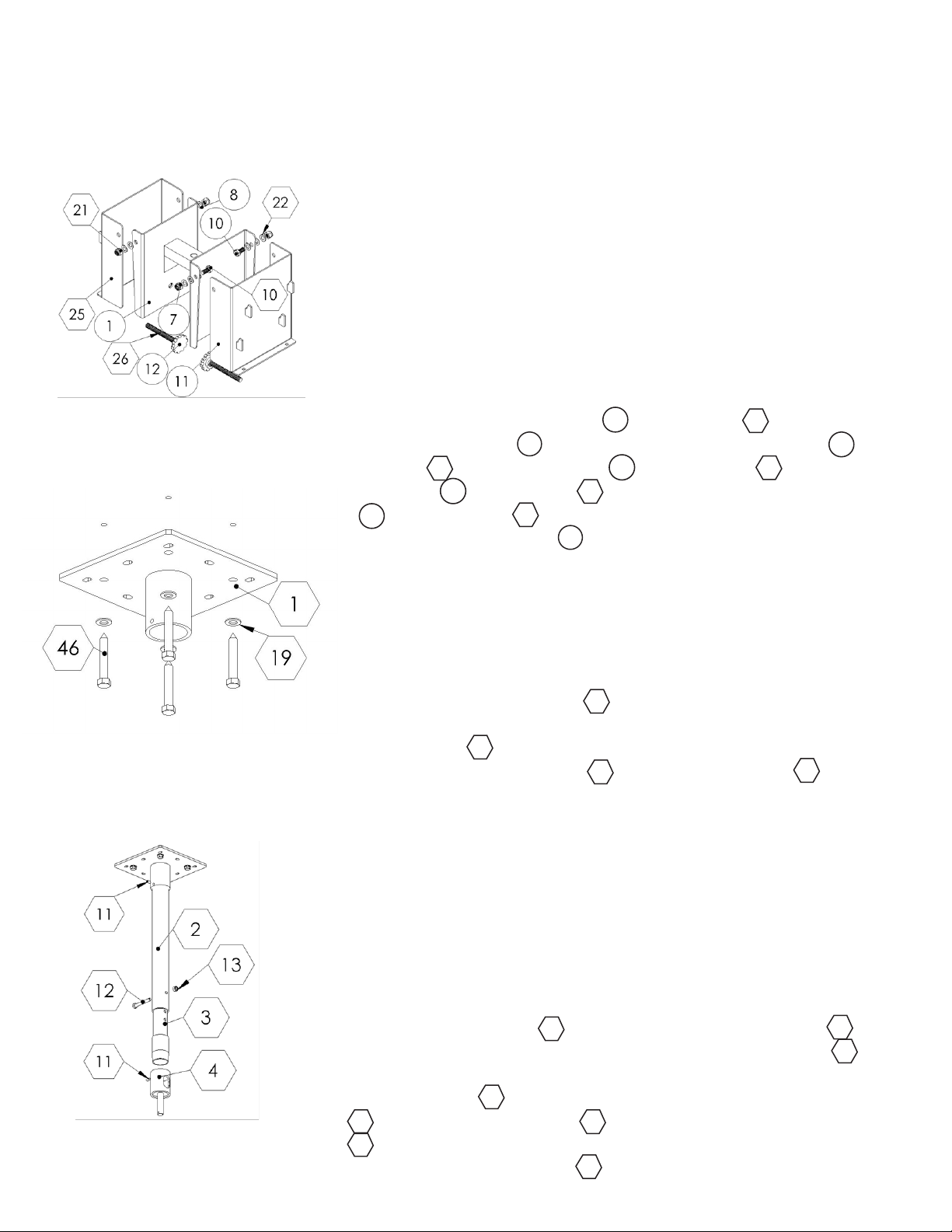
Step 2 : Attaching the adjusting
brackets
Attach the adjusting brackets PDS-LCM2B / PDS-LCB to the
mounting adaptor PDS-LCM2B using the M10 screws PDSLCM2B / PDS-LCB, washers PDS-LCM2B / PDS-LCB and
nylon nuts PDS-LCM2B / PDS-LCB. Insert the adjusting screw
12
PDS-LCM2B / PDS-LCB into the welded nuts located in
10
7
1
26
the mounting adaptor PDS-LCM2B Note: You will have to
11
8
21
1
thread the rst adjusting screw all the way down to provide space
to thread in the second screw. Once the second screw is started
you can back off the rst to the desired tilt angle.
25
10
22
Step 3: Attaching the ceiling
plate to the ceiling
Step 4 : Attaching the ceiling
mast to the ceiling plate
Step 3
Mark the ceiling or desired mounting surface in preparation of
installation of ceiling plate PDS-LCB. If mounting to wooden
1
ceiling joists, pre drill pilot holes using a 7/32” drill bit. Attach the
ceiling plate PDS-LCB to the wooden ceiling joist using the
5/16” by 2.5” long lag screw PDS-LCB and washer PDS-LCB.
1
46
19
WARNING: Please verify that your mounting surface will support
the combined weight of your mount, mounting hardware, and at
panel. Also verify that the mounting surface is safe to drill through.
Please note only mounting hardware for mounting to wooden ceiling joists will be provided with the unit. If mounting to a surface
other than wooden ceiling joists then other hardware will be required. If in doubt or uncertain about any of the above, please
contact a professional installer.
Step 4
Screw the outer mast PDS-LCB into the ceiling plate PDS-
2
LCB. Secure the outer mast by tightening the brake screw PDS-
1
11
LCB into the thread hole in the side of the ceiling plate. Attach
the inner mast PDS-LCB to the outer mast using the M8 screw
2 PDS-LCB and nylon nut PDS-LCB. Attach the pipe couple
PDS-LCB to the bottom of the inner mast and secure the pipe
4
couple with a brake screw PDS-LCB.
3
1312
11
Page 4
Step 5 : Attaching the mounting
adaptor to the pipe couple
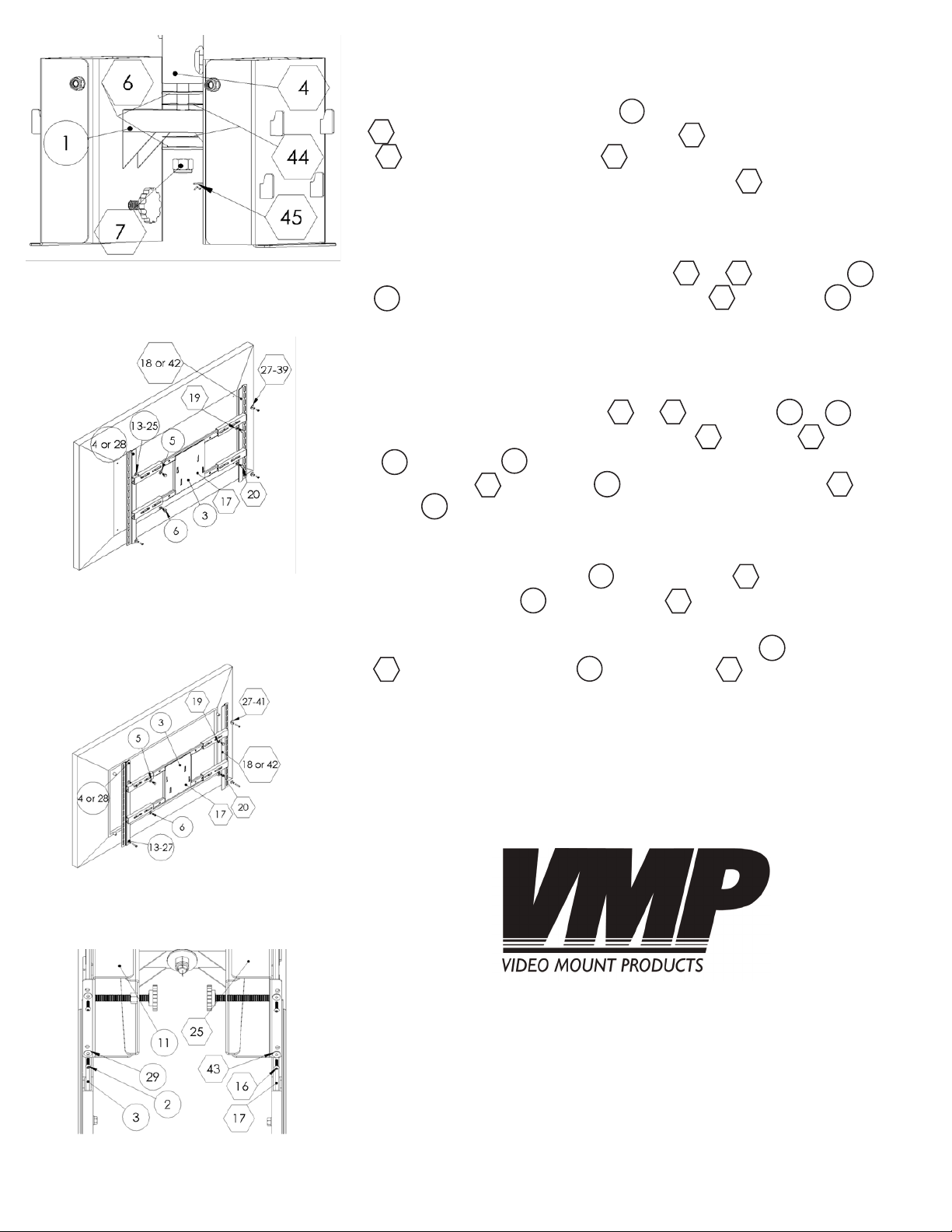
Step 5
Attach the mounting adaptor PDS-LCM2B to the pipe couple
4
PDS-LCB using the metal washers PDS-LCB, PVC washers
44
PDS-LCB and nylon nut PDS-LCB. After tightening down
the nylon nut completely insert the cotter pin PDS-LCB though
1
6
7
45
the hole in the bottom of the screw of the pipe couple.
Step 6
Slide either extension brackets A or B or PDS-LCB / or
28
PDS-LCM2B onto the mounting plate PDS-LCB / PDS-
18 42
17
4
3
LCM2B and match up the slots on the extension brackets to the
holes on the back of your TV. Determine the correct screw size
and if you need to use washers, lock washers, or spacers. Note:
Spacers are used for TVs with recessed hole patterns. Secure the
4
TV to the extension brackets or PDS-LCB / or PDSLCM2B using the appropriate hardware through PDS-LC/
through PDS-LCM2B. Secure extension brackets with
13
5/16” screw PDS-LCB / PDS-LCM2B and washer PDSLCB / PDS-LCM2B.
5
27
20
18 42
27 41
6
28
19
Step 6A: Attaching the mounting rails
to the at panel
(holes are not recessed)
Step 6B: Attaching the mounting rails
to the at panel (holes are recessed)
Step 7
Lift the mounting bracket PDS-LCM2B / PDS-LC onto the
adjusting bracket PDS-LCM2B / PDS-LCB. WARNING: This
11
3
25
17
step requires at least two people to prevent possible injury. Secure
the plates together using the M5 security screw PDS-LCM2B /
16
PDS-LCB and washer PDS-LCM2B / PDS-LCB.
29
2
43
Please verify that all nuts and screws are securely tightened.
Step 7: Attaching the mounting
brackets to the adjusting brackets
Enjoy Your Mount!
WARNING: The installer of these products must verify that the
mount surface, ceiling or wall, will safely support the combined
weight of all attached equipment and hardware. Video Mount
Products will not be held liable for the improper use or installation
of its products.
 Loading...