

Page 1
VIDEO MOUNT PRODUCTS
Instruction Sheet For:
LCD-WM2
For more information, please contact us at:
325 Log Canoe Circle, Stevensville, Maryland 21666
(T) 410.643.6390 / (F) 410.643.6615
www.videomount.com
Page 2
Step 2: Attaching the wall
plate to the wall
(Lag screws are not included)
Step1
Before starting, lay out all parts to your mount and match them to the
parts list provided. Verify that you have all your parts before attempting to assemble the mount. Note: The LCD-WM2 and LCD-1 combo was
designed to mount two of the same TV or TVs of similar size and weight.
It is not designed to have two signifi cantly different TVs mounted. Also
note that LCD-1 part numbers have circles around their numbers and
LCD-WM2 has hexagons around its part numbers.
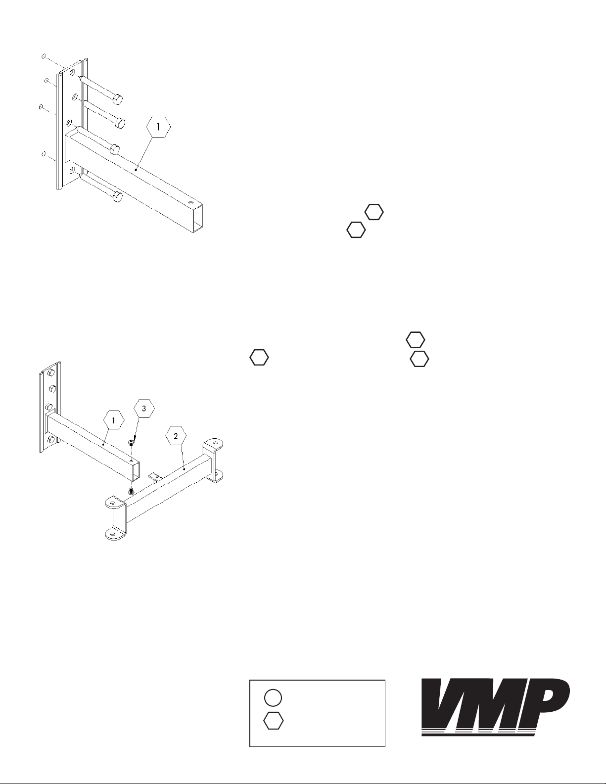
Step 2
Mark the wall or desired mounting surface in preparation of installation of the wall plate LCD-WM2. Pre-drill, if necessary, and
mount the wall plate LCD-WM2 to the desired mounting surface.
Warning: Please verify that your mounting surface will support the
combined weight of your mount, mounting hardware, and monitor. Also verify that the mounting surface is safe to drill through. If in
doubt, please contact a professional installer.
1
1
Step 3
Attach the connector support LCD-WM2 to the wall plate
1
LCD-WM2 using the M6 screws LCD-WM2.
2
3
Step 3: Attaching the connector
support to the wall plate
Key:
LCD-1
LCD-WM2
VIDEO MOUNT PRODUCTS
Page 3

Step 4: Attaching the LCD-1s to the
connector support
Step 4
For this step it is assumed that the LCD-1s are assumed in the
specifi c confi guration (near fl ush, single arm, or double arm) de-
sired with the pivot bracket LCD-1 and mounting plate or
LCD-1 attached. If not please take the time to do so now. In-
6
sert the plastic fl anges LCD-1 into the desired force arms or
LCD-1. Attach the desired force arms or LCD-1 to the
8
connector support LCD-WM2 using the 3/8” screw LCD-1
and nylon nut LCD-1.
2
11
4 5
18
2
2
8
17
Step 5
Attach the TVs to the mounting plates or LCD-1 using the M4
19
LCD-1 or M5 LCD-1 screws as appropriate. Please verify
that all nuts and screws are tight.
20
5
6
Step 5: Attaching the TVs to
the LCD-1s
VIDEO MOUNT PRODUCTS
Enjoy Your Mount!
WARNING: The installer of these products must verify that the mounting surface, ceiling or wall, will safely support the combined weight
of all attached equipment and hardware. Video Mount roducts will
not be held liable for the improper use or installation of its products.
 Loading...