

Page 1
VIDEO MOUNT PRODUCTS
For more information, please contact us at:
345 Log Canoe Circle, Stevensville, Maryland 21666
Toll Free: 877.281.2169 Phone: 410.643.6390 Fax: 410.643.6615
www.videomount.com
LCD-MID-CM2 & LCD-MID-CM2B
Instruction Sheet For:
Page 2
12
9
8
5
1
2
7
6
13
1
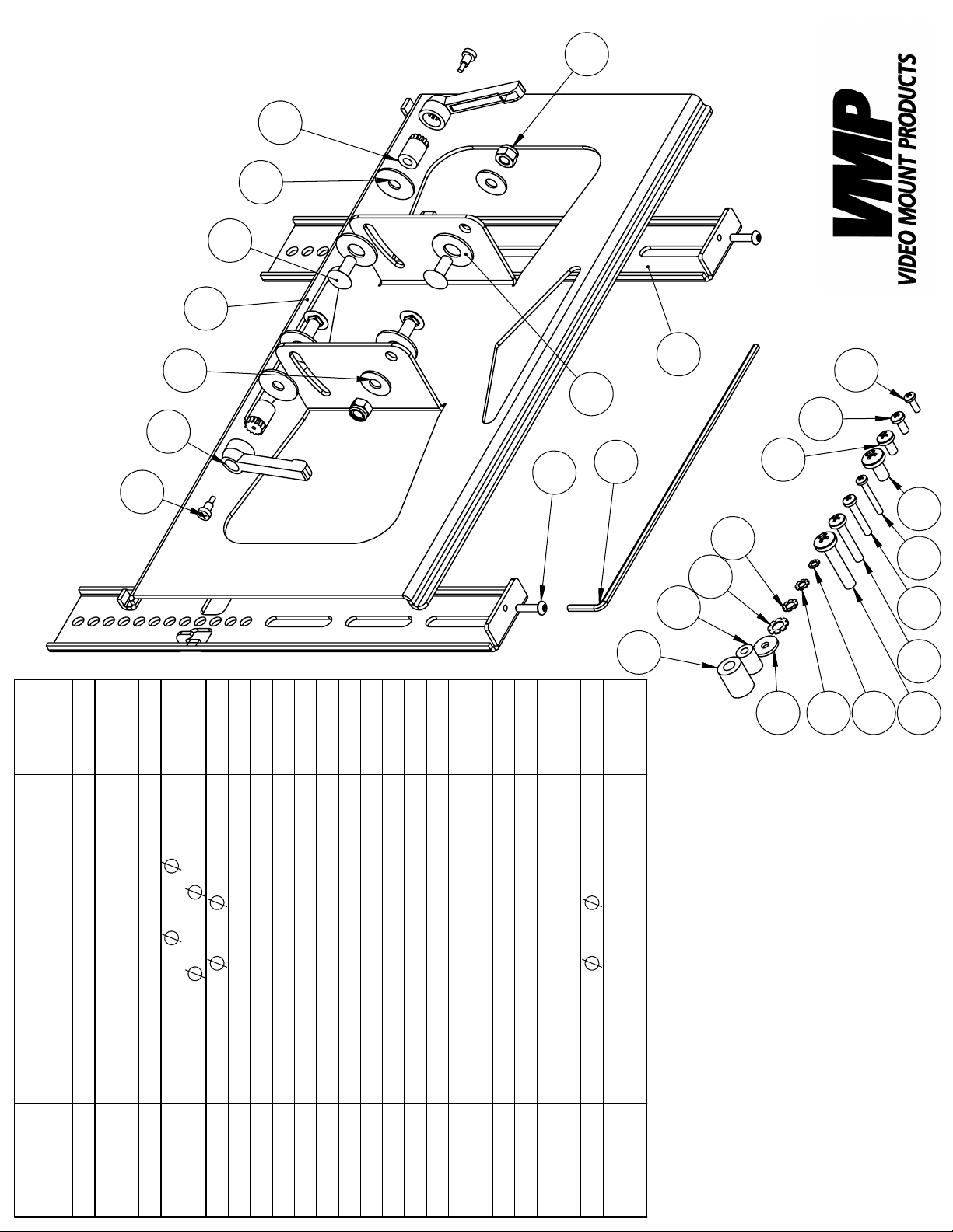
QTY.
10
3
11
LCD-MID-CM2
2
2
2
1
4
4
30*T1.8
19*T1.6
25*T2.0
2
2
2
2
2
4
4
4
4
4
4
4
4
4
4
4
4
4
18*T2.0
14
4
23
24
26
27
4
4
15
25
22
1617181920
21
Tilt Plate
DESCRIPTION
Long Allen Key M4
Screen Mounting Brackets
Security Screw M5*P0.8*L20
Carriage Screw M8*P1.25*L20
1
2
3
4
5
ITEM NO.
12.5*
8.5*
5/16"*
Gear Nut
Lever Screw
Lever Handle
Washer
Washer
Nylon Washer
9
8
7
6
10
11
Screw M4*P0.7*L12
Screw M5*P0.8*L12
Screw M6*P1.0*L12
Screw M4*P0.7*L30
Screw M5*P0.8*L30
Nylon Nut M8*P1.25
12
13
Screw M8*P1.25*L16
14
15
16
Screw M6*P1.0*L35
Screw M8*P1.25*L40
17
18
19
20
5.5*
Spacer M6
Spacer M8
Lock Washer M4
Lock Washer M5
Lock Washer M6
Lock Washer M8
Washer
26
21
22
23
24
25
27
Page 3

Step 2: Attaching the tilt plate
Step 1
Before starting, lay out all parts to your mount and match them to the
parts list provided. Verify that you have all your parts before attempting to assemble the mount. Note: For the purposes of these instruc-
tions it is assumed you have assembled and mounted the LCD-MIDC. If you have not done so, then proceed to do so at this time. Note:
For these instructions LCD-MID-C parts are labeled with hexagons and
LCD-MID-CM2 parts are labeled with circles.
Step 2
10
1
6
12
1
10
9
11
7
7
7
Attach the tilt plate LCD-MID-CM2 to the base plate LCD-MID-C
by fi rst inserting plastic washers LCD-MID-CM2 in between the base
plate and tilt plate on each side. Then insert the 5/16” by ¾” long square
neck screws LCD-MID-CM2 into the base plate LCD-MID-C so
the screws are pointed outwards. On the bottom screws on each side
secure the screws with the 19 mm outer diameter washers LCD-MID-
CM2 and nylon nuts LCD-MID-CM2. On the upper screws place
the 25 mm outer diameter washers LCD-MID-CM2 and use the gear
1
nuts LCD-MID-CM2, lever handle LCD-MID-CM2 and lever screw
LCD-MID-CM2 to secure the tilt plate’s LCD-MID-CM2 position.
8
Tilt the tilt plate LCD-MID-CM2 as far up as it will go and lock the tilt
into place by tightening down the lever handle LCD-MID-CM2 as
far as it will go on each side. Note: This is important to do to allow step
4 to be accomplished safely and easily.
5
Step 3: Attaching the mounting brack-
ets to the screen (spacers not needed)
Step 3: Attaching the mounting
brackets to the screen (spacers used
due to recessed hole patterns)
Step 3
Determine the correct screw size and if you need to use washers, lock
washers, or spacers. Note: Spacers are used for TVs with recessed hole
patterns. Secure the display to the screen mounting brackets LCDMID-CM2 using the appropriate hardware (LCD-MID-CM2 through
).
Note: The brackets have to be level with each other to work properly.
27
2
13
Step 4
Make sure the tilt plate LCD-MID-CM2 is locked into place by
tightening down the lever handles LCD-MID-CM2 as far as they
will go. Lift the screen mounting brackets LCD-MID-CM2 with the
attached fl at panel onto the tilt plate LCD-MID-CM2. Then while
another person is holding the fl at screen in place tighten down the
security screws LCD-MID-CM2 as far as they will go with the long
Allen key LCD-MID-CM2 to lock the screen mounting brackets
LCD-MID-CM2 into place. Once the screen mounting brackets
2
LCD-MID-CM2 are secure then you can adjust the tilt by loosen-
2
ing the lever handles LCD-MID-CM2 and adjusting the tilt plate
LCD-MID-CM2 to the desired position and then retightening the
1
lever handles LCD-MID-CM2 once it is in position. Please verify
that all nuts and screws are securely tightened.
3
4
10
1
10
2
1
10
Step 4: Attaching the mounting
brackets to the tilt plate
Enjoy Your Mount!
WARNING: The installer of these products must verify that the mount
surface, ceiling or wall, will safely support the combined weight of all
attached equipment and hardware. Video Mount Products will not
be held liable for the improper use or installation of its products.
 Loading...