

Page 1

Instruction Sheet For:
LCD-CM2B
For more information, please contact us at:
345 Log Canoe Circle, Stevensville, Maryland 21666
Toll Free: 877.281.2169 Phone: 410.643.6390 Fax: 410.643.6615
www.videomount.com
Page 2

11
1
8
12
13
10
65
LCD-CM2B
1
1
1
1
1
QTY.
DESCRIPTION
Pivot Bracket
Support Tube
Nylon Nut M6*P1.0
Small Mounting Plate
Nylon Nut 3/8"-18UNC
9
1
1
Adjustable Screw 1/4"-
Hex Screw M6*P1.0*L35
2
2
2
19*T1.6
10.2*
20UNC*L2"
Cable Clip
Washer
7
1
4
Cross Screw M4*P0.7*L12
Hex Screw 3/8"-18UNC*L2"
3
4
Cross Screw M5*P0.8*L12
NO.
ITEM
1
2
3
5
6
7
8
9
11
12
10
13
Page 3
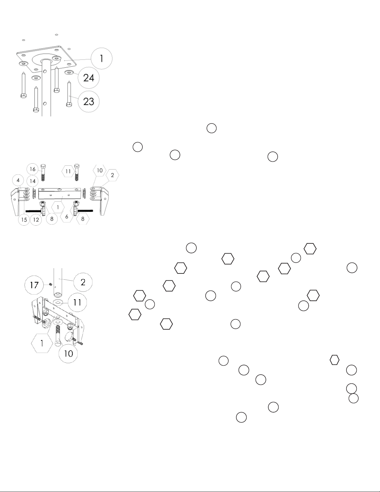
Step 2: Mounting the ceiling plate
Step 1
Before starting, lay out all parts to your mount and match them to
the parts list provided. Verify that you have all your parts before attempting to assemble the mount. Note: The LCD-CM2B and LCD-1CB
combo was designed to mount two of the same TV or TVs of similar
size and weight. It is not designed to have two signifi cantly different
TVs mounted. Note: LCD-1CB part numbers have circles around their
numbers and LCD-CM2B has hexagons around their part numbers.
Step 2
Mark the ceiling or desired mounting surface in preparation of installation of ceiling plate (
#1 LCD-1CB). If mounting to wooden ceiling
1
joists, pre drill pilot holes using a 7/32” drill bit. Attach the ceiling plate
(
LCD-1CB) to the wooden ceiling joist using the 5/16” by 2.5” long
1
lag screw (
23
#23 LCD-1CB) and washer ( LCD-1CB). WARNING:
24
Please verify that your mounting surface will support the combined
weight of your mount, mounting hardware, and fl at panel. Also ver-
ify that the mounting surface is safe to drill through. Please note only
mounting hardware for mounting to wooden ceiling joists will be provided with the unit. If mounting to a surface other than wooden ceiling joists then other hardware will be required. If in doubt or uncertain
about any of the above, please contact a professional installer.
Step 3: Attaching the pivot
bracket to the support tube
Step 4: Attaching the extension
tube to the support tube
Step 3
Insert end plugs (
Attach the pivot brackets (
support tube (
LCD-1CB) between the support tube (#1 LCD-CM2B) and the pivot
brackets (
11
(
#11 LCD-CM2B and #16 LCD-1CB) and nylon nut (#6 LCD-CM2B
and
8
#8 LCD-1CB). Thread the adjusting screws (#12 LCD-1CB and
#8 LCD-CM2B) into the threaded hole in the bottom of the pivot
8
brackets
2
#2 LCD-CM2B and #4 LCD-1CB) and two inch hex screw
(#2 LCD-CM2B and #4 LCD-1CB) until the bottom of the
2
14
#14 LCD-1CB) into the support tube (# 1 LCD-CM2B).
#2 LCD-CM2B and #4 LCD-1CB) to the
2
# 1 LCD-CM2B) using washers (#1 0 LCD-CM2B and #15
1
1
4
16
4
10
1
4
15
6
12
screw is roughly even with the front of the pivot bracket.
Step 4
Attach the extension tube (
CM2B) using the large washers
LCD-1CB). Make sure the M12 screw (#10 LCD-1CB) is tight and once
2
#2 LCD-1CB) to the support tube (#1 LCD-
11 10
(#11 LCD-1CB) and M12 Screw (#10
10
it is tight secure the screw in place by tightening the brake screw (
LCD-1CB) in the threaded hole in the side of the extension tube (
LCD-1CB). Make sure the brake screw (
possible against the M12 screw (
#10 LCD-1CB) to properly secure that
10
17
#17 LCD-1CB) is as tight as
1
17
#17
2
#2
screw.
Page 4
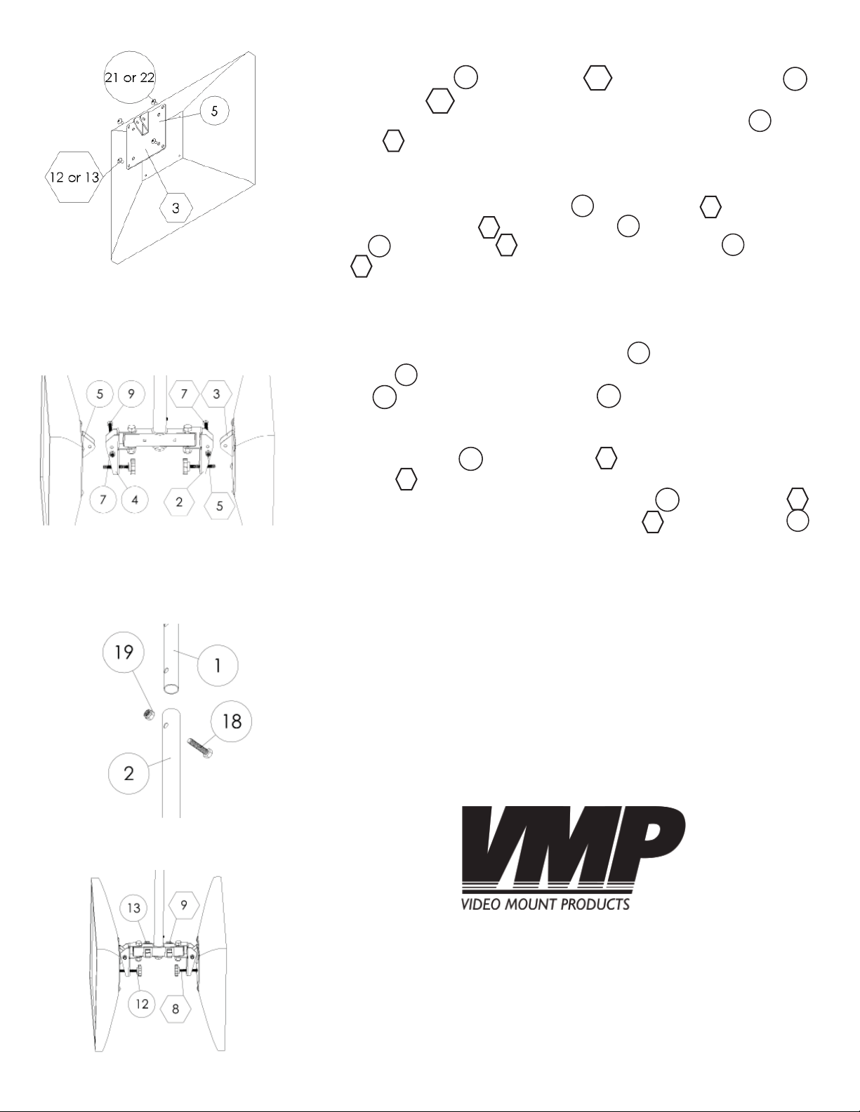
Step 5
Use either the M4 (#22 LCD-1CB and #12 LCD-CM2B) or the M5 (#21
LCD-1CB and #13 LCD-CM2B) screws as appropriate for your fl at
22
13
panels to attach your fl at panels to the mounting plates (
1CB and
3
#3 LCD-CM2B).
12
21
5
#5 LCD-
Step 6
Through bolt the mounting plates (#5 LCD-1CB and #3 LCD-CM2B)
to the pivot brackets (
screw (
and
9
#9 LCD-1CB and #7 LCD-CM2B) and nylon nut (#7 LCD-1CB
5
#5 LCD-CM2B).
#2 LCD-CM2B and #4 LCD-1CB) using the M6
2
7
5
4
3
7
Step 5: Attaching the fl at panel to
the mounting plate
Step 6: Attaching the mounting
bracket to the pivot bracket
Step 7
Determine the height at which you want to mount the fl at pan-
els and through bolt the extension tube (
ing plate (
screw (
#1 LCD-1CB) at the appropriate height using the 5/16”
1
#18 LCD-1CB) and nylon nut (#19 LCD-1CB).
18
2
#2 LCD-1CB) to the ceil-
19
Step 8
Insert cable clips (
port tube (
1
#1 LCD-CM2B) for cable management. To adjust the tilt
13
#13 LCD-1CB and #9 LCD-CM2B) into the sup-
of the fl at panels thread the adjusting screw (
LCD-CM2B) further into the pivot bracket (#2 LCD-CM2B and #4
9
12
#12 LCD-1CB and #8
2
8
4
LCD-1CB) to increase the tilt up and back to adjust the tilt down.
Please verify that all nuts and screws are securely tightened.
Step 7: Attaching the extension tube
to the ceiling plate
Step 8: Final adjustments
Enjoy Your Mount!
WARNING: The installer of these products must verify that the mount surface, ceiling or wall, will safely support the combined weight of all attached equipment and hardware. Video Mount Products will not be held
liable for the improper use or installation of its products.
 Loading...