

Page 1
Instruction Sheet For:
IBA-1
For more information, please contact us at:
345 Log Canoe Circle, Stevensville, Maryland 21666
Toll Free: 877.281.2169 Phone: 410.643.6390 Fax: 410.643.6615
www.videomount.com
Page 2
1
1
1
QTY.
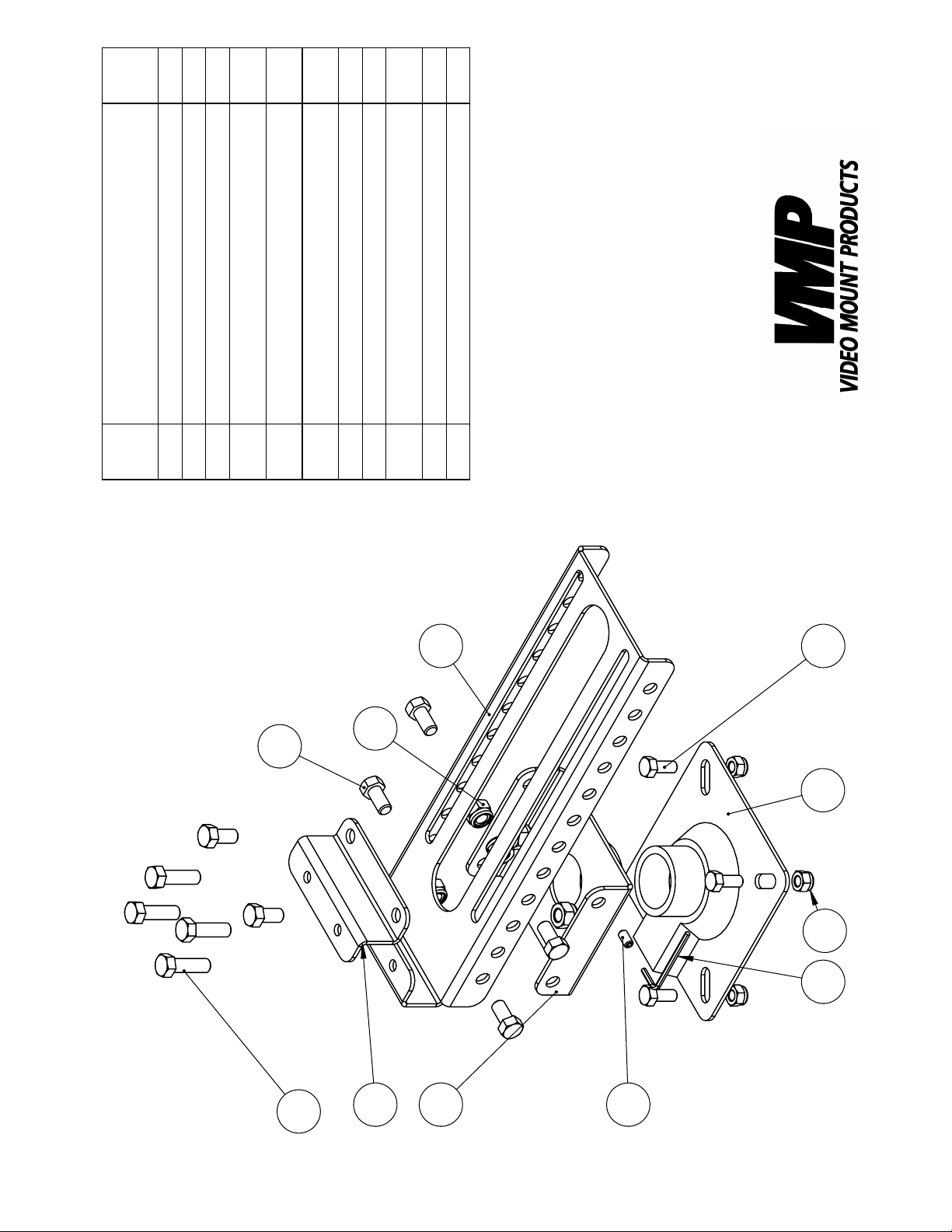
Main Plate
Slider Plate
DESCRIPTION
Pipe Couple
4
4
6
16UNC*L3/4"
16UNC*L1.25"
6
18UNC*L3/4"
4
1
1
1
M3 Allen Key
Adaptor Plate
Hex Head Screw 3/8" -
Hex Head Screw 3/8" -
3
NO.
ITEM
1
2
4
IBA-1
Nylon Nut 3/8"-16UNC
Hex Head Screw 5/16" -
6
5
4
Nylon Nut 5/16" - 18UNC
Brake Screw 1/4" - 20UNC*L1/2"
7
8
9
10
11
1
7
6
10
8
11
5
2
3
9
Page 3
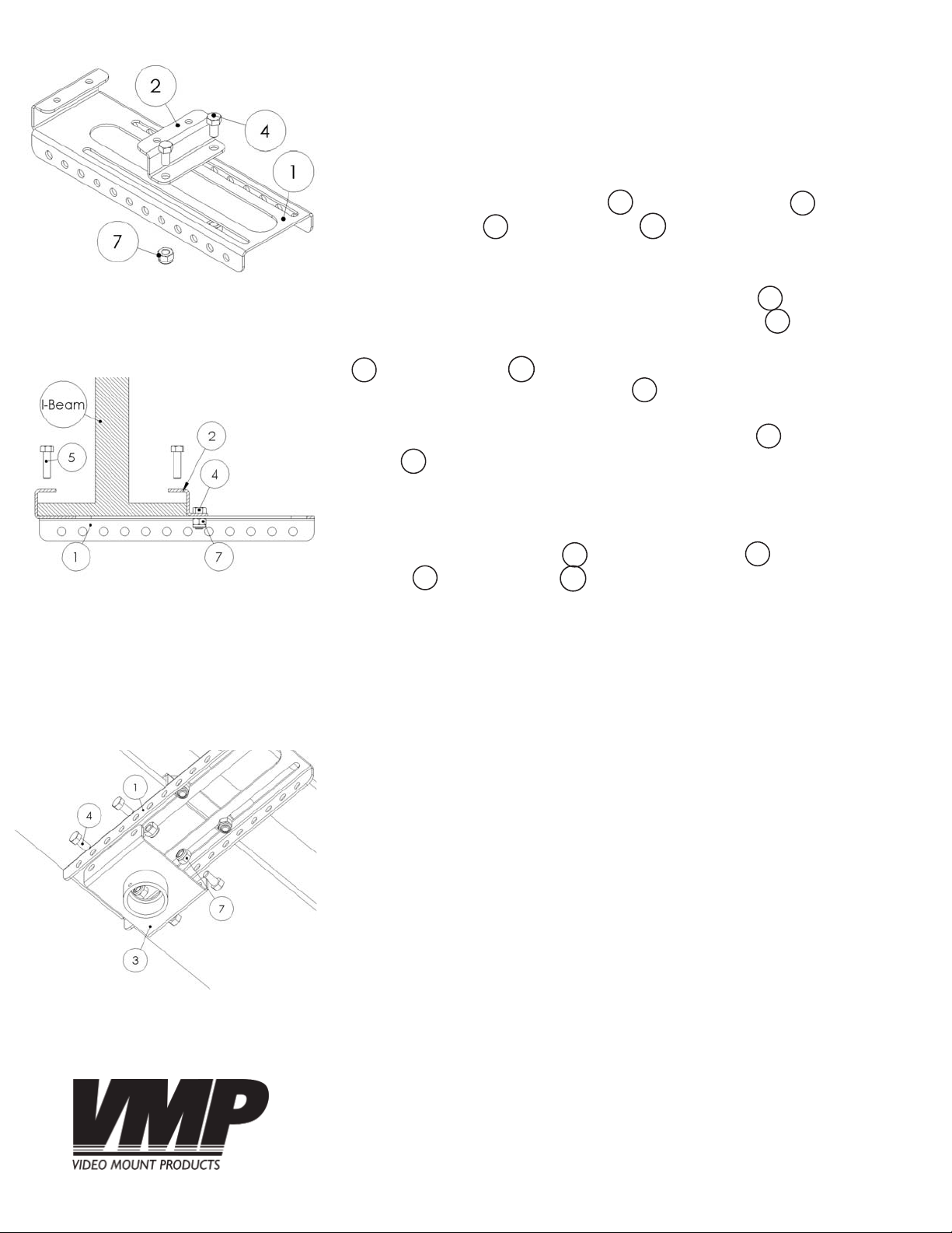
Step 2: Attaching the slider
plate
Step 1
Before starting, lay out all parts to your mount and match them to
the parts list provided. Verify that you have all your parts before
attempting to assemble the mount.
Step 2
Loosely attach the slider plate to the main plate using the
3/8” hex screws and nylon nuts .
4
2
7
1
Step 3
Place the underside upper lip of the main plate tight against
one of the I-Beam fl anges and slide the slider plate tight against
1
2
the other side of the I-Beam fl ange. Tighten the 3/8” screws
and nylon nuts on the slider plate to prevent further move-
4
ment. Use the longer 3/8” screw to secure the I-Beam fl ange
7
5
against the main plate by tightening them down through the
threaded holes in the upper lip of the main plate and the slider
plate . Please verify all screws and nuts are completely and
2
1
securely fastened at this point.
Step 3:Attaching the main
plate to the I-Beam
Step 4
Attach the pipe couple to the main plate using the 3/8”
screws and nylon nuts .
4
3
7
1
Step 4: Attach the pipe couple
Page 4
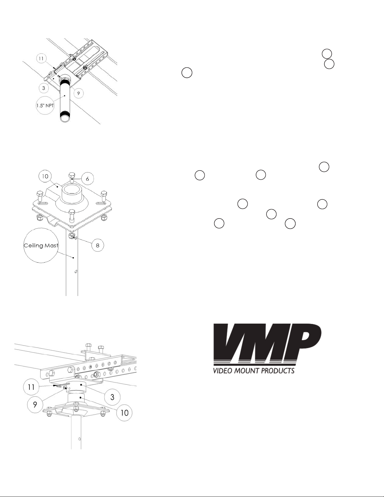
If you are using 1.5” NPT pipe:
Step 5
Screw the pipe into the bottom of the pipe couple . Secure
the pipe from turning by screwing in the brake screw with the
allen key as tight as possible.
11
3
9
WARNING: To prevent possible injury that could occur if the 1.5”
NPT pipe turns out of the Pipe Couple, please verify that you
have tightened the brake screw as far as possible.
Step 5: Attaching 1.5” NPT pipe
Step 6: Attaching the ceiling
mast to the adaptor plate
If you are using a VMP ceiling mast:
Step 6
Attach the VMP ceiling mast to the adaptor plate using the
5/16” screws and nylon nuts .
6
8
10
Step 7
Thread the adaptor plate into the pipe couple as tight as
possible. Secure the adaptor plate from turning by threading
in the brake screw with the allen key as tight as possible.
9
10
10
11
3
WARNING: To prevent possible injury that could occur if the
adaptor plate of the pipe couple, please verify that you have
tightened the brake screw as far as possible.
Step 7: Attaching the
adaptor plate to the pipe
couple
Enjoy Your Mount!
WARNING: The installer of these products must verify that
the mounting surface, ceiling or wall, will safely support the
combined weight of all attached equipment and hardware.
Video Mount Products will not be held liable for the improper
use or installation of its products.
 Loading...